

Page 1
Data Sheet
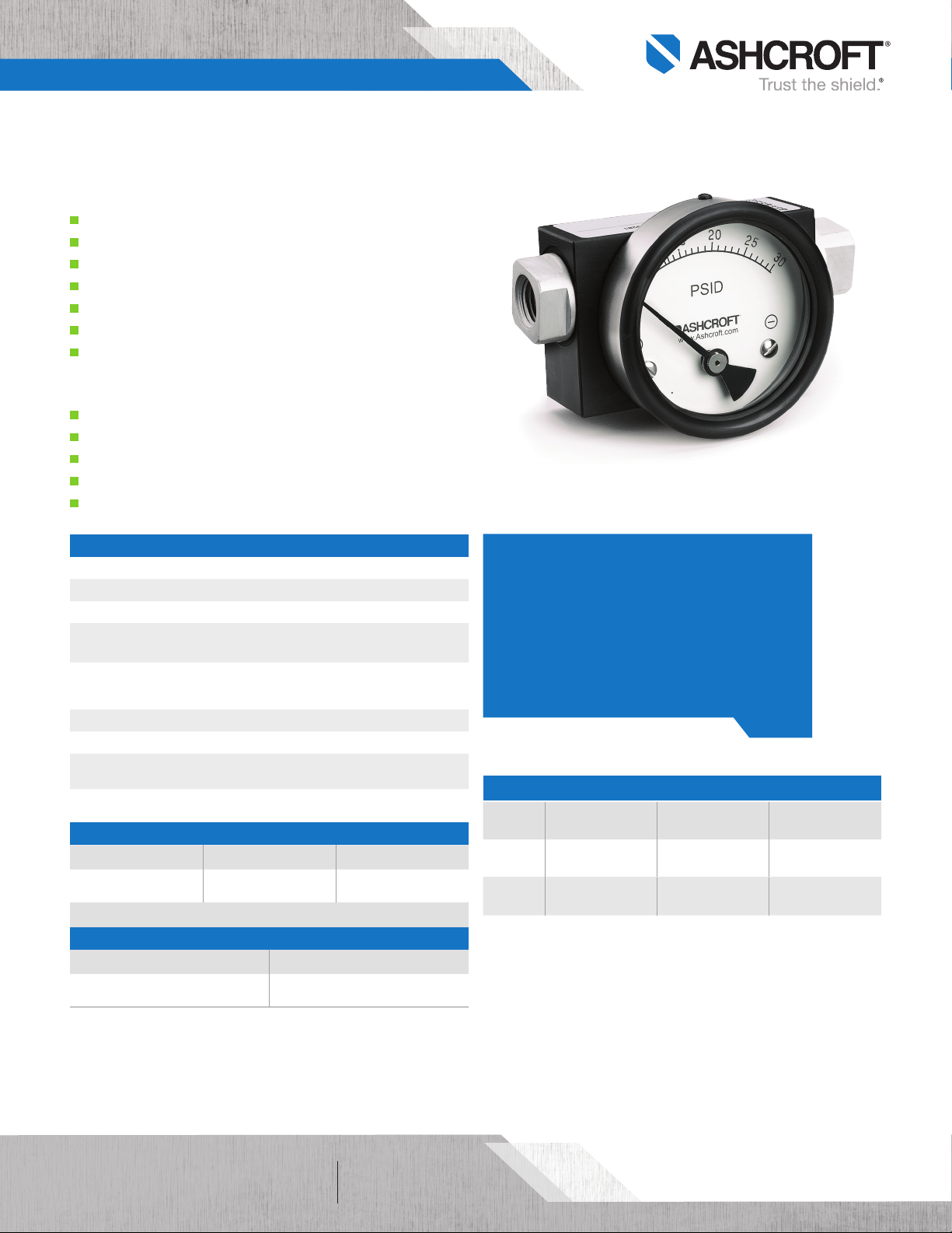
1130 Differential Pressure Gauge
FEATURES
High static pressure capabilty (up to 6,000 psi)
Ranges from 5 psi to 150 psi
Reed switches optional for direct system control
Superior magnets for smoother pointer motion
Buna-N O-rings (others available)
Piston actuator
Dry or liquid filled case
TYPICAL USES
Filtration monitoring
Hydraulics
Flow rate
Pump performance
Measuring Pressure Drop
1130
2˝, 2½˝, 3½˝, 4˝, 4½˝, 6˝ dial sizes
SPECIFICATIONS
Accuracy: ±2% ascending pressure full scale differential
Sizes: 2˝, 2 ½˝, 3 ½˝, 4˝, 4 ½˝, 6˝
Ranges: 0-5 psi to 150 psi
Process Connection
Location:
Process Connection
Size:
Migration: Minor migration of process media
Weather Protection: IP65
Maximum Process
Temperature:
Maximum Static
Pressure:
WETTED COMPONENTS
Actuator O-Rings/Diaphragm Body Material
Piston Buna-N
Ceramic magnet & SS spring are also wetted components
NON-WETTED COMPONENTS
Case Material Window
Stainless steel
Lower, back, in-line
¼ NPT Female (STD.), 1⁄8 NPT or ½ NPT Female
Adapters (OPT.)
175°F (80°C)
3,000 psi (6,000 psi for Stainless steel)
Aluminum, brass or
stainless steel
Glass (STD.), safety glass or plastic
(OPT.)
KEY BENEFITS
• Recommended for high differential and high
static pressure
• Low Cost
• Stainless steel Case
• Switch outputs available
• 5 year warranty
RATINGS FOR STANDARD REED SWITCHES
Switches Contact Rating Current Voltage
SPST
SPDT
10 VA ac (rms) or
dc (Max.)
3 VA ac (rms) or
dc (Max.)
0.5 Amp ac (rms) or
dc (Max.)
0.3 AMP ac (rms) or
dc (Max.)
100 Vac/Vdc
(Max.)
30 Vac/Vdc
(Max.)
All specifications are subject to change without notice.
All sales subject to standard terms and conditions.
©2018 Ashcroft Inc. 1130_gauge_ds_RevB_Ltr_07-29-19
of 31
ashcroft.com
info@ashcroft.com
1.800.328.8258
Page 2
Data Sheet
1130 Differential Pressure Gauge
ORDERING CODE Example:
Size
20 - 2˝ 20
25 - 2½˝
35 - 3½˝
40 - 4˝
45 - 4½˝
60 - 6˝
Series
1130 - Piston Actuated 113 0
Body Material
A - Brass A
F - Aluminum
S - Stainless steel
Case Fill
D - Dry D
L - Glycerin fill (Liquid fill has an effect on accuracy that varies with range and temperature.)
Process Connection Size
25 - ¼ NPT Female 25
Process Connection Location
S - In-Line S
L - Lower
B - Back
Options (If choosing an option(s) must include an “X”) X__
BF - Surface mounting plate
CS - Dual scale
DD - Color band (any combination of green, yellow, red)
GE - ¹⁄8 NPT Female adapters
GM - ½ NPT Female adapters
EP - Maximum pointer (N/A on 2˝ case)
FF - Front flange
VD - Viton® O-rings
EM - EPDM O-rings
GV - Silicone fill (Silicone liquid fill is recommended for outside applications even though unit is hermetically sealed.)
PD - Plastic window
RP - Reverse porting
SG - Safety glass (N/A on 2˝ or 2½˝ case)
TM - Pipe mounting bracket (In-line only)
V1 - 1-SPST switch w/DIN plug (N/A with back connection) (Adj. 20-100% of range, Preset @ 90%) V1
V2 - 1-SPST switch w/terminal strip (N/A with back connection) (Adj. 20-100% of range, Preset @ 90%)
V3 - 2-SPST switch w/DIN plug (N/A with back connection) (Adj. 20-100% of range, Preset @ 90%)
V4 - 2-SPST switch w/terminal strip (N/A with back connection) (Adj. 20-100% of range, Preset @ 90%)
V5 - 1-SPDT switch w/DIN plug (N/A with back connection) (Adj. 20-100% of range, Preset @ 90%)
V6 - 1-SPDT switch w/terminal strip (N/A with back connection) (Adj. 20-100% of range, Preset @ 90%)
V7 - 2-SPDT switch w/DIN plug (N/A with back connection) (Adj. 20-100% of range, Preset @ 90%)
V8 - 2-SPDT switch w/terminal strip (N/A with back connection) (Adj. 20-100% of range, Preset @ 90%)
Range (coding examples only, see range table on page 3 for all standard ranges.)
5# - 5 psi 5#
20 1130 A D 25 S XV1 5#
All specifications are subject to change without notice.
All sales subject to standard terms and conditions.
©2018 Ashcroft Inc. 1130_gauge_ds_RevB_Ltr_07-29-19
of 32
ashcroft.com
info@ashcroft.com
1.800.328.8258
Page 3

Data Sheet
1130 Differential Pressure Gauge
1130- Single Scale
psid kg/cm
- 0.25KSC 0.25BR 25KPa
5# - - -
8# 0.5KSC 0.5BR 50KPa
10# 0.75KSC 0.75BR 75KPa
15# 1KSC 1BR 100KPa
20# - - -
25# 1.6KSC 1.6BR 160KPa
30# 2KSC 2BR 200KPa
- 2.5KSC 2.5BR 250KPa
40# 3KSC 3BR 300KPa
50# - - -
60# 4KSC 4BR 400KPa
- 5KSC 5BR 500KPa
80# - - -
- 6KSC 6BR 600KPa
100# 7KSC 7BR 700KPa
- 9KSC 9BR 900KPa
150# 10KSC 10BR 1,000KPa
2
bar kPa
DIMENSIONS
For reference only, consult Ashcroft for specific dimensional drawings.
.75 SQ.
2 PLACES
D
2
2˝
A
0.5
B
Dial Size Dimensions
Inches A B D D
2"
2.5"
3.5"
4"
4.5"
6"
REGULAR CASE
¼ NPT FEMALE
2 PLACES
D
D
A
¼˝-20
2 PLACES
B
0.70˝ 1.70˝ 2.08˝
0.75˝ 1.75˝ 2.59˝
0.75˝ 1.75˝ 3.26˝ 4.29˝ 3.22˝ 3.86˝
0.75˝ 1.75˝ 4.10˝ 5.15˝ 4.01˝ 4.76˝
0.75˝ 1.75˝ 4.71˝ 5.74˝ 4.60˝ 5.35˝
0.75˝ 1.75˝ 6.07˝ 7.12˝ 6.00˝ 6.73˝
1.81˝
4˝
FLANGED CASE
0.162˝
3 PLACES
120∞
BOLT
CIRCLE
1
3.11˝ 2.04˝ 2.72˝
3.66˝ 2.55˝ 3.26˝
D
1
D
2
Bolt Circle
of 33
All specifications are subject to change without notice.
All sales subject to standard terms and conditions.
©2018 Ashcroft Inc. 1130_gauge_ds_RevB_Ltr_07-29-19
ashcroft.com
info@ashcroft.com
1.800.328.8258
 Loading...