


AsGa Light
AsGa LightAsGa Light
AsGa LightBOLT
BOLTBOLT
BOLT 10GigE Switch
10GigE Switch10GigE Switch
10GigE Switch
User Guide
User GuideUser Guide
User Guide Index
IndexIndex
Index
AsGa Light
AsGa LightAsGa Light
AsGa Light
BOLT
BOLTBOLT
BOLT
10GigE Switch
10GigE Switch10GigE Switch
10GigE Switch
User Guide
User GuideUser Guide
User Guide

AsGa Light
AsGa LightAsGa Light
AsGa LightBOLT
BOLTBOLT
BOLT 10GigE Switch
10GigE Switch10GigE Switch
10GigE Switch
User Guide
User GuideUser Guide
User Guide Index
IndexIndex
Index
INDEX
1
I
NTRODUCTION
..................................................................................................................................6
1.1 F
RONT PANEL
............................................................................................................................... 9
1.2 R
EAR PANEL
............................................................................................................................... 10
2
S
PECIFICATION
................................................................................................................................ 11
2.1 S
YSTEM DEFAULTS
.................................................................................................................... 11
3
C
ONFIGURATION
.............................................................................................................................. 12
3.1 C
OMMAND LINE INTERFACE
....................................................................................................... 12
3.2 C
ONVENTIONS USED IN THIS GUIDE
........................................................................................... 12
3.3 C
OMMAND LINE INTERFACE PRIMER
.......................................................................................... 12
3.4 M
ODES COMMON TO PROTOCOLS
.............................................................................................. 14
3.5 C
OMMAND NEGATION
................................................................................................................ 15
3.6 F
ORMAT USED FOR COMMAND DESCRIPTION
............................................................................. 15
3.7 I
NITIAL CONFIGURATION
............................................................................................................ 15
3.8 C
ONNECTING TO THE SWITCH
..................................................................................................... 16
3.9 C
ONFIGURING THE SWITCH
........................................................................................................ 17
3.10 M
ANAGING FILE SYSTEM
........................................................................................................... 26
3.11 C
ONFIGURING SYSTEM LOGS
..................................................................................................... 28
3.12 C
ONFIGURING YOUR CONSOLE PORT
........................................................................................... 29
3.13 C
ONFIGURING REMOTE OR LOCAL LOGON AUTHENTICATION
................................................... 31
3.14 C
ONFIGURING
SNMP ................................................................................................................. 34
3.15 P
ORT CONFIGURATION
............................................................................................................... 35
3.16 C
ONFIGURING IP ADDRESSES ON SWITCHED VIRTUAL INTERFACES
SVI´S ................................ 36
3.17 MAC A
DDRESS TABLE
............................................................................................................... 37
3.18 A
CCESS LIST
.............................................................................................................................. 38
3.19 D
ENIAL OF SERVICE ATTACK PREVENTION (DOS PREVENTION
) ................................................. 42
3.20 S
PANNING TREE PROTOCOLS
. ..................................................................................................... 45
3.21 L
INK AGREGATION CONTROL PROTOCOL COMMANDS SET
. ....................................................... 69
4
C
OMMANDS IN ALPHABETIC ORDER
................................................................................................ 74
A
4.1 A
CCESS-LIST
.............................................................................................................................. 74
4.2 A
CCES-GROUP COMMANDS
........................................................................................................ 77
B
4.3 B
OOT
.......................................................................................................................................... 79
C
4.4 C
LEAR COUNTERS
....................................................................................................................... 80
4.5 C
LEAR MAC-ADDRESS-TABLE
..................................................................................................... 80
4.6 C
LASS MAP COMMAND
.............................................................................................................. 81

AsGa Light
AsGa LightAsGa Light
AsGa LightBOLT
BOLTBOLT
BOLT 10GigE Switch
10GigE Switch10GigE Switch
10GigE Switch
User Guide
User GuideUser Guide
User Guide Index
IndexIndex
Index
D
4.7 DIR ............................................................................................................................................. 82
4.8 D
UPLEX
...................................................................................................................................... 83
E
4.9 E
RASE
........................................................................................................................................ 83
4.10 E
XIT
........................................................................................................................................... 84
F
4.11 F
LOLWCONTROL
......................................................................................................................... 84
H
4.12 H
OSTNAME
................................................................................................................................. 85
I
4.13 I
NTERFACE
................................................................................................................................. 86
4.14 I
P ADDRESS
................................................................................................................................. 86
4.15 IP-
ACCESS-GROUP
....................................................................................................................... 87
M
4.16 MAC-
ADDRESS-TABLE AGING-TIME
............................................................................................ 88
4.17 MAC-
ADDRESS-TABLE FREEZE
................................................................................................... 88
4.18 MAC-
ADDRESS-TABLE STATIC
.................................................................................................... 89
S
4.19 S
WITCHPORT
.............................................................................................................................. 89
4.20 S
WITCHPORT MODE
.................................................................................................................... 90
4.21 S
WITCHPORT ACCESS
.................................................................................................................. 91
4.22 S
WITCHPORT TRUNK
................................................................................................................... 92
4.23 S
WITCHPORT MODE TRUNK INGRESS FILTER
............................................................................... 92
4.24 S
PEED
......................................................................................................................................... 93
4.25 S
HOW INTERFACE
....................................................................................................................... 94
4.26 S
HOW INTERFACES
..................................................................................................................... 95
4.27 S
HUTDOWN
................................................................................................................................ 96
4.28 S
HOW
VLAN ............................................................................................................................. 97
4.29 S
HOW OUTBOUND ACCESS-PRIORITY-TABLE
.............................................................................. 98
4.30 S
HOW TRAFFIC-CLASS-TABLE
..................................................................................................... 98
4.31 S
HOW USER-PRIORITY
................................................................................................................ 99
4.32 S
TORM CONTROL
....................................................................................................................... 99
4.33 S
NMP-SERVER MANAGER
.......................................................................................................... 100
4.34 S
NMP-SERVER TRAP-SOURCE
.................................................................................................... 101
4.35 S
NMP-SERVER ENABLE-TRAPS
.................................................................................................. 101
4.36 S
NMP-SERVER COMMUNITY
...................................................................................................... 102

AsGa Light
AsGa LightAsGa Light
AsGa LightBOLT
BOLTBOLT
BOLT 10GigE Switch
10GigE Switch10GigE Switch
10GigE Switch
User Guide
User GuideUser Guide
User Guide Index
IndexIndex
Index
4.37 S
NMP-SERVER NAME
................................................................................................................ 103
4.38 S
NMP-SERVER CONTACT
........................................................................................................... 104
4.39 S
NMP-SERVER LOCATION
......................................................................................................... 104
4.40 S
NMP-SERVER VIEW
................................................................................................................. 105
4.41 S
NMP-SERVER ENGINE
ID .......................................................................................................... 105
4.42 S
NMP-SERVER USER CREATE
.................................................................................................... 106
4.43 S
HOW SNMP VIEW
..................................................................................................................... 106
4.44
SHOW ALL-FILES
....................................................................................................................... 107
4.45 S
HOW LOG-FILES
...................................................................................................................... 107
4.46 S
HOW CONFIG-FILES
................................................................................................................. 108
4.47 S
HOW IMAGE-FILES
.................................................................................................................. 109
4.48 S
HOW MAC-ADDRESS-TABLE
.................................................................................................... 109
4.49 S
TORM-CONTROL
..................................................................................................................... 110
V
4.50 VLAN D
ATABASE
.................................................................................................................... 111
4.51 VLAN ...................................................................................................................................... 111
4.52 V
LAN CLASSIFIER
..................................................................................................................... 112
W
4.53 W
RITE
...................................................................................................................................... 113
AsGa Light
AsGa LightAsGa Light
AsGa LightBOLT
BOLTBOLT
BOLT 10GigE Switch
10GigE Switch10GigE Switch
10GigE Switch
User Guide
User GuideUser Guide
User Guide Safety Warnings
Safety WarningsSafety Warnings
Safety Warnings
5
SAFETY WARNINGS
Safety
When installing, operating and maintaining this equipment, basic safety precautions should always be
followed. No adjustment, repair or maintenance should be performed by the operator or user. Only
qualified person or authorized services are allowed to repair or make adjustments to this equipment.
Optical Device
Since this product has an optical device, the following security warnings should be followed:
Internal Voltage
As the serial inputs and outputs of this equipment operate with voltages lower
than the 5 volt threshold, it cannot harm the user when handling the equipment.
However, overvoltages coming from the Telecommunication Network could be
present, mainly if the equipment is not properly installed.
Electrostatic Discharge
This product (chassis and printed circuit boards) can be handled by the user, not
presenting any problems concerning electrical discharge. However, it is
recommended user to follow ANSI IPC-A-610 standard for electrical discharge
(ESD) and use a wrist strap when removing or inserting any card into the
equipment.
The information contained in this guide is AsGa’s property, and it is not authorized to publish,
reproduce or to make any other use without written permission of AsGa.
AsGa reserves the right to make changes to this guide without notice.
• Never look directly into the optical transmission interface, aligning your
eye with theoptical device. Doing so, user could expose your eye to a
concentrated beam of optical radiation.
• Do not attempt to adjust the optical device, intending to amplify or
attenuate theoptical signal.

AsGa Light
AsGa LightAsGa Light
AsGa LightBBBBolt 10GigE Switch
olt 10GigE Switcholt 10GigE Switch
olt 10GigE Switch
UUUUser
ser ser
ser Guide
GuideGuide
Guide Introduction
IntroductionIntroduction
Introduction
6
1 INTRODUCTION
Over the past several years, Ethernet has been the most popular choice of technology for
local area networks (LAN). There are millions of Ethernet users worldwide and still counting growing.
In 1998, the standard for 1-Gigabit Ethernet was released. Today 1-Gigabit Ethernet dominate the
LAN markets.
As the demand for high-speed networks continues to grow, the need for a faster Ethernet
technology became a need. By March 1999, a working group was formed at IEEE 802.3 Higher
Speed Study Group (HSSG) to develop a standard for 10-Gigabit Ethernet, today 10GigE is a reality.
10-Gigabit Ethernet is basically the faster-speed version of Ethernet. It will support the data rate of 10
Gb/s. It offers similar benefits to those of the preceding Ethernet standard.
The potential of 10-Gigabit Ethernet to solve the actual and future network bottlenecks are
enormous.
There are broad groups of users who demand 10-Gigabit Ethernet; for example, enterprise
users, universities, telecommunication carriers, and Internet service providers, but in a last instance;
users and their application will be pushing up this new generation of equipments and its use.
One of the main benefits of 10-Gigabit standard is that it offers a low-cost solution to solve the
current and future demands for bandwidth. Not only the cost of installation is low, but the cost of
network maintenance and management is minimal as well. Management and maintenance for 10Gigabit Ethernet may be done by local network administrators as it is done actually for 1GigE
networks.
In addition to the cost reduction benefit, 10-Gigabit Ethernet may allow faster switching. Since
10-Gigabit Ethernet uses the same Ethernet format, it allows seamless integration of LAN, MAN, and
WAN. There is no need for packet fragmentation, reassembling, or address translation 10-Gigabit
Ethernet also offers straightforward scalability (10/100/1000/10000 Mb/s).
Upgrading to 10-Gigabit Ethernet is simple since the upgrade paths are similar to those of 1Gigabit Ethernet.
AsGa LightBOLT 10GigE switches offer a seamless path migration to your 10Gig solution,
integrating in just one rack unit 24 1GigE electrical ports (two optical 1GigE combo port available) plus
four 10GigE ports with an unparallel switching capacity: less than 3 microsecond switching time at
full load. In addition to many other capabilities, all switching/routing decisions are solved by hardware,
all Access Control List (ACL´s) are also solved in hardware off loading all host CPU processing time
related with those and many other tasks.
LightBolt family of switches is composed by:
LightBotl 28322-E
• 24 Ports 10/100/1000. Electrical ports. Two Combo ports Electrical/Optical (base on SFP
technology).
• 4 ports 10GE (Two XSFP based plus two 10Gig electrical port XC4 compatible).
• 1 Rack Unit.
• 8K MAC Table.
• 4K L3 IPV4 Table.
LightBotl 28522-E
• 24 Ports 10/100/1000. Electrical Ports. Two Combo ports Electrical/Optical (base on SFP
technology).
• 4 ports 10GE (Two XSFP based plus two 10Gig electrical port XC4 compatible).
• 1 Rack Unit.
• 16K MAC Table.
• 8K L3 IPV4 Table.

AsGa Light
AsGa LightAsGa Light
AsGa LightBBBBolt 10GigE Switch
olt 10GigE Switcholt 10GigE Switch
olt 10GigE Switch
UUUUser
ser ser
ser Guide
GuideGuide
Guide Introduction
IntroductionIntroduction
Introduction
7
LightBotl 28322-O
• 24 Ports 10/100/1000. Optical ports (base on SFP technology).Two Combo ports
Electrical/Optical.
• 4 ports 10GE (Two XSFP based plus two 10Gig electrical port XC4 compatible).
• 1 Rack Unit.
• 8K MAC Table.
• 2K L3 IPV4 Table.
LightBotl 28522-O
• 24 Ports 10/100/1000. Optical ports (base on SFP technology).Two Combo ports
Electrical/Optical
• 4 ports 10GE (Two XSFP based plus two 10Gig electrical port XC4 compatible).
• 1 Rack Unit.
• 16K MAC Table.
• 8K L3 IPV4 Table.
LightBotl 28304-E
• 24 Ports 10/100/1000. Electrical Ports. Two Combo ports Electrical/Optical (base on SFP
technology).
• 4 ports 10GE (Four 10Gig electrical port XC4 compatible).
• 1 Rack Unit.
• 8K MAC Table.
• 2K L3 IPV4 Table.
LightBotl 28504-E
• 24 Ports 10/100/1000. Electrical Ports. Two Combo ports Electrical/Optical (base on SFP
technology).
• 4 ports 10GE (Four 10Gig electrical port XC4 compatible).
• 1 Rack Unit.
• 16K MAC Table.
• 8K L3 IPV4 Table.
LightBotl 28304-O
• 24 Ports 10/100/1000. Optical ports (base on SFP technology).Two Combo ports
Electrical/Optical.
• 4 ports 10GE (Four 10Gig electrical port XC4 compatible).
• 1 Rack Unit.
• 8K MAC Table.
• 2K L3 IPV4 Table.
LightBotl 28504-O
• 24 Ports 10/100/1000. Optical ports (base on SFP technology).Two Combo ports
Electrical/Optical.
• 4 ports 10GE (Four 10Gig electrical port XC4 compatible).
• 1 Rack Unit.
• 16K MAC Table.
• 8K L3 IPV4 Table.
LightBotl 28340-O
• 24 Ports 10/100/1000. Optical ports (base on SFP technology).Two Combo ports
Electrical/Optical.
• 4 ports 10GE (Four XSFP based).
• 1 Rack Unit.
• 8K MAC Table.
• 2K L3 IPV4 Table.

AsGa Light
AsGa LightAsGa Light
AsGa LightBBBBolt 10GigE Switch
olt 10GigE Switcholt 10GigE Switch
olt 10GigE Switch
UUUUser
ser ser
ser Guide
GuideGuide
Guide Introduction
IntroductionIntroduction
Introduction
8
LightBotl 28540-O
• 24 Ports 10/100/1000. Optical ports (base on SFP technology).Two Combo ports
Electrical/Optical.
• 4 ports 10GE (Four XSFP based).
• 1 Rack Unit.
• 16K MAC Table.
• 8K L3 IPV4 Table.
With LightBOLT switches, AsGa introduce AsGOS a compressive CLI (Command Line Interface)
industry standard configuration. AsGOS come in the following packages:
Full Layer 2 protocol support:
• IEEE 802.3ac – VLAN Tagging.
• IEEE 802.1S – Multiple Spanning Tree.
• IEEE 802.1W – Rapid Spanning Tree.
• IEEE 802.1D – Spanning Tree.
• IEEE 802.1Q – Virtual LANs with Port Based VLANs.
Up to 4095 VLANs.
• IEEE 802.1v – Protocol based VLANs.
• IEEE 802.1p – Prioritization of Traffic at the Data-Link Level.
• IEEE 802.1X – Port Authentication. (*)
• IEEE 802.3x – Flow Control.
• Port Mirroring.
Switched Port Analyzer (SPAN).
Remote switched Port Analyzer (RSPAN).
• Broadcast Storm filtering.
• Multicast Storm filtering.
• Rate Limiting (In/Out).
• Static MAC Filtering.
• Mac freezing.
Stop the automatic learning process on the switch.
• Double VLAN / vMAN Tagging Q on Q.
• Support for Jumbo Frames.
• L2 Access Control List. ACLs Support.
• MAC addresses Table size:
Up to 16K MAC addresses for LightBOLT 28504.
Up to 8K MAC addresses for LightBOLT 28304.
• L3 Access Control List ACLs fully supported in Hardware.
• Denied Of Service (DoS) Checking.
DoS checking for source IP equal to destination IP
Fragmented ICMP packets.
Packets with TCP header offset equals to 1.
UDP packets where destination ports is the same as source ports.
TCP packets where destination ports is the dame as source ports.
TCP packets with FIN, URG, PSH bits enable and sequence number = 0.
Minimum TCP header size value for header size
Other specific DoS characteristics are checked.
• Management:
SNMP V1 RFC 1157.
SNMP V2 RFC 1901.
SNMP V3 RFC 257.
- RFC 2575 – View based Access Control Model for SNMP.
CLI industry standard.
TFTP as a transfer protocol for all File exchange operations.
Logging system.

AsGa Light
AsGa LightAsGa Light
AsGa LightBBBBolt 10GigE Switch
olt 10GigE Switcholt 10GigE Switch
olt 10GigE Switch
UUUUser
ser ser
ser Guide
GuideGuide
Guide Introduction
IntroductionIntroduction
Introduction
9
Configuration Backup and restore: You can save the current configuration settings to a
file on a TFTP server, and later download this file to restore the switch configuration
settings.
Image Backup and restore: You can save or restore the image files on a TFTP
server, and later download or restore it to the switch
Authentication – This switch authenticates management access via the console port,
Telnet. User names and passwords can be configured locally or can be verified via a
remote authentication server RADIUS. Other authentication options include SSH for
secure management access over a Telnet-equivalent connection, IP address filtering
for SNMP/Telnet management.
• Full L3 protocol Support (*). When loaded with this feature set software. In addition to the
before mentioned L2 characteristics the LightBOLT family of switches Full Layer 3 support.
• AsGOS MC Extension (*): Full Layer 2; little Layer 3 package specifically adapted for provide
full management support to AsGa 1GigE Media Converters directly attached to Optical
LightBOLT Family of switches.
The following lines detail basic CLI standard commands available at the current AsGOS L2
version; for more complete information about all command available please refer to the alphabetic
command index.
1.1 Front Panel
The figure 1-1 displays the frontal view of Switch LightBolt.
Figure 1-1: Front Panel.
Position Designation
[1]
RJ45 connector for combo port Electrical 10/ 100/ 1000Mbps and indicative Led of activity
in the port (ports 1 – 24).
[2] SFP connector for combo port Optical.
[3] Microgiga connector for ports 10GE.
[4] Indicative Led for Ethernet link (LINK 1 - 4).
[5] Indicative Led of activity in the port 10GE (ACT 1 - 4).
[6] Indicative Led for activated Switch (PWR).

AsGa Light
AsGa LightAsGa Light
AsGa LightBBBBolt 10GigE Switch
olt 10GigE Switcholt 10GigE Switch
olt 10GigE Switch
UUUUser
ser ser
ser Guide
GuideGuide
Guide Introduction
IntroductionIntroduction
Introduction
10
1.2 Rear Panel
The figure 1-2 displays the back view of Switch LightBolt.
Figure 1-2: Rear Panel.
Position Designation
[7] RJ45 connector for notebook connection.
[8] DB9 connector for notebook connection.
[9] Backup connectors for power supply input (AC / DC).
[10] Main connectors for power supply input (AC / DC).
1.3 POWER SUPPLY
LightBolt10GigE switch has a 90 to 250VAC or 36V to 60V DC input voltage supply source.
Power input is made through a three-pole connector found in the rear panel. Alternatively, switch may
be supplied with an extra source for protection.
1.4 CONSUMPTION
LightBolt10GigE switch
total consumption is 96W (2A).
1.5 DIMENSIONS
• Height: 44,45mm (1U)
• Width: 482,6 mm (19”)
• Depth: 367 mm
1.6 ENVIRONMENTAL CONDITIONS
LightBolt10GigE switch fully meet the “Prática Telebrás 240-600-703” specifications, as class
C – variant 2 – equipment for operation in non-acclimatized, covered environment, within the 0°C to
50°C temperature range.
• Operational Temperature: 0°C to 50°C.
• Storage Temperature: -5°C to 50°C.
• Transportation Temperature: -40°C to 70°C.
• Relative Humidity: Up to 90%, without condensation.
AsGa Light
AsGa LightAsGa Light
AsGa LightBBBBolt 10GigE Switch
olt 10GigE Switcholt 10GigE Switch
olt 10GigE Switch
UUUUser Guide
ser Guideser Guide
ser Guide Specification
SpecificationSpecification
Specification
11
2 SPECIFICATION
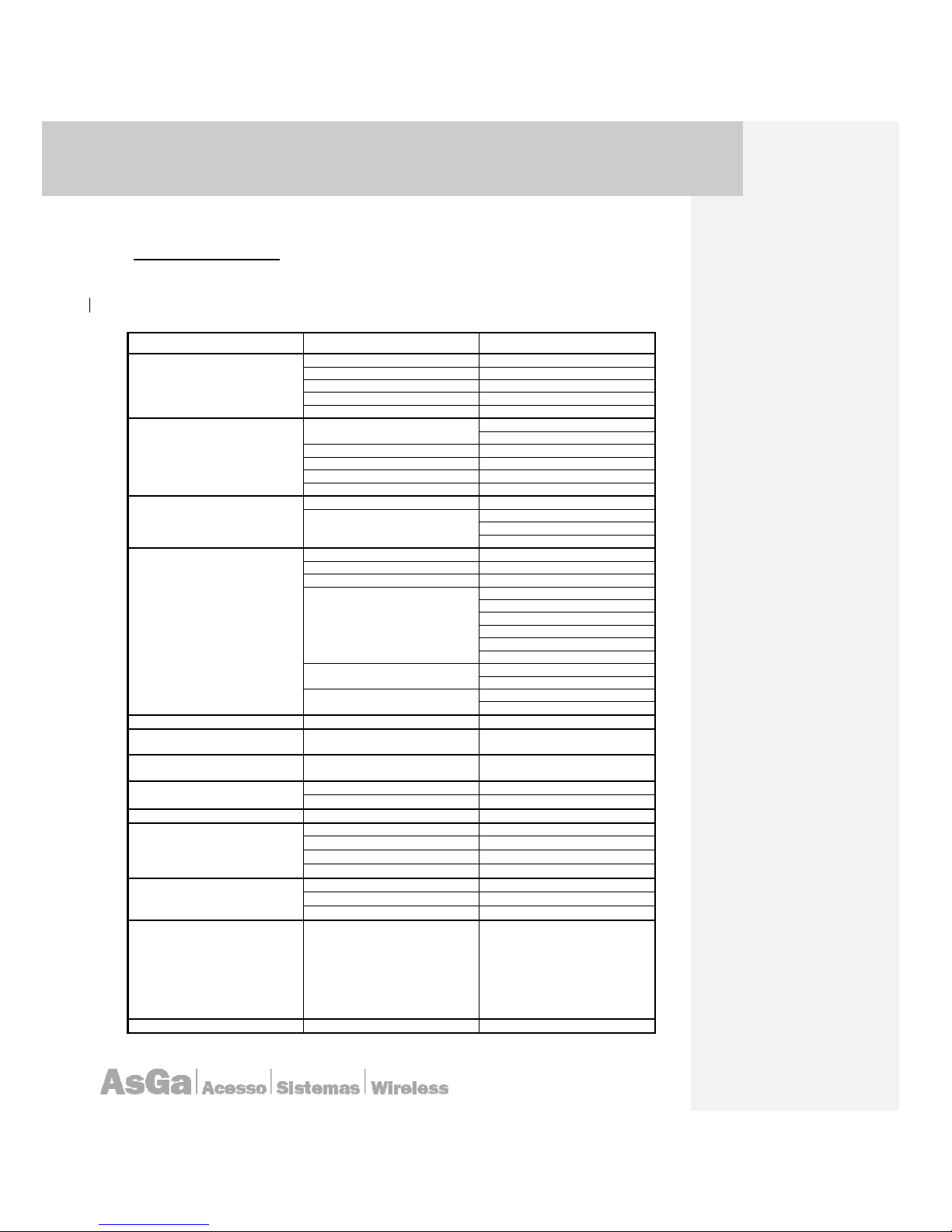
2.1 System Defaults
The switch’s system defaults are provided in the configuration file
“Factory_Default_Config.cfg.” To reset the switch defaults, this file should be set as the startup
configuration file. The following table lists some of the basic system default.
FUNCTION PARAMETER DEFAULT
CONSOLE PORT CONNECTION
Baud Rate 9600 bps
Data Bit 8
Stop Bit 1
Parity N
Console time out Disable 0
AUTHENTICATION
Normal Exec
User Name: none
Password: none
Configuration Level Password: none
RADIUS Disable
SSH V2.0 Disable
Telnet port 23 Disable
SNMP
SNMP V1; V2; V3 Disable
Communities
RO
R/WR
Trap
PORT CONFIGURATION
Admin Status
Enable
Auto negotiation Enable
Flow Control Disable
GiGE (Electrical) Port Capabilities
10 Mbps Half Duplex
10 Mbps Full Duplex
100 Mbps Half Duplex
100 Mbps Full Duplex
1000 Mbps Full Duplex
Flow Control Disable
Xe (10GigE) Optical Port
Capabilities
10 GigE Full Duplex. Fixed.
Flow Control Disable.
Xe (10GigE) XAUI Port
Capabilities
10 GigE Full Duplex. Fixed.
Physical: CX4
RATE LIMITING
In/Out Disable
BROADCAST STORM
SUPPRESSION
In Disable
MULTICAST LIMIT
SUPPRESSION
In Disable
SPANNING TREE PROTOCOL
Mode 802.1D Classic Spanning Tree
Port Fast Disable
ADDRESS MAC TABLE
Aging Time 300 seconds
VIRTUAL LANs VLANs
Default VLAN 1
Port vlan Mode: PVID 1
Frames Acceptable
Untagged
Switch Port Mode Access
MANAGEMENT IP SETTINGS
IP address 0.0.0.0
Mask 255.0.0.0
Default gateway 0.0.0.0
DENIED OF SERVICES
first-fragment-ip-
packets
icmp-attack-check
minimun-icmp-packet-over-size
minimun-tcp-header-allowed
sip-dip-protection
tcp-fragment-attack
tcp-on-invalid-flags
tcp-udp-sp-equal-dp
Enable
Enable
512
20
Enable
Enable
Enable
Eanble
SYSTEM LOG
Status Disable
Table 2.1: System Defaults.

AsGa Light
AsGa LightAsGa Light
AsGa LightBBBBolt 10GigE Switch
olt 10GigE Switcholt 10GigE Switch
olt 10GigE Switch
UUUUser Guide
ser Guideser Guide
ser Guide Configuration
ConfigurationConfiguration
Configuration
12
3 CONFIGURATION
3.1 Command Line Interface
This Guide attempts to make configuration simpler as possible; displaying all AsGOS
command lines necessaries to configure LightBOLT series switches. It covers basic configurations for
Basic Access and all Networking Services provided by the platform.
3.2 Conventions Used in this Guide
Conventions for the syntax and procedures describing how to enter information and how
information is displayed on the console are given in the following table.
CONVENTION DESCRIPTION SYNTAX
command syntax
This monospaced font represents command strings
entered on a command line and sample source code.
show ip ospf
UPPERCASE
A variable parameter. Enter a value according to the
descriptions that follow.
area
AREAID
range
ADDRESS
? question Mark
Used with the square brackets to limit the immediately
following token to one occurrence. Not to be entered as
part of the command.
[parm1|parm2|?parm3]
expands to parm1 parm3
parm1 parm2 (with parm3
occurring once)
lowercase
A keyword parameter. Enter lowercase values exactly as
shown.
show ip ospf
| The vertical bar. Delimits choices; select one from the list.
A.B.C.D|<0-4294967295>
. Dot (period)
Allows the repetition of the element that immediately
follows it multiple times. Not to be entered as part of the
command.
.AA:NN can be expanded
to: 1:01 1:02 1:03.
()
Parenthesis. Delimits optional parameters. Do not enter
parentheses as part of any command
(A.B.C.D|<0-4294967295>)
[]
Square brackets: groups parameters and keywords into a
single unit. Take all parts within these brackets. Do not
enter brackets as part of any command.
[parm2|parm2|parm3]
< >
Angle brackets: enclose a numeric range for a keyword.
Do not enter angle brackets as part of any command.
<0-65535>
description Proportional font gives specific details about a parameter.
=
Equal sign: separates the command syntax from
explanatory text.
PROCESSID = <0-65535>
IFNAME Indicates the name of an interface.
GE1 (For Giga Bit Etherrnet
interfaces) XE1 (For 10Giga
Bit Interfaces)
Note: Unless otherwise stated, press Enter after each command entry.
3.3 Command Line Interface Primer
The AsGOS Command Line Interface (CLI) is a text-based facility similar to most industry
standards command lines interfaces. Each command CLI is usually associated with a specific function
or a common task performing it specificly.
Multiple users can telnet and issue commands using the Exec mode and the Privileged Exec
mode. However, only one user is allowed to use the Configure mode at a time, to avoid multiple users
from issuing configuration commands simultaneously.

AsGa Light
AsGa LightAsGa Light
AsGa LightBBBBolt 10GigE Switch
olt 10GigE Switcholt 10GigE Switch
olt 10GigE Switch
UUUUser Guide
ser Guideser Guide
ser Guide Configuration
ConfigurationConfiguration
Configuration
13
3.3.1 Command Line Help
The AsGOS CLI contains a text-based help facility. Access this help by typing in the full or
partial command string then typing “?”. The AsGOS CLI displays the command keywords or
parameters plus a short description.
Note: Some of our command examples showed here are base on features that will be released. All of
them must be taken as typographic examples only.
For example, at the CLI command prompt, type “show ?” (the CLI does not display the question
mark). The CLI displays this keyword list with short descriptions for each keyword:
bgpd# show
debugging Debugging functions (see also 'undebug')
history Display the session command history
ip IP information
memory Memory statistics
route-map route-map information
running-config running configuration
startup-config Contents of startup configuration
version Displays AsGOS version
3.3.2 Syntax Help
The AsGOS CLI can complete the spelling of command or parameter keywords. Begin typing
the command or parameter then press TAB. At the CLI command prompt type sh:
AsGOS> sh
Press TAB. The CLI shows:
AsGOS> show
If the command or parameter partial spelling is ambiguous, the AsGOS CLI displays the
choices that match the abbreviation. Type show i. Press TAB. The CLI shows:
AsGOS> show i
interface ip
AsGOS> show i
The interface displays the interface and ip keywords. Type “n” to select interface and press
TAB. The CLI shows:
AsGOS> show in
AsGOS> show interface
Type ? and the CLI shows the list of parameters for the show interface command.
[IFNAME] Interface name
AsGOS> show interface
This command has but one positional parameter, an interface name. Supply a value for the
IFNAME parameter.

AsGa Light
AsGa LightAsGa Light
AsGa LightBBBBolt 10GigE Switch
olt 10GigE Switcholt 10GigE Switch
olt 10GigE Switch
UUUUser Guide
ser Guideser Guide
ser Guide Configuration
ConfigurationConfiguration
Configuration
14
3.3.3 Command Abbreviations
The AsGOS CLI accepts abbreviations for commands. For example:
sh in Ge7
Is the abbreviation for the “show interface command”.
3.3.4 Command Line Errors
If the switch does not recognize the command after ENTER is pressed, it displays the following
message:
% Unknown command.
If a command is incomplete it displays the following message:
% Command incomplete.
Some commands are too long for the display line and can wrap in mid-parameter or mid-keyword if
necessary.
3.4 Modes Common to Protocols
Exec: This mode, also called the View mode, is the base mode from where users can perform basic
commands like show, exit, quit, help, list, and enable.
Privileged Exec: This mode, also called the Enable mode, allows users to perform debugging
commands, the write commands (for saving and viewing the configuration), show commands, and so
on.
Configure: Sometimes referred to as Configure Terminal, this mode serves as a gateway into the
Interface, AsGOS, Line, Route Map, Key Chain and Address Family modes.
Interface: This mode (or context) is used to configure protocol-specific settings for a particular
interface.
Line: This mode (or context) makes available access-class commands.

AsGa Light
AsGa LightAsGa Light
AsGa LightBBBBolt 10GigE Switch
olt 10GigE Switcholt 10GigE Switch
olt 10GigE Switch
UUUUser Guide
ser Guideser Guide
ser Guide Configuration
ConfigurationConfiguration
Configuration
15
3.5 Command Negation
Some commands can be negated by using a no keyword. Depending on the command or
the parameters, command negation can mean the disabling of one entire feature for the
AsGOS/switch or the disabling of that feature for a specific ID, interface or address.
In the following example, negation is for the base command only. The negated form does
not take any parameter.
default-metric <1-16777214>
no default-metric
3.6 Format used for Command Description
The following lines show us how commands will be represented in the context of this manual:
Command name
Description of the command. What the command does and when should it be used.
Command Syntax
Sample command name mandatory-parameters (OPTIONAL-PARAMETERS)
Default
The status of the command before it is executed. Is it enabled or disabled by default.
Command Mode
Name of the command mode in which this command is to be used. Such as, Exec, Privilege Exec,
Configure mode and so on.
Usage
This section is optional. It describes the the usage of a specific command and the interactions
between parameters. It also includes appropriate sample outputs for show commands.
Example
Used if needed to show the complexities of the command syntax.
Related Commands
This section is optional and lists those commands that are of immediate importance.
Equivalent Commands
This section is optional and lists commands that accomplish the same function.
Validation Commands
This section is optional and lists commands that can be used to validate the effects of other
commands.
3.7 Initial Configuration
The switch includes a built-in network management agent based on a CLI Industry default
access method. A PC may be connected directly to the switch for configuration and all of its features
can be monitored and configured via this command line interface (CLI). In addition to CLI access
method the system has a complete SNMP option; including those defined on SNMP V.3 RFC 2575
(View based Access Control Model for SNMP).
The CLI program can be accessed by a direct connection to the RS-232 serial console port
on the switch; or remotely by a Telnet or SSH connection over the network. For any remote operation
AsGa Light
AsGa LightAsGa Light
AsGa LightBBBBolt 10GigE Switch
olt 10GigE Switcholt 10GigE Switch
olt 10GigE Switch
UUUUser Guide
ser Guideser Guide
ser Guide Configuration
ConfigurationConfiguration
Configuration
16
you need to configure an IP management address. The IP address for this switch is unassigned by
default. To change this address, see “Setting Management IP address” on page 25.
The switch, CLI interface configuration program agent allows you to perform the following
management functions:
• Set user names and passwords.
• Set an IP interface for a management VLAN.
• Configure SNMP parameters.
• Enable/disable any port.
• Set the speed/duplex mode for any port.
• Configure up to 4096 IEEE 802.1Q VLANs.
• Upload and download system software via TFTP.
• Upload and download switch configuration files via TFTP.
• Configure Spanning Tree parameters for all STPx supported.
• Enable port mirroring.
• Set broadcast storm control on any port.
• Display system information and statistics.
• Others.
3.8 Connecting to the switch
3.8.1 Local Configuration
The switch provides an RS-232 serial port that enables a connection to a PC or terminal for
monitoring and configuring the switch. To do this you will need a RS232 (no cross over cable) cable;
attach a VT100-compatible terminal or a PC running your favorite terminal emulation program with the
following parameters configured:
• Select the appropriate serial port (COM port 1 or COM port 2).
• Set the profile to the default switch profile.
• Once you have set up the terminal correctly, the console login screen will be displayed.
• Refer to “Line Commands” for a complete description of console configuration options.
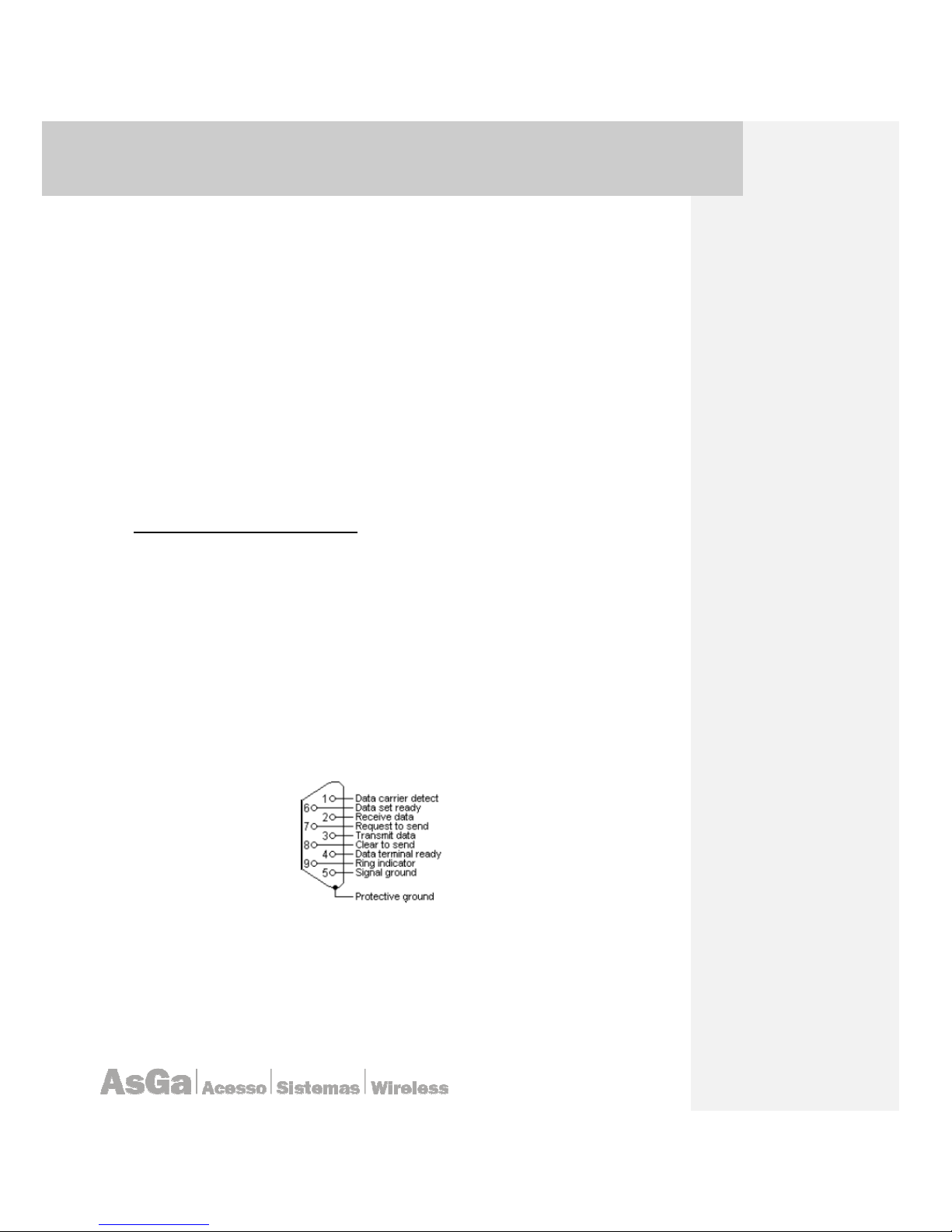
The following picture show the DB9 switch “Pin out”:
3.8.2 Remote Connections
By default your LightBolt switch does not accept any remote configuration neither telnet nor
ssh. You need specifically enable those features trough configuration mode. The following lines
describe those commands in order to enable the Telnet service.
AsGa Light
AsGa LightAsGa Light
AsGa LightBBBBolt 10GigE Switch
olt 10GigE Switcholt 10GigE Switch
olt 10GigE Switch
UUUUser Guide
ser Guideser Guide
ser Guide Configuration
ConfigurationConfiguration
Configuration
17
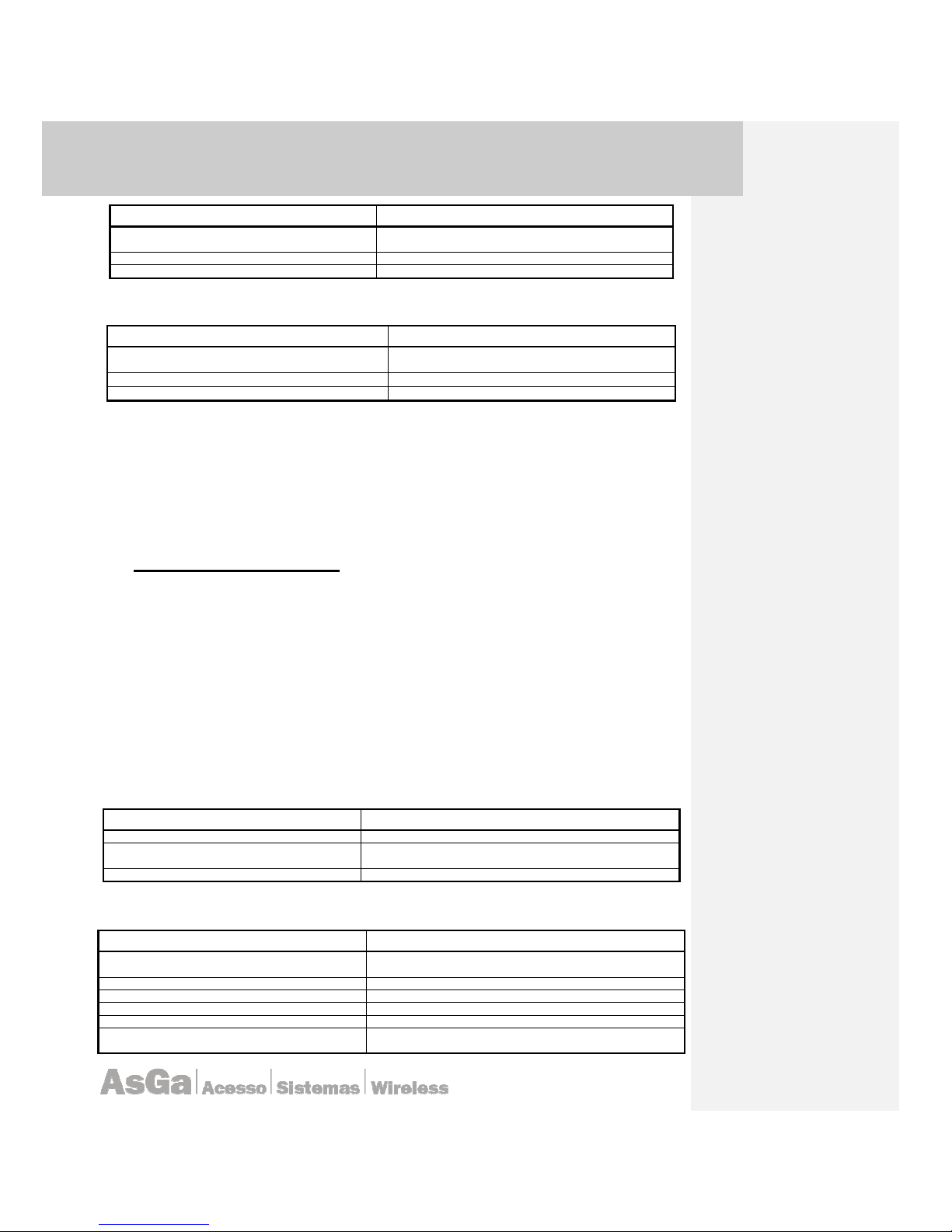
COMMAND DESCRIPTION
AsGa> enable
To enter in configuration mode ingress the enable command
and press enter.
AsGa# service telnet (enable | Disable)
Enable or disable the Telnet Service
AsGa# wr
Save the current configuration
SSH Service:
COMMAND
DESCRIPTION
AsGa> enable
To enter in configuration mode ingress the enable
command and press enter.
AsGa# service ssh (enable | disab
le)
Enable or Disable the SSH Service
AsGa# wr
Save the current configuration
As well to gain access to onboard management agent via a network connection, you must first
configure it with a valid IP address, subnet mask, and route (when it is needed) using a console
connection. The IP address for this switch is unassigned by default; see “Setting Management IP
address” on page 25.
This switch supports five simultaneous Telnet sessions. After configuring the switch’s IP
parameters, you can access the onboard configuration program from anywhere within the attached
network. The onboard configuration program can be accessed using Telnet (port 23 by default) or
SSH from any computer attached to the network.
3.9 Configuring the Switch
3.9.1 Basic Configuration – Console Connection
The CLI program provides different command levels — normal access level (Normal Exec)
View mode; privileged access level (Privileged Exec) and configuration mode. The commands
available at the Normal Exec level are a limited subset of those available at the Privileged Exec level
and allow you to only display information and use basic utilities. To fully configure the switch
parameters, you must access the CLI at the privileged Exec level. Access to both CLI levels are
controlled by users names and passwords. The switch has no default user name and password
configured.
Connected to the console port to initiate your console connection, just press <Enter>. At the
first time you will not be prompted for a user name and password. You will have the default prompt
name witch will be “AsGa> “ witch indicate the normal Exec mode operation (or View mode).
At this level you can enter at the configuration mode issuing the following commands:
COMMAND DESCRIPTION
AsGa>
Default hostname and prompt will be displayed
AsGa> Enable
To enter in configuration mode ingress the
enable
command and
press enter.
AsGa#
Now you are into configuration mode or privileged mode.
If you have configured a user name and password you will be prompted:
COMMAND DESCRIPTION
After connect your terminal you will be prompted for a user name
and password.
User name:
Enter your configured User name.
Password:
Enter Your Configured Pass.
AsGa>
Default hostname and password.
AsGa> enable
Now you can issue the command
enable
.
AsGa#
The prompt will change to “#”. Now you are into the privileged
mode or configuration mode.

AsGa Light
AsGa LightAsGa Light
AsGa LightBBBBolt 10GigE Switch
olt 10GigE Switcholt 10GigE Switch
olt 10GigE Switch
UUUUser Guide
ser Guideser Guide
ser Guide Configuration
ConfigurationConfiguration
Configuration
18
3.9.2 Displaying system configuration
In order to verify your current configuration you need to type the command “show
running” under the privileged Exec level (enable mode). This command displays your
configuration stored into NVRAM and actually running on your system. A typical view of this command
can be summarized:
AsGa#sh run
!
no service password-encryption
!
hostname AsGa
!
spanning-tree mst config
bridge instance 1 vlan 100
bridge instance 1 vlan 300
bridge instance 2 vlan 20
bridge region test
!
maximum-paths 8
bridge protocol mstp
bridge acquire
vlan classifier rule 1 ipv4 40.40.40.40/24 vlan 300
vlan classifier rule 2 mac 00.0c4.012 vlan 300
vlan classifier rule 3 proto 8192 encap ethv2 vlan 300
vlan classifier group 1 add rule 1
vlan classifier group 1 add rule 2
vlan classifier group 1 add rule 3
bridge spanning-tree errdisable-timeout interval 1
bridge cisco-interoperability enable
!
vlan database
vlan 20 bridge name TEST2
vlan 20 bridge state enable
vlan 100 bridge name TEST
vlan 100 bridge state enable
vlan 300 bridge name TEST3
vlan 300 bridge state enable
vlan 4094 bridge name DEFAULT-VLAN
vlan 4094 bridge state enable
!
interface ge1
switchport
switchport mode access
switchport access vlan 100
flowcontrol send on
flowcontrol receive on
bridge-group instance 1
spanning-tree portfast
!
interface ge2
switchport
bridge-group
switchport mode access
switchport access vlan 20
bridge-group instance 2
spanning-tree portfast

AsGa Light
AsGa LightAsGa Light
AsGa LightBBBBolt 10GigE Switch
olt 10GigE Switcholt 10GigE Switch
olt 10GigE Switch
UUUUser Guide
ser Guideser Guide
ser Guide Configuration
ConfigurationConfiguration
Configuration
19
!
interface ge3
switchport
switchport mode access
switchport access vlan 100
bridge-group instance 1
spanning-tree portfast
!
interface ge4
switchport
switchport mode access
vlan classifier activate 1
bridge-group instance 1
!
interface ge5
!
interface ge6
!
interface ge7
!
interface ge8
!
interface ge9
!
interface ge10
!
interface ge11
switchport
switchport mode access
!
interface ge12
switchport
switchport mode trunk
switchport mode trunk ingress-filter enable
switchport trunk allowed vlan add 300
bridge-group instance 1
bridge-group instance 2
!
interface ge13
!
interface ge14
!
interface ge15
!
interface ge16
!
interface ge17
!
interface ge18
!
interface ge19
!
interface ge20
switchport
switchport mode access
switchport mode access ingress-filter enable
switchport access vlan 300
flowcontrol send on

AsGa Light
AsGa LightAsGa Light
AsGa LightBBBBolt 10GigE Switch
olt 10GigE Switcholt 10GigE Switch
olt 10GigE Switch
UUUUser Guide
ser Guideser Guide
ser Guide Configuration
ConfigurationConfiguration
Configuration
20
flowcontrol receive on
bridge-group instance 1
spanning-tree portfast
!
interface ge21
switchport
switchport mode access
switchport access vlan 300
spanning-tree portfast
!
interface ge22
!
interface ge23
switchport
switchport mode trunk
switchport mode trunk ingress-filter enable
switchport trunk allowed vlan add 20
switchport trunk allowed vlan add 100
switchport trunk allowed vlan add 300
switchport trunk allowed vlan add 4094
switchport trunk native vlan 4094
bridge-group instance 1
bridge-group instance 2
!
interface ge24
switchport
switchport mode trunk
switchport mode trunk ingress-filter enable
switchport trunk allowed vlan add 20
switchport trunk allowed vlan add 100
switchport trunk allowed vlan add 300
switchport trunk allowed vlan add 4094
bridge-group instance 1
bridge-group instance 2
!
interface lo
mtu 1500
ip address 127.0.0.1/8
ip address 30.30.30.30/24 secondary
!
interface vlan1.1
!
interface vlan1.20
!
interface vlan1.100
ip address 10.10.10.10/24
!
interface vlan1.300
!
interface vlan1.4094
!
line con 0
exec-timeout 0 0
login
line vty 0 4
exec-timeout 0 0
login local
!
AsGa Light
AsGa LightAsGa Light
AsGa LightBBBBolt 10GigE Switch
olt 10GigE Switcholt 10GigE Switch
olt 10GigE Switch
UUUUser Guide
ser Guideser Guide
ser Guide Configuration
ConfigurationConfiguration
Configuration
21
end
AsGa#
3.9.3 Displaying system inventory
The command “show inventory” shows all basic system information including MAC base
system address; software and hardware versions; manufacturing data; etc. A typical view of this
command is:
System Inventory: Lightbolt 28304E
Mac Address: 00:14:fa:00:29:30
Description: Production Sample
Product code: 15097
Serial number: 1
Manufacturing Date: 01/04/2008
Hardware Version: 15
Firmware Version: 1
System Version: N/A
Startup Version: 1.0.0-RC1
AsGOS Version: 1.0.0-RC5
Product Notes: Not for sale
Resets: 113
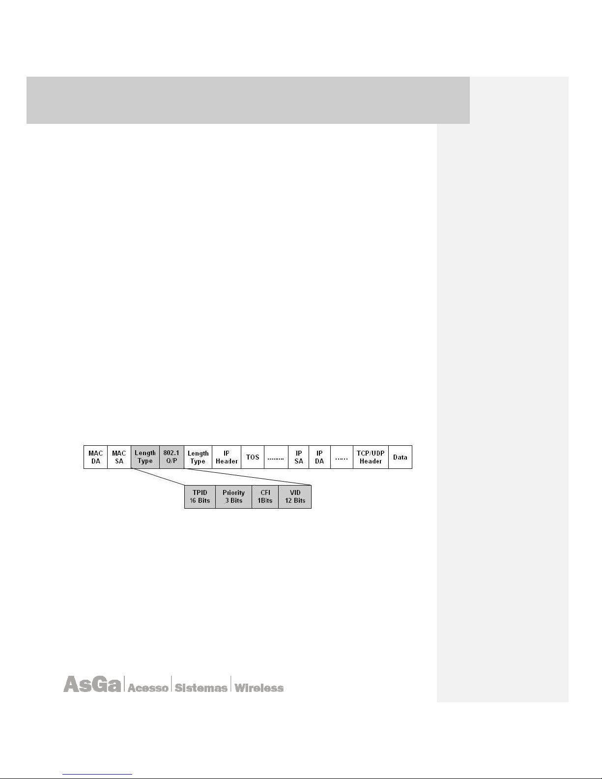
3.9.4 Defining 802.1Q VLAN
VLANs are a mechanism to allow network administrators to create logical broadcast domains
that can span across a single switch or multiple switches, regardless of physical proximity. This
function is useful to reduce the size of broadcast domains or to allow groups or users to be logically
grouped without the need to be physically located in the same place.
Your LightBolt switch permits up to 4095 VLANs to be defined on a single switch. The
following figure shows a single VLAN tagued packet:
3.9.4.1 Creating VLANs into the Switch Database
Use the vlan database into configuration mode command to add a VLAN and enter the configvlan mode. Use the no statement of this command to delete the VLAN.
vlan vlan-id {enable|disable}|[name vlan-name][state {suspend|active}
no vlan vlan-id
vlan-id ID: of the configured VLAN. Valid IDs are from 1 to 4095. Do not enter leading zeros.
Name: vlan-name (Optional): Specify the VLAN name, an ASCII string from 1 to 32
characters.
State: {suspend | active} (Optional) Specify the VLAN state:
• If active, the VLAN is operational.

AsGa Light
AsGa LightAsGa Light
AsGa LightBBBBolt 10GigE Switch
olt 10GigE Switcholt 10GigE Switch
olt 10GigE Switch
UUUUser Guide
ser Guideser Guide
ser Guide Configuration
ConfigurationConfiguration
Configuration
22
• If suspend, the VLAN is suspended. Suspended VLANs do not traffic
packets.
• Create the VLANs into the VLAN switch database:
COMMAND DESCRIPTION
AsGOS (config)# vlan database
Enter the
VLAN
configuration mode.
AsGOS (config-vlan)# vlan 5 state enable
Enable VLAN number 5. Specifying the enable
state allows forwarding of frames on this VLAN-
aware bridge.
AsGOS (config-vlan)# exit
Exit the VLAN configuration mode and enter
Configuration mode.
3.9.5 Switch Port Roles
Physical ports in a switch can have two defined roles:
switched ports: ports witch can not accept an IP address or
routed ports: ports witch can accept an IP address.
Note: By default all ports are switched (no routed) access ports with the default per port VLAN ID
(PVID) equal to one (PVID=1). By default the system run classical STP on all those access port.
Use the switchport interface configuration command with no keywords to put an interface
that is in Layer 3 mode into Layer 2 mode for Layer 2 configuration. Use the no statement of this
command to put an interface in Layer 3 mode.
switchport
no switchport
Use the no switchport command (without parameters) to set the interface to the routedinterface status and to erase all Layer 2 configurations. You must use this command before assigning
an IP address to a routed port.
COMMAND DESCRIPTION
AsGa>config t
Enter into configuration mode.
AsGa#interface ge1
Enter into interface ge1 configuration mode.
AsGa(interface)#
Now you are into the interface configuration mode.
AsGa(interface)# swtchport
Put the interface into the default switchport mode.
AsGa(interface)#end
Exit from interface configuration mode.
AsGa# wr
Save the configuration.
COMMAND DESCRIPTION
AsGa>config t
Enter into configuration mode
AsGa#interface ge1
Enter into interface ge1 configuration mode.
AsGa(interface)#
Now you are into the interface configuration mode.
AsGa(interface)# NO swtchport
Put the interface into the routed port mode, ready to
accept an IP address.
AsGa(interface)#end
Exit from interface configuration mode.
AsGa# wr
Save the configuration.

AsGa Light
AsGa LightAsGa Light
AsGa LightBBBBolt 10GigE Switch
olt 10GigE Switcholt 10GigE Switch
olt 10GigE Switch
UUUUser Guide
ser Guideser Guide
ser Guide Configuration
ConfigurationConfiguration
Configuration
23
3.9.6 Switchport Mode
When the switch receives a frame, it classifies the frame in one of two ways. If the frame is
untagged, the switch assigns the frame to an associated VLAN (based on the default VLAN ID of the
receiving port). But if the frame is tagged the switch use the Taggued VLAN ID to identify the port
broadcast domain for the frame.
In order to identify the ports on wich the frame must be sent first at all you need to define the
switch port mode of a port.
Ports can be 3 types:
• Access Ports.
• Trunk Ports.
• Hibrid ports.
Use the switchport mode interface configuration command to configure the mode of a port. Use
the <no> statement of this command to reset the mode to the appropriate default for the device.
switchport mode {access | trunk | hybrid}
no switchport mode {access| trunk | hybrid}
Access: Set the port to access mode. The port is set to access unconditionally and operates as a
nontrunking, single VLAN interface that sends and receives nonencapsulated (non-tagged) frames.
An access port can be assigned to only one VLAN.
Trunk: Set the port to trunk unconditionally. The port is a trunking VLAN Layer-2 interface. The port
sends and receives encapsulated (tagged) frames that identify the VLAN of origination. A trunk is a
point-to-point link between two switches or between a switch and a router.
Hibrid: This mode set the trunk in an hybrid mode wich means that the port acting as a trunk has a
default VLAN for all those packets that arrive at the port untagged. Under this mode the user must
specify the untagged VLAN for all those arriving non tagged packets. Packet going outward for the
specified VLAN ID will go from this trunk in an untagged form.
• Setting an interface into switched port mode access:
COMMAND DESCRIPTION
AsGa>config t
Enter in configuration mode.
AsGa#interface ge1
Enter in interface ge1 configuration mode.
AsGa(interface)#
Now you are into the interface configuration mode.
AsGa(interface)# swtchport mode access
Put the interface in the accces switch port mode.
AsGa(interface)#end
Exit from interface configuration mode.
AsGa# wr
Save the configuration.
• Setting an interface in switched port mode trunk:
COMMAND DESCRIPTION
AsGa>config t
Enter in configuration mode.
AsGa#interface ge1
Enter in interface ge1 configuration mode.
AsGa(interface)#
Now you are into the interface configuration mode.
AsGa(interface)# swtchport mode trunk
Put the interface in the trunk switch port mode.
AsGa(interface)#end
Exit from interface configuration mode.
AsGa# wr
Save the configuration.

AsGa Light
AsGa LightAsGa Light
AsGa LightBBBBolt 10GigE Switch
olt 10GigE Switcholt 10GigE Switch
olt 10GigE Switch
UUUUser Guide
ser Guideser Guide
ser Guide Configuration
ConfigurationConfiguration
Configuration
24
3.9.7 Assigning a VLAN to an Access port
Use the “switchport access” interface configuration command to configure a port as a VLAN
assigned static-access port. If the mode is set to access, the port operates as a member of the
configured VLAN.
switchport access vlan {vlan-id }
no switchport access vlan
COMMAND DESCRIPTION
AsGa>config t
Enter in configuration mode.
AsGa#interface ge1
Enter in interface ge1 configuration mode.
AsGa(interface)#
Now you are in the interface configuration mode.
AsGa(interface)# swtchport access vlan 300
Assign Pert Port VLAN ID to an access port.
AsGa(interface)#end
Exit from interface configuration mode.
AsGa# wr
Save the configuration.
3.9.8 Adding VLANs to a Trunk Port
Ports can be access port or trunk port. The table shows the steps necessaries for adding a
VLAN in an trunk port.
• Enabling all VLANs on a trunk port.
COMMAND DESCRIPTION
AsGOS# configure terminal
Enter the Configure mode.
AsGOS(config)# Interface GE24
Enter into the Ge24 Interface context.
AsGOS (config_if)# switchport mode trunk
Set the switching characteristics of this interface to
trunk mode.
AsGOS (config_if)#
switchport
trunk allowed
vlan all.
Enable all VLANs on this trunk port.
AsGOS (config-if)# exit
Exit the interface configuration mode and enter
configuration mode.
• Adding a particular VLAN to a trunk port.
COMMAND DESCRIPTION
AsGOS# configure terminal
Enter the
Configure
mode.
AsGOS(config)# Interface GE24
Enter into the Ge24 Interface context.
AsGOS (config_if)# switchport mode trunk
Set the switching characteristics of this interface to
trunk mode.
AsGOS (config_if)# switchport trunk add
vlan 100
Enable VLAN ID 100 on this trunk port. Any other
vlan than 100 will be filtered by this trunk port.
AsGOS (config-if)# exit
Exit the interface configuration mode and enter
configuration mode.
3.9.9 Displaying VLAN information
In order to display the VLAN port assignment you need to issue the command “show vlan all”
specifying the bridge number. The system will show the following list:

AsGa Light
AsGa LightAsGa Light
AsGa LightBBBBolt 10GigE Switch
olt 10GigE Switcholt 10GigE Switch
olt 10GigE Switch
UUUUser Guide
ser Guideser Guide
ser Guide Configuration
ConfigurationConfiguration
Configuration
25
AsgOS#show vlan all
Bridge VLAN ID Name State Member ports
(u)-Untagged,
(t)-Tagged
================================================================
1 1 default ACTIVE
ge1(u)ge2(u)ge3(u)
ge4(u)ge5(u)ge6(u)
ge7(u)ge8(u)ge9(u)ge10(u)
ge11(u)ge12(u)ge13(u)ge14(u)
ge15(u)ge16(u)ge17(u)ge18(u)
ge19(u)ge20(u)ge21(u)ge22(u)
ge23(u)ge24(u)
xe1(u)xe2(u)xe3(u)xe4(u)
3.9.10 Setting Management IP address
You must define an IP address for the switch to obtain management access through a external
network. At this time you can set the management IP address manually. No DHCP is supported.
Remote management is taken from any IP interface defined into the switch, Routed IP
interfaces and Switched Virtual interfaces (SVI´s) are suitable of receive an IP address. Those IP
address can be used as Management interfaces as they appear as directed connected IP interfaces
to the global L3 routing table.
Use the ip address interface configuration command to set an IP address for the Layer 2 switch
or an IP address for each switch virtual interface (SVI) or routed port on the Layer 3 switch.
Assuming that your LightBolt switch has just one default vlan (VLAN1) and its respective
switched virtual interface (SVI) VLAN1.1; the following commands shows how to set up an IP address
for these particular default SVI; wich can be reached from any interface belonging to those VLAN.
COMMAND DESCRIPTION
AsGa>config t
Enter in configuration mode
AsGa#interface VLAN1.1
Enter in interface vlan1.1 configuration mode.
VLAN1.1 is the default switched virtual interface witch
represent the routed interface for the default VLAN 1
AsGa(interface)#
Now you are in the interface configuration mode
AsGa(interface)#ipaddress x.x.x.x/y
Enter the IP address
AsGa(interface)#end
Exit from interface configuration mode
AsGa# wr
Save the configuration
In Order to negate this IP address uses the <no> statement of this command. The example use
the SVI VLAN1.1 witch is created by default into the system. Remember that those SVI´s are created
by the system each time that you define a VLAN into the VLAN database. By default those SVI´s does
not contain any IP address.
3.9.11 Specifying Host Name
To assign your host name use the following steps at your privileged command line.
COMMAND DESCRIPTION
AsGOS# configure terminal
Enter the
Configure
mode.
AsGOS(config)#hostname LighetBolt
Specify your host name.
LightBolt (config)#
Your host name will appear as a new prompt in your system.
Exit from configuration mode.
LightBolt# Write
Save your changes into permanent memory.

AsGa Light
AsGa LightAsGa Light
AsGa LightBBBBolt 10GigE Switch
olt 10GigE Switcholt 10GigE Switch
olt 10GigE Switch
UUUUser Guide
ser Guideser Guide
ser Guide Configuration
ConfigurationConfiguration
Configuration
26
3.10 Managing file System
3.10.1 File types
Your LightBolt System storage different file types. By default the system has an image file that
runs your current system, this image file is identified by the extension .BIN. You can maintain up to 3
software versions in your system. Also Binary (BIN) files can be from three types:
• AsGos: Binary Files that contain all mayors control planes and switching/routing software. Naming
convention for this file is:
LightBolt-28322-E1-L2-AsGOS-1.0.0-RC4.bin
• System: Binary files that contain no switching / routing control planes software but have some
other software pices. Naming convention for this file is:
LightBolt-28322-E1-L2-System-1.0.0-RC2.bin
• Sanity: Binary files that contain sanity check code. Naming convention for this file is:
LightBolt-28322-E1-L2-Sanity-1.0.0-RC1.bin
In addition to this system file there are configuration files identified by the extension .CONF this
file type storage in a plain text format all configuration rules. There is no limit to the quantity of
configuration files sorted into your system. Just one will be active at time.
Another file type is the .LOG file this file type storage all system sanity test information under
this extension you can find a default file wich name is production.log this file storage all factory
sanity log, this file is a read only file and can not be deleted. The user can decide at startup time run a
new sanity test; its result will be storage under a new file name.
LighBOLT flash system has a flash memory capacity of 32 Mb. This memory can not be
formatted by the user. Use the dir command at privilege level to inspect your file system.
The following shows a typical file system:
AsGa-LAB-1#dir
3.8M Wed Jan 2 01:15:59 2002 LightBolt-28322-E1-L2-AsGOS-1.0.0-RC4.bin
3.8M Mon Jul 21 17:13:49 2036 LightBolt-28322-E1-L2-AsGOS-1.0.0---RC4.bin
1.4M Wed Jan 2 01:18:32 2002 LightBolt-28322-E1-L2-Sanity-1.0.0-RC1.bin
708.8k Mon Jul 21 17:16:06 2036 LightBolt-28322-E1-L2-System-1.0.0---RC4.bin
708.8k Wed Jan 2 01:16:49 2002 LightBolt-28322-E1-L2-System-1.0.0-RC2.bin
3.5k Thu Jul 24 10:59:22 2036 default.conf
0 Mon Jul 14 17:34:08 2036 julio
Flash disk space:
Used Available Use%
11.8M 31.2M 27%
3.10.2 Loading new files into your system
In order to load files into your system you have a total free disk space of 32 Mb. The system
load files into this free memory space using TFTP transfer; to do it you need to make available a
TFTP server and issue the following commands:
For copying from a TFTP server to system memory:
AsGa# copy <TFTP server address> <file name> flash
For copying to TFTP server:
AsGa Light
AsGa LightAsGa Light
AsGa LightBBBBolt 10GigE Switch
olt 10GigE Switcholt 10GigE Switch
olt 10GigE Switch
UUUUser Guide
ser Guideser Guide
ser Guide Configuration
ConfigurationConfiguration
Configuration
27
AsGa# copy <file name> <TFTP server address>
3.10.3 Saving and restoring system Files
In order to store or restore bin images or different configuration files you must use the previous
mentioned commands, You can change your booting image at any time by assigning it as a new
booting image, next reload time it will take effect.
All TFTP saved configuration files can be loaded at any time and will take effect after you
configure as a configuration boot file, at next booting time it will take effect.
3.10.4 Configure your booting process.
Your LightBolt switch boot using an image file plus a configuration file. There is a configuration
file named default.txt wich is your default system configuration file but you can assign at any time and
any combination of booting files plus a bin image to boot your system. To display your booting
information use of the following commands:
ASGA_1#sh boot
Config File:
Startup: AsGa-conf-1
Running: AsGa-conf-1
Last Modified: Mon Apr 7 12:56:13 2036
AsGOS Image:
Startup: LightBolt-28322-E1-L2-AsGOS-1.0.0-RC4.bin
Running: LightBolt-28322-E1-L2-AsGOS-1.0.0-RC4.bin
Last Modified: Thu Apr 3 08:34:12 2036
System Image:
Startup: LightBolt-28322-E1-L2-System-1.0.0-RC2.bin
Running: LightBolt-28322-E1-L2-System-1.0.0-RC2.bin
Last Modified: Tue Apr 1 08:45:23 2036
Sanity Image:
Startup: LightBolt-28322-E1-L2-Sanity-1.0.0-RC1.bin
Last Modified: Tue Apr 1 08:45:23 2036
To change your actual booting configuration files use this commands:
• Changing your AsGOS bin File
COMMAND DESCRIPTION
AsGOS#
configure terminal
Enter the Configure mode.
AsGOS(config)# boot
LightBolt-28322-E1-
L2-AsGOS-1.0.0-RC5.bin
Specify the booting AsGOS image file name.
AsGOS (config)# exit
Exit from configuration mode.
LightBolt#
Write
Save your changes into permanent memory.

AsGa Light
AsGa LightAsGa Light
AsGa LightBBBBolt 10GigE Switch
olt 10GigE Switcholt 10GigE Switch
olt 10GigE Switch
UUUUser Guide
ser Guideser Guide
ser Guide Configuration
ConfigurationConfiguration
Configuration
28
• Changing your config File
COMMAND DESCRIPTION
AsGOS# configure terminal
Enter the Configure mode.
AsGOS(config)# boot config
AsGa-conf-2
Specify the booting configuration file name.
AsGOS (config)#
exit
Exit from configuration mode.
LightBolt#
Write
Save your changes into permanent memory
.
• Changing your System File
COMMAND DESCRIPTION
AsGOS# configure terminal
Enter the Configure mode.
AsGOS(config)# boot system
LightBolt-
28322-E1-L2-System-1.0.0-RC3.bin
Specify the booting system file name.
AsGOS (config)# exit
Exit from configuration mode.
LightBolt# Write
Save your changes into permanent memory.
Under those changes the show boot command will display the show boot command will display
the following changes:
ASGA_1#sh boot
Config File:
Startup: AsGa-conf-2
Running: AsGa-conf-2
Last Modified: Mon Apr 7 12:56:13 2036
AsGOS Image:
Startup: LightBolt-28322-E1-L2-AsGOS-1.0.0-RC5.bin
Running: LightBolt-28322-E1-L2-AsGOS-1.0.0-RC4.bin
Last Modified: Thu Apr 3 08:34:12 2036
System Image:
Startup: LightBolt-28322-E1-L2-System-1.0.0-RC3.bin
Running: LightBolt-28322-E1-L2-System-1.0.0-RC2.bin
Last Modified: Tue Apr 1 08:45:23 2036
Sanity Image:
Startup: LightBolt-28322-E1-L2-Sanity-1.0.0-RC1.bin
Last Modified: Tue Apr 1 08:45:23 2036
On next booting time the switch will load the new AsGOS; System and config files.
3.11 Configuring System Logs
All system actions can be logged in an internally file for future analysis. All Log files when
created and activated are first stored into RAM and must be explicitly copied to flash by the
user. Log can be sent to a standard view or a sys log server.
AsgOS(config)#log ?
file Logging to file
monitor Copy debug output to the current terminal line
stdout Logging goes to stdout
syslog Logging goes to syslog
trap Limit logging to specified level
AsGa Light
AsGa LightAsGa Light
AsGa LightBBBBolt 10GigE Switch
olt 10GigE Switcholt 10GigE Switch
olt 10GigE Switch
UUUUser Guide
ser Guideser Guide
ser Guide Configuration
ConfigurationConfiguration
Configuration
29
3.11.1 System Log Configuration
Logging is enabled each time you specify a logging method. When logged it can send
messages to specific locations in addition to the console. Under privileged EXEC mode, use one or
more of the following commands to specify the locations that receive messages:
• Logging to a file:
COMMAND DESCRIPTION
AsGOS#
configure terminal
Enter in the
Configure
mode.
AsGOS(config)# log <file>
Specify the logging file name.
AsGOS (config)# exit
Exit from configuration mode.
LightBolt# Write
Save your changes into permanent memory
.
Your file will be stored in RAM; if you need save it you need to type issue the following command:
COMMAND DESCRIPTION
AsGOS#
write log
Write your log file into permanent memory.
• Logging to a log server:
COMMAND
DESCRIPTION
AsGOS# configure terminal
Enter in the
Configure
mode.
AsGOS(config)# log syslog <IP address>
Specify the logging server IP address.
AsGOS (config)# exit
Exit from configuration mode.
LightBolt# Write
Save your changes into permanent memory
.
• Logging to a log monitor
COMMAND
DESCRIPTION
AsGOS# configure terminal
Enter in the
Configure
mode.
AsGOS(config)# log
monitor
Specify loggining method eq monitor
AsGOS (config)# exit
Exit from configuration mode.
3.12 Configuring your console port
You can access the onboard configuration program by attaching a VT100 compatible device to
the switch’s serial console port. Management access is controlled by the console port parameters,
including a password, timeouts, and basic communication settings.
3.12.1 Console attributes
Data Bits: Sets the number of data bits per character that are interpreted and generated by the
console port. If parity is being generated, specify 7 data bits per character. If no parity is required,
specify 8 data bits per character. (Default: 8 bits).
Parity: Defines the generation of a parity bit. Communication protocols Provided by some terminals
can require a specific parity bit setting. Specify Even, Odd, None, Mark or space. (Default: None)
Speed: Sets the terminal line’s baud rate for transmit (to terminal) and receive (from terminal). Set
the speed to match the baud rate of the device connected to the serial port. (Default: 9600 bps).
Stop Bits: Sets the number of the stop bits transmitted per byte. (Range: 1-2; Default: 1 stop bit).
AsGa Light
AsGa LightAsGa Light
AsGa LightBBBBolt 10GigE Switch
olt 10GigE Switcholt 10GigE Switch
olt 10GigE Switch
UUUUser Guide
ser Guideser Guide
ser Guide Configuration
ConfigurationConfiguration
Configuration
30
Session-timeout: Sets the interval that the system waits until user input is detected. If user input is
not detected within the timeout interval, the current session is terminated.
Limits: Timeout in minutes <0-35791> - Timeout in seconds <0-2147483>.
Exec-timeout: Sets the interval that the system waits until user input is detected. If user input is not
detected within the timeout interval, the current
EXEC session is terminated. Limits: Timeout in minutes <0-35791> - Timeout in seconds <0-
2147483>.
Flowcontrol: Sets the current flow control mechanism; it can be set by hardware, software or no flow
control. Direction can be in; out or both. Default No flow control.
Start-character: Sets the current start character used when software flow control mechanism is
activate ( possible ASCII values are 1-255 )
Stop-character: Sets the current stop character used when software flow control mechanism is
activate ( possible ASCII values are 1-255 )
Width: Sets the current screen column width valid values are 0-60.
Length: Sets number of lines on a screen valid values are 0-512.
Privilege level Changes privilege level for line <1-15>.
Escape-character: Changes the current escape character possible values are ASCII from 1-255.
To configure any of those parameters you must issue the following commands. The table
shows just some of those commands.
COMMAND DESCRIPTION
AsGOS# configure terminal
Enter in the Configure mode.
AsGOS(config)# line console
Enter in console configuration mode.
AsGOS (config)# speed
<(115200|57600|38400|19200|9600|4800|2400)
Change the console speed.
AsGOS (config)# parity (none|even|odd|space|mark)
Change the console parity.
AsGOS (config)# flowcontrol (none|software
(in|out)|hardware)
Change the console flow control mode.
AsGOS (config)# databits <5-8>
Change the console data bits.
AsGOS (config)# exec-timeout <0-35791> (<0-2147483>|)
Change the Exec time out for a session
started from console.
AsGOS (config)# session-timeout <0-35791> (<02147483>|)
Change the session time out for the
console.
3.12.2 Enabling Telnet connections and SSH connections
In order to enable those services on your LightBolt platform you need specifically configure it. If
it is not configured those services will not be available for external connections.
Service Telnet {Enable | disable}
Service SSH {enable | Disable}
COMMAND DESCRIPTION
AsGOS#
configure terminal
Enter in the Configure mode.
AsGOS(config)#
service SSH enable
Enable SSH service.
AsGOS(config)# service telnet enable
Enable Telnet Service.
[dguerri1] Comentário:
VER SI
VAMOS A DEJAR ESTO EN LA
RPIMERA VERSION

AsGa Light
AsGa LightAsGa Light
AsGa LightBBBBolt 10GigE Switch
olt 10GigE Switcholt 10GigE Switch
olt 10GigE Switch
UUUUser Guide
ser Guideser Guide
ser Guide Configuration
ConfigurationConfiguration
Configuration
31
• Disabling Telnet or SSH services:
COMMAND DESCRIPTION
AsGOS#
configure terminal
Enter in the
Configure
mode.
AsGOS(config)# service SSH disable
Disable SSH service.
AsGOS(config)#
service telnet disable
Disable Telnet Service
.
3.13 Configuring Remote or Local Logon Authentication
Use the Authentication commands to restrict management access based on specific user
names and passwords. You can manually configure local access rights on the switch, or you can use
a remote access authentication server based on RADIUS or TACACS+ protocols. Remote
Authentication Dial-in User Service (RADIUS) and Terminal Access Controller Access Control System
(TACACS) are logon authentication protocols that use software running on a central server to control
access to RADIUS-aware or TACACS -aware devices on the network.
RADIUS uses UDP while TACACS usesTCP. UDP only offers best effort of packets delivery,
while TCP offers a connection-oriented transport. Also, note that RADIUS encrypts only the password
in the access-request packet from the client to the server, while TACACS encrypts the entire body of
the packet.
3.13.1 Enabling a RADIUS Server
In order to provide remote user and password authentification you need to configure a RADIUS
server properly.
To specify a RADIUS server host, use the radius-server host command in global configuration
mode. To delete the specified RADIUS host, use the <no> statement of this command.
radius-server host HOSTNAME {key STRING | retransmit RETRIES | timeout SEC
| auth-port PORTNO}
HOSTNAME Hostname or dotted IP notation.
key <STRING> Specifies the authentication and encryption key.
Used between the switch and the RADIUS daemon running on a
RADIUS server. This key overrides the global setting of the radiusserver key. If no key string is specified, the global value is used.
retransmit < RETRIES> The number of times a RADIUS request is re-sent to a server, if that
server is not responding or responding slowly. Enter a value in the
range 1 to 100.
timeout <SEC> (Optional) The time interval (in seconds) that the switch waits for the
RADIUS server to reply before retransmitting. This setting overrides
the global value of the radius-server If no timeout value is specified,
the global value is used. Enter a value in the range 1 to 1000.SEC.
auth-port < PORTNO> Specifies the UDP destination port for authentication requests port-
number (Optional) . If unspecified, the port number sets default to
1645.
radius-server key STRING
This command specify the global key string used between the switch and the Radius Server.
Key Set default radius server key
STRING Shared secret among radius server and client.
AsGa Light
AsGa LightAsGa Light
AsGa LightBBBBolt 10GigE Switch
olt 10GigE Switcholt 10GigE Switch
olt 10GigE Switch
UUUUser Guide
ser Guideser Guide
ser Guide Configuration
ConfigurationConfiguration
Configuration
32
3.13.2 Enabling a TACACs Server
In order to provide remote user and password authentification you need toconfigure a
TACACS server properly.
TACACS is a security application that provides centralized validation of users attempting to
gain access to a switch. In order to configure a TACACs client aply the following commands at
configuration prompt.
tacacs-server host HOSTNAME {key STRING | timeout SEC | auth-port PORTNO }
host <HOSTNAME>
SET host server. Hostname or dotted IP notation.
key <STRING>
SET TACACS+ server key. Key-string.
timeout <SEC>
SET TACACS+ server timeout. Timeout in secs <1-1000>.
auth-port < PORTNO>
SET TACACS+ server port. Port number (default 49).
3.13.3 Configuring User and Passwords
You can restrict and define management access to this switch using the following options:
• Definig Users:
Localy defined User Accounts: Manually configure access rights on the switch for specific users.
RADIUS User accounts: Configure RADIUS user accounts fore remote authentication.
• Defining control access methods.
IP Filter: Filters management access SSH or Telnet interface.
3.13.3.1 Setting localy defined users and passwords.
Your system has no default user name or password neither for user account nor for privileged
EXEC commands. In order to set locally a administrative User and Password use the following
commands:
username <name> [privilege level] {password <encryption-type> password}
name Specify the user ID as one word. Spaces and quotation marks are not allowed.
level For level, specify the privilege level the user has after gaining access. At
this software revision AsGOS 1.0.0 just level 15 is allowed.
encryption-type Enter 0 to specify that an unencrypted password follows. Enter 5 to specify
that a hidden password follows. In Order to specify an encriptes password
you must have Service encryption enable command at config global.
password Specify the password the user must enter to gain access to the switch
COMMAND DESCRIPTION
AsGOS# configure terminal
Enter the Configure mode.
AsGOS(config)# user <user-name>
privilege <privilege> password
<Encryption-level> <password>
Enter the local database, and establish a usernamebased authentication system.
AsGOS(config)# end
Go to privilege level mode
AsGOS# copy running–config startupconfig
Copy running config into startup config.
AsGa Light
AsGa LightAsGa Light
AsGa LightBBBBolt 10GigE Switch
olt 10GigE Switcholt 10GigE Switch
olt 10GigE Switch
UUUUser Guide
ser Guideser Guide
ser Guide Configuration
ConfigurationConfiguration
Configuration
33
3.13.3.2
Setting remotly authenticated users using an external server.
In order to make login authentication in a Raduis server you need to configure the following
commands:
aaa new-model
aaa Authentication, Authorization and Accounting.
new-model Enable new access control comands and functions (disable old configurations)
This command specifies a new model for the authentification process, if not the default
authentification will be used. The default method is: locally defined users. Under this method user
names and passwords will be defined locally at the switch.
aaa authentication login (default|WORD) {local | none | group (WORD |
radius | tacacs)}
aaa Authentication, Authorization and Accounting.
authentication Authentication configurations parameters
login Set authentication lists for logins (local, ssh and telnet)
default The default authentication list.
WORD Named authentication list
local Uses the local username database for authentication
none Uses no authentication
group Uses a list of servers for authentication
WORD Group name servers list for authentication
radius RADIUS servers list for authentication
tacacs TACACS+ servers list for authentication
COMMAND DESCRIPTION
AsGOS# configure terminal
Enter in the Configure mode.
AsGOS(config)# aaa new model
Enable a new model for authentification process.
AsGOS(config)# aaa authentication
default radius
Enable Radius autentification, over a Raduis Server. If
the authentification process fails no other
authentification method is applied.
AsGOS(config)# aaa authentication login
default group radius local
Enable Radius telnet autentification, over a Raduis
Server. If the authentification process fails a local
authentificaion process is applied.
• Aplaying The authentification rule on a com port
COMMAND DESCRIPTION
AsGOS# configure terminal
Enter in the Configure mode.
AsGOS(config)# line console
Enter in console config mode
AsGOS(config)# ogin authentication
default
Define the default authentification method fa a session
opened in a console port
AsGOS(config
)# exit
Return to the privilege Exec mode
AsGOS
# wr
Save configs
AsGa Light
AsGa LightAsGa Light
AsGa LightBBBBolt 10GigE Switch
olt 10GigE Switcholt 10GigE Switch
olt 10GigE Switch
UUUUser Guide
ser Guideser Guide
ser Guide Configuration
ConfigurationConfiguration
Configuration
34
• Aplaying The authentification rule on VTY Sessions
COMMAND DESCRIPTION
AsGOS# configure terminal
Enter in the Configure mode.
AsGOS(config)#
line vty 0 5
Enter in vty config mode (for all
sessions from 0
to 5)
AsGOS(config)# ogin authentication
default
Define the default authentification method fa a session
opened on any VTY session from 0 to 5
AsGOS(config
)# exit
Return to the privilege Exec mode
AsGOS
# wr
Save configs
3.14 Configuring SNMP
SNMP is based on three concepts: managers, agents, and the Management Information Base
(MIB). In any configuration, at least one manager node runs SNMP management software. Network
devices to be managed, such as bridges, routers, servers and workstations, are equipped with an
agent software module. The agent is responsible for providing access to a local MIB objects that
reflects the resources and activities at its node. The agent also responds to the manager commands
to retrieve values from the MIB and to set values in the MIB. An example of an object that can be
retrieved is a counter that keeps track of the number of packets sent and received over a link. An
example of an object that can be set is one that represents the state of a link; the manager could
disable the link by setting the value of the corresponding object to the disabled state.
Such capabilities are fine for implementing a basic network-management system. To enhance
this basic functionality, a new version of SNMP was introduced in 1993 and revised in 1996. SNMPv2
added bulk transfer capability and other functional extensions. However, neither SNMPv1 nor
SNMPv2 offers security features. Specifically, SNMPv1/v2 can neither authenticate the source of a
management message nor provide encryption. Without authentication, it is possible for no authorized
users to exercise SNMP network management functions.
LightBOLT system has support for the three SNMP versions (V1, V2C, V3) In addition to this
features LightBolt Family of switches support OIDs view names according to RFC 2575.
3.14.1 Configuring SNMP V1
The following example shows a typical configuration. For more detailed configuration
parameters please refer to the alphabetic index.
COMMAND DESCRIPTION
AsGOS# configure terminal
Enter in the Configure mode.
AsGOS# snmp-server manager 192.168.1.1 trapsversion 1 community ASGA
Set the 192.168.1.1 as the server for receiving
traps with community name ASGA. Traps will be
send as SNMP traps version 1.
AsGOS# snmp-server community ASGA rw remote
192.168.1.1
Specify the community name and de IP address
for all RW operations.
AsGOS#
snmp-server contact
ASGA
Specify the SNMP contact name
.
AsGOS# snmp-server location Rodovia RM Km 4
Specify the SNMP location name.
AsGOS# snmp-server enable trap all
Enable all trap sending.
3.14.2 Configuring SNMP V3
To correct the security deficiencies of SNMPv1/v2, SNMPv3 was issued as a set of Proposed
Standards (Table 1). This set of documents does not provide a complete SNMP capability but rather
defines an overall SNMP architecture and a set of security capabilities.
AsGa Light
AsGa LightAsGa Light
AsGa LightBBBBolt 10GigE Switch
olt 10GigE Switcholt 10GigE Switch
olt 10GigE Switch
UUUUser Guide
ser Guideser Guide
ser Guide Configuration
ConfigurationConfiguration
Configuration
35
RFC NUMBER
TITLE
2571 An Architecture for Describing SNMP Management Frameworks.
2572 Message Processing and Dispatching for the Simple Network Management Protocol (SNMP).
2573 SNMPv3 Applications.
2574 User-Based Security Model for SNMPv3.
2575 View-Based Access Control Model (VACM) for SNMP.
Tabela 3.1: SNMPv3 RFCs.
AsGa LightBolt series switches cover all the subjects detailed into those RFC´s. The following
example shows a typical SNMP V.3 configuration for a more detailed command description please
refer to the alphabetic SNMP commands description.
COMMAND DESCRIPTION
AsGOS# configure terminal
Enter in the
Configure
mode.
AsGOS (config)#
snmp-server users create
Dguerri auth md5 brasil3x0 priv naargentina
Create the user name.
AsGOs(config)#
snmp-server users access
Dguerri ro priv
Give the access type to the configured user.
AsGOS(config)# snmp-server manager
192.168.1.1 traps-version 3 priv Dguerri
Set the 192.168.1.1 as the server for receiving
traps with user Dguerri.
3.15 Port Configuration
3.15.1 Configuring specific basic physical port settings
3.15.1.1 Speed
To change the negotiated speed of the port use the following commands:
COMMAND DESCRIPTION
AsGOS# configure terminal
Enter in the Configure mode.
AsGOS (config)# interface Ge1
Enter in the interface configuration mode.
AsGOs(interface)#speed <auto|10|100|1000>
You can modify the Speed to auto negotiation;
or 10Mbps or 100Mbps or 1000 Mbps.
3.15.1.2 Duplex
To change the negotiated mode of one interface use the following commands:
COMMAND DESCRIPTION
AsGOS# configure terminal
Enter in the
Configure
mode.
AsGOS (config)# interface Ge1
Enter in interface configuration mode.
AsGOs(interface)# duplex < half|full|auto>
You can modify the duplex mode to full or half or
auto. In 1000Mbps there is no duplex mode
.
3.15.1.3 Flow Control
Use the flow control interface configuration command to set the receive or send flow-control
value for an interface. When flow control sent on a device and it detects any congestion at its end, it

AsGa Light
AsGa LightAsGa Light
AsGa LightBBBBolt 10GigE Switch
olt 10GigE Switcholt 10GigE Switch
olt 10GigE Switch
UUUUser Guide
ser Guideser Guide
ser Guide Configuration
ConfigurationConfiguration
Configuration
36
notifies the link partner or the remote device of the congestion by transmitting a pause frame. When
flow control receive is on for the remote device and it receives a pause frame, it stops transmitting any
data packets.
Under input police rate limit configuration flow control must be enabled in order to
realize the input rate limit condition. Flow control is negotiated per port basis; so if your
“peer” port does not have this capability you can not achieve police rate limit correctly.
To configure flow control on an interface use the following commands:
COMMAND DESCRIPTION
AsGOS# configure terminal
Enter in the
Configure
mode.
AsGOS (config)# interface Ge1
Enter in interface configuration mode.
AsGOs(interface)# send on receive on
You can modify the flow control mode to send
(on|off) or receive (on|off). Receive on means
that the switch honor the flow control. Send on
means that the switch will send flow control
when needed.
3.16 Configuring IP addresses on Switched Virtual Interfaces
SVI´s
A switch virtual interface (SVI) represents a VLAN of switch ports as one interface to the routing
function into the system. Only one SVI can be associated with a VLAN, but you need to configure an
SVI for a VLAN when you wish to route between VLANs or if you wish to create a management
interface.
By default, an SVI “interface VLAN1.1” (VLAN 1) is created to permit remote switch
administration. VLAN number one is the default system VLAN and has associated its interface
VLAN1.1.
Into the SVI representation the first number has an internal meaning and the second one
corresponds to the VLAN tag associated with data frames on 802.1Q encapsulated trunk or the VLAN
ID configured for an access port. The last is true for all SVI´s.
All SVI´s are automatically created when a VLAN ID is added in the VLAN database. SVI´s
provide IP host connectivity; you can configure routing across multiple SVI´s. All those IP SVI´s
addresses appear as directly connected IP address into the global L3 routing Table.
Creating SVIs interfaces:
COMMAND DESCRIPTION
AsGOS#
configure terminal
Enter in the
Configure
mode.
AsGOS(config)# VLAN database
Enter in the VLAN database mode.
AsGOS (VLAN)#
VLAN 200
Create the VLAN 200.
AsGOS (V
LAN)#
exit
Return.
AsGOS(config)# interface vlan1.200
Enter in the SVI interface configuration mode.
AsGOS (config_if)#
ip address 20.20.20.20/24
Assign an IP address.
AsGOS (config_if)# end
Exit configuration mode.
AsGOS#
Displaying the global IP routing table:
AsgOS#show ip route
Codes: C - connected, S - static, R - RIP, B - BGP
O - OSPF, IA - OSPF inter area
N1 - OSPF NSSA external type 1, N2 - OSPF NSSA external type 2
E1 - OSPF external type 1, E2 - OSPF external type 2
* - candidate default

AsGa Light
AsGa LightAsGa Light
AsGa LightBBBBolt 10GigE Switch
olt 10GigE Switcholt 10GigE Switch
olt 10GigE Switch
UUUUser Guide
ser Guideser Guide
ser Guide Configuration
ConfigurationConfiguration
Configuration
37
C 20.20.20.0/24 is directly connected, vlan1.200
Now any port (trunk or access) associated to VLAN 200 has direct L3 access to this virtual
switched interface VLAN1.200. Any default gateway can be configured using commands to add static
routes to the routing table in order to reach those networks.
To add Routes use the following commands:
COMMAND DESCRIPTION
AsGOS# configure terminal
Enter in the
Configure
mode.
AsgOS(config)#ip route 192.168.1.0/24 10.10.10.1
Configuring a static route.
AsGOS(config)# end
More about Static Routing creation and inter VLAN Routing will be deployed on “Routing
Section”.
3.17 MAC Address Table
LightBolt switches have different MAC address tables capabilities according to the platform
acquired:
• LightBolt 28504 has a total MAC address capacity of 16.384 MACs.
• LightBolt 28304 has a total MAC address capacity of 8.192 MACs.
MAC address learning process is an automatic hardware base process, all learned address are
subject to the aging process; this process ensure that after 300 seconds of no hearing a particular
source MAC this will be deleted from the table.
All lookup process into the LightBolt platform is done by hardware. This feature allows wire line
rates for all packet sizes and conditions. For switching decisions the MAC-SA, VID is used to search
the L2 table. When a match is found the packet is forwarded to the specific port indicated into the
same table. When the address is not found the packet generates a Destination Lookup Failure (DLF)
signal and it is flooded to all port member of that VLAN.
3.17.1 Displaying MAC address tables
Command used to show the mac address table has the following semantics.
show mac-address-table(dynamic | static | interfaceIFNAME | vlan <1-4094>|)
You must specify which Static; Dynamic; interface; or vlan portion of the table, in order to
display the entries associated with it.
Take as an example the following displays
LightBolt#show mac-address-table
VLAN address type interface Hit
200 0000.C003.0102 Dynamic ge4 Yes
All 0036.0A4B.0002 Static L3 CPU No
200 0000.0101.0202 Static ge1 No
200 0000.C001.0102 Dynamic ge2 Yes
Total address matching this criteria: 4
LightBolt#show mac-address-table interface ge2
[dguerri2] Comentário:
Chequear si
esta seccion es incluida.

AsGa Light
AsGa LightAsGa Light
AsGa LightBBBBolt 10GigE Switch
olt 10GigE Switcholt 10GigE Switch
olt 10GigE Switch
UUUUser Guide
ser Guideser Guide
ser Guide Configuration
ConfigurationConfiguration
Configuration
38
VLAN address type interface Hit
200 0000.C001.0102 Dynamic ge2 Yes
Total address matching this criteria: 1
LightBolt#show mac-address-table vlan 200
VLAN address type interface Hit
200 0000.C003.0102 Dynamic ge4 Yes
200 0000.0101.0202 Static ge1 No
200 0000.C001.0102 Dynamic ge2 Yes
Total address matching this criteria: 4
The hit bit column shows if the MAC address (Source or Destination) has being hide during the
last aging period.
3.17.2 Setting the aging time
Use the mac address-table aging-time global configuration command to set the length of time
that a dynamic entry remains in the MAC address table after the entry is used or updated. Use the
<no> statement of this command to return to the default setting. The aging time applies to all VLANs.
The default value for this time is 300 seconds. To modify the aging time issue the following command:
COMMAND DESCRIPTION
AsGOS#
configure terminal
Enter the Configure mode
AsGOS (config)#
mac-address-table aging-
time
200
Configure the Aging time in seconds. It is
applied to all VLANs/MACs in the table.
3.17.3 Setting a Static MAC address
Making a MAC entry static means that this address has no aging process associated with it.
This MAC address will persist all the time into the MAC address table. Static MAC address must be
associated with a VLAN and Port pairs
COMMAND DESCRIPTION
AsGOS# configure terminal
Enter in the
Configure
mode.
AsGOS(config)# mac-address-table static
0000.0101.0202 vlan 122 interface ge2
Configure the static entry MAC address
associated with a VLAN and Port.
3.18 Access List
Typically, when you think in an access-list you think about permitting or denying certain type
of traffic to ingress or egress from your system. You can think this type of process as protecting your
network from certain traffic types. But this is not the only use for access-list; access-lists have many
other purposes. For example with access-lists, you can mark traffic from a specific source and/or
destination addresses and prioritize that traffic over other traffic. With access-lists, you can allow or
disallow certain routes to be added in your routing, etc.
3.18.1 Access-Lists Categories
There are two main categories of access-lists, Standard and Extended. What do we mean
by standard or extended type of access-list? Standard and Extended access-lists allow different type
of control.

AsGa Light
AsGa LightAsGa Light
AsGa LightBBBBolt 10GigE Switch
olt 10GigE Switcholt 10GigE Switch
olt 10GigE Switch
UUUUser Guide
ser Guideser Guide
ser Guide Configuration
ConfigurationConfiguration
Configuration
39
Standard Access-Lists x Extended Access-Lists
Standard Access-List: With standard access-lists you can check just the source IP address of the
packet, meaning, you can check to see if the source address happens to be a specific IP address (or
IP subnet), then you can permit or deny that packet.
Extended Access-List: With extended access-list, there are many things that can be checked.
Besides source L3 addresses, you can check for destination L3 addresses, source/destination port
number, or source/destination protocol number just for mention some examples.
Named Access-Lists
Standard Access Lists are in the range from 1- 99. Extended access-lists are in the range from
100-199. That would mean that you can only have 99 standard access-lists or 100 extended accesslists on any given equipment. If you really wanted more than 99 standard access-lists or more than
100 extended access-list, you can use Named access-list.
With named access-list, you can classify it to be standard or extended, and then you will follow
the same rules (meaning standard named access-list can check for source address only and
extended named access-list can check for all those other things mentioned earlier). In order to argue
the number of standard and extended access list we provide an expanded range for each. The
expanded range for standard access-list is 1300-1999 and for extended it is 2000-2699.
3.18.2 Wildcard Mask
With both standard and extended access-lists you could use something called wildcard mask.
Let us understand the wildcard mask first, before we go into the details of the implementations of
standard or extended access-list. The wild card mask functions in reverse manner to a subnet mask.
Many times they are named “inverse mask”.
A wildcard mask is used to mark-specific bit patterns in an address. Since we are now talking
about bits (i.e., binary), then we need to know that there are two possibilities - 0 and 1. The binary 0 is
used to represent a match and a binary 1 is used to represent a "don't care" condition. So,
0 means must match!!
1 means don't care!!!
The Table shows an example of wildcard or inverse mask use:
IP Address 172 16 32 0
Binary format 10101100 00010000 00100000 00000000
Network Mask 11111111 11111111 11100000 00000000
Wildcard
00000000 00000000 00011111 11111111
Result
Take all bits
as match
creteria
Take all bits
as match
criteria
Take only
the first 3
bits as
matching
criteria
Dont care

AsGa Light
AsGa LightAsGa Light
AsGa LightBBBBolt 10GigE Switch
olt 10GigE Switcholt 10GigE Switch
olt 10GigE Switch
UUUUser Guide
ser Guideser Guide
ser Guide Configuration
ConfigurationConfiguration
Configuration
40
3.18.3 Configuring IP standard Access List
COMMAND DESCRIPTION
AsGOS# configure terminal
Enter the Configure mode
AsGOS (config)#
access-list
<standard access-list-number> (
deny
| permit) source = <IP Address>
<source-wildcard>
Define a standard IP access list by using a source
address and wildcard.
The access-list-number is a decimal number from 1 to
99 or 1300 to 1999.
Enter deny or permit to specify whether to deny or
permit access if conditions are matched.
The source is the source address of the network or
host from which the packet is being sent specified as:
• The 32-bit quantity in dotted-decimal format.
• The keyword any as an abbreviation for
source and source-wildcard
of 0.0.0.0 255.255.255.255. You do not need
to enter a source-wildcard.
• The keyword host as an abbreviation for
source and source-wildcard of source 0.0.0.0.
Use the no access-list access-list-number global configuration command to delete the entire ACL.
3.18.4 Configuring IP extended Acees List
COMMAND DESCRIPTION
AsGOS#
configure terminal
Enter the Configure mode
AsGOS(config)#
access-list
<extended access-list-number>
(deny|permit|remark)
protocol <Portocol ID>
(A.B.C.D A.B.C.D|any|host
A.B.C.D) (A.B.C.D
A.B.C.D|any|host A.B.C.D)
Define a
extended IP
access
The access-list-number is a decimal number from 100-to
199 or 2000 to 2699.
Enter deny or permit to specify whether to deny or permit
access if conditions are matched.
Enter remark to indicate an access list entry comment
The protocol indicate a valid protocol ID specified as a single
number o a character set:
<0-255> An IP protocol number
ahp Authentication Header Protocol
eigrp Cisco EIGRP routing protocol
esp Encapsulation Security Payload
gre Cisco GRE tunneling
icmp Internet Control Message Protocol
igmp Internet Gateway Message Protocol
igrp Cisco's IGRP routing protocol
ip Any Internet Protocol
ipinip IP in IP tunneling
ospf OSPF routing protocol
pcp Payload Compression Protocol
pim Protocol Independent Multicast
tcp Transmission Control Protocol
udp User Datagram Protocol
A.B.C.D: Source address A.B.C.D Source wildcard bits.
Any: Specify Any source host.
host : Specify A single source host A.B.C.D Source address
A.B.C.D Destination address A.B.C.D Destination wildcard
bits.
any: Specify any destination host.
host : Specify a single destination host A.B.C.D Destination
address.
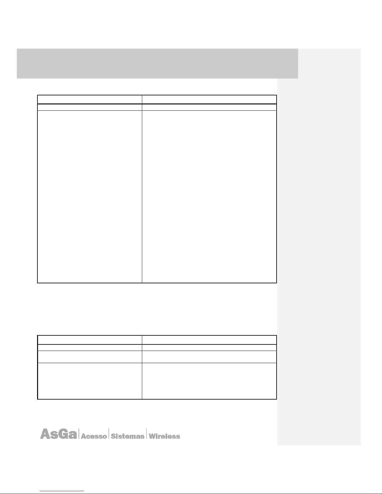
AsGa Light
AsGa LightAsGa Light
AsGa LightBBBBolt 10GigE Switch
olt 10GigE Switcholt 10GigE Switch
olt 10GigE Switch
UUUUser Guide
ser Guideser Guide
ser Guide Configuration
ConfigurationConfiguration
Configuration
41
Extended ACLs specifying the source and Destination ports for TCP/UDP sessions.
COMMAND DESCRIPTION
AsGOS#
configure terminal
Enter the Configure mode
AsGOS(config)# access-list
<extended
access-list-number>
(deny|permit|remark) (tcp|udp)
(A.B.C.D A.B.C.D | any | host
A.B.C.D)
(A.B.C.D A.B.C.D |any | host
A.B.C.D)
Src (eq|gt|lt|neq) PORT dst
(eq|gt|lt|neq) PORT
Define a
extended IP
access number
Deny: Specify packets to reject
permit: Specify packets to forward
Remark: Access list entry comment
tcp:Transmission Control Protocol
udp: User Datagram Protocol
A.B.C.D: Source address
A.B.C.D: Source wildcard bits
any: Any source host
host: A single source host
A.B.C.D: Source address
A.B.C.D: Destination address
A.B.C.D: Destination wildcard bits
Any: Any destination host
host: A single destination host
A.B.C.D: Destination address
Src: Source (TCP/UDP) port
eq: Equal
gt: Greater than
lt: Less than
neq: Not equal
PORT: Port number <0-65535>
dst: Destination (TCP/UDP) port
eq: Equal
gt: Greater than
lt: Less than
neq: Not equal
PORT: Port number <0-65535>
For a complete syntax of access list please refer the alphabetic session.
3.18.5 Istaling IP based Access List
In order to control access to an interface, use the ip access-group command in interface
configuration mode. To remove the specified access group, use the <no> statement of this command.
COMMAND DESCRIPTION
AsGOS#
configure terminal
Enter in the Configuration mode
AsGOS (config)#
interface <IF-
NAME>
Enter into Interface configuration mode.enter a Valid
Interface ID.
AsGOS(config
-
if)#
ip access-
group <ACL-Number> (in|out)
I
p
Interface Internet Protocol config commands
access-group Specify access control for packets
ACL-number IP access list number (Standard or
Extended)
in This ACL is intaled for inbound packets
Out This ACL is installed for outbound packets
Note: In AsGOS ACLs can be installed on an inoterface as in; out or both.

AsGa Light
AsGa LightAsGa Light
AsGa LightBBBBolt 10GigE Switch
olt 10GigE Switcholt 10GigE Switch
olt 10GigE Switch
UUUUser Guide
ser Guideser Guide
ser Guide Configuration
ConfigurationConfiguration
Configuration
42
3.18.6 Configuring MAC Bases Access List
COMMAND DESCRIPTION
AsGOS#
configure terminal
Enter the Configure mode
AsGOS (config)#
access-list
<MAC-ACeess-List Number>
(deny|permit) <MAC ; MAC-MASK |
any > <MAC; MAC-MASK | any;>
deny
Specify packets to reject
permit Specify packets to permit
MAC Source host's MAC address in
HHHH.HHHH.HHHH format
any Source any
MASK Source mask in HHHH.HHHH.HHHH format
MAC Destination host's MAC address in
HHHH.HHHH.HHHH formatce
any Destination any
MASK
Destintion mask in HHHH.HHHH.HHHH format
3.18.7 Istaling MAC based Access List
COMMAND DESCRIPTION
AsGOS#
configure terminal
Enter in the Configure mode
AsGOS (config)#
interface <IFNAME>
Enter into Interface configuration mode.enter a Valid
Interface ID.
AsGOS(config
-
if)#
mac access-
group <ACL-Number> (in)
Mac
config commands
access-group Specify access control for packets
ACL-number IP access list number (Standard or
Extended)
in This ACL is instaled for inbound packets
Note: MAC access Lis can not be instales as OUT into a Interface context.
3.18.8 Aplaying multiple entries to an ACL
Access list can be generated with multiple entries. Assuming the following rules:
access-list 100 deny ip any any
access-list 100 permit ip any host 10.10.10.10
In this case; the last statement has the bigger priority. All paquets with destination IP address
that match with 10.10.10.10 will be switched.
access-list deny ip host 10.10.10.10 any
access-list deny tcp any any dst eq 80
access-list permit ip any host 20.20.20.20
In this case a packet with src-ip 10.10.10.10 dst-ip 20.20.20.20 tcp port 80 will be not bloqued,
because all statement have a “match” for this packet but the last one permit it, the entrie with big
priority.
3.19 Denial of service attack prevention (DoS Prevention)
LightBolt family of switches have a hardware base built in mechanisms in order to detect and
refuse some of the most common DoS attacks. The following lines can be used to little understanding
some of the most common attacks and explain the settings to prevent those attacks.
Denial of service definition: It is an attempt to make a computer resource unavailable to its
intended users.
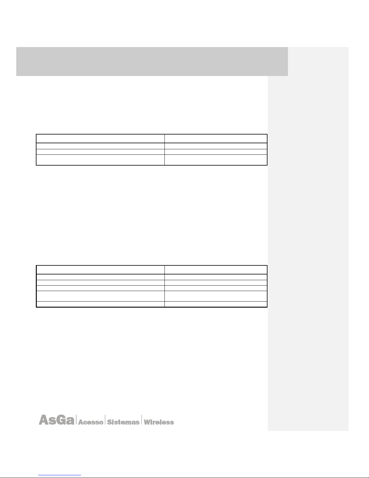
AsGa Light
AsGa LightAsGa Light
AsGa LightBBBBolt 10GigE Switch
olt 10GigE Switcholt 10GigE Switch
olt 10GigE Switch
UUUUser Guide
ser Guideser Guide
ser Guide Configuration
ConfigurationConfiguration
Configuration
43
3.19.1 IP packet with invalid “First-fragment”
A type of attack involving fragments is known as the “tiny fragment attack”. Two TCP fragments
are created. The first fragment is so small that it does not even include the full TCP header,
particularly the destination port number. The second fragment contains the reminder of the TCP
header, including the port number. Some firewalls and intrusion detection systems may let one or
both fragments pass through, particularly if they do not perform packet reassembly. Under this setting
if the first fragment of the packet does not have a full TCP header length the packet will be dropped.
COMMAND DESCRIPTION
AsGOS# configure terminal
Enter in the Configure mode.
AsGOS(config)#
denial-of-service
Enter into Dos mode
configuration
AsGOS(config-dos)# first-fragment-ip-
packets
enable
Enable the first fragment DoS Checking.
All packets detected under those conditions will be discarded.
3.19.2 Fragmented ICMP packets- icmp-attack-check
This type of attack sends the victim's computer series of highly fragmented, oversized ICMP
data packets over the connection. The computer receiving the data packets locks when it tries to put
the fragments together.
If the TCP/IP stack was not built properly, when it tries to keep track and put together several
packets, the result is a memory overflow, which in turn causes the machine to stop responding.
Usually, the attacker only needs to send few packets, locking the victim's computer instantaneously.
When the victim restarts the computer, the connection with the attacker is lost and the attacker
remains anonymous.
Under this setting the system will check for highly ICMP fragmented packet and ICMP Ping
Packets with payloads mayors than those specified by “minimun-icmp-packet-over-size”. Default
value 256.
COMMAND DESCRIPTION
AsGOS# configure terminal
Enter the Configure mode.
AsGOS(config)#
denial-of-service
Enter into Dos mode configuration.
AsGOS(config-dos)# icmp-attack-check enable
Enable ICMP DoS attack checking.
AsGOS(config-dos)# minimun-icmp-packet-oversize 512
Modify the minimum packet oversize ICMP
packet size.
AsGOS(config
-
dos)#
end
All packets detected under those conditions will be discarded.
3.19.3 TCP fragment attack
The attack consists of requesting a TCP connection fragmented into two IP packets. The first IP
packet of 68 bytes only holds the 8 first bytes of the TCP header (source and destination ports and
sequence number). The data in the second IP packet then holds the TCP connection request (SYN
flag is 1 and ACK flag is 0).
However, IP filters apply the same rule to all the fragments in a packet. The filter of the first
fragment (Fragment Offset = 0) defines the rule, accordingly it applies to the other fragments
(Fragment Offset = 1) without any other type of control. So, when defragmenting at IP level on the
target machine, the connection request packet is rebuilt and passed to the TCP layer. The connection
is established despite the IP filter in between which should have prevented it.
Under this setting the system will check for highly TCP fragmented packet and with payloads minors
than those specified by “minimun-tcp-header-allowed”. Default value 20.

AsGa Light
AsGa LightAsGa Light
AsGa LightBBBBolt 10GigE Switch
olt 10GigE Switcholt 10GigE Switch
olt 10GigE Switch
UUUUser Guide
ser Guideser Guide
ser Guide Configuration
ConfigurationConfiguration
Configuration
44
COMMAND DESCRIPTION
AsGOS# configure terminal
Enter
in
the Configure mode.
AsGOS(config)#
denial-of-service
Enter into Dos mode configuration.
AsGOS(config
-
dos)#
tcp-fragment-attack enable
Enable TCP fragment protection
.
AsGOS(config-dos)# minimun-tcp-header-allowed 20
Modify the minimum TCP header allowed
.
AsGOS(config
-
dos)#
end
All packets detected under those conditions will be discarded.
3.19.4 Source IP equal to destination IP attack
This type of attack named LAND attack involves IP packets where the source and destination
address are set to address the same device. The attack involves sending a spoofed TCP SYN packet
(connection initiation) with the target host's IP address and an open port as both source and
destination. The reason a LAND attack works is because it causes the machine to reply to itself
continuously.
UDP/TCP packets where destination ports is the same as source ports are also
considered land type attacks.
Under this setting the system will check for SIP equal to DIP and UDP and TCP source and
destination equals ports.
COMMAND DESCRIPTION
AsGOS# configure terminal
Enter the Configure mode.
AsGOS(config)#
denial-of-service
Enter into Dos mode configuration.
AsGOS(config-dos)# sip-dip-protection enable
SAIP = DAIP checking.
AsGOS(config-dos)# tcp-udp-sp-equal-dp enable
Source and Destination TCP/UDP checking.
AsGOS(co
nfig-dos)#
end
All packets detected under those conditions will be discarded.
3.19.5 Check on invalid TCP flags
TCP is an abbreviation for the Transmission Control Protocol, defined in RFC 793 which was
released in September of 1981. TCP is a connection oriented protocol that can reliably get information
from one host to another across a network. By reliable, we mean that TCP guarantees that all data
will arrive uncorrupted at the remote host, automatically detecting dropped or corrupted packets and
resending them as needed.
Every TCP packet includes a header, which is defined by the RFC as follows:
0 1 2 3
0 1 2 3 4 5 6 7 8 9 0 1 2 3 4 5 6 7 8 9 0 1 2 3 4 5 6 7 8 9 0 1
+-+-+-+-+-+-+-+-+-+-+-+-+-+-+-+-+-+-+-+-+-+-+-+-+-+-+-+-+-+-+-+-+
| Source Port | Destination Port |
+-+-+-+-+-+-+-+-+-+-+-+-+-+-+-+-+-+-+-+-+-+-+-+-+-+-+-+-+-+-+-+-+
| Sequence Number |
+-+-+-+-+-+-+-+-+-+-+-+-+-+-+-+-+-+-+-+-+-+-+-+-+-+-+-+-+-+-+-+-+
| Acknowledgment Number |
+-+-+-+-+-+-+-+-+-+-+-+-+-+-+-+-+-+-+-+-+-+-+-+-+-+-+-+-+-+-+-+-+
| Data | |U|A|P|R|S|F| |
| Offset| Reserved |R|C|S|S|Y|I| Window |
| | |G|K|H|T|N|N| |
+-+-+-+-+-+-+-+-+-+-+-+-+-+-+-+-+-+-+-+-+-+-+-+-+-+-+-+-+-+-+-+-+
| Checksum | Urgent Pointer |
+-+-+-+-+-+-+-+-+-+-+-+-+-+-+-+-+-+-+-+-+-+-+-+-+-+-+-+-+-+-+-+-+
| Options | Padding |
+-+-+-+-+-+-+-+-+-+-+-+-+-+-+-+-+-+-+-+-+-+-+-+-+-+-+-+-+-+-+-+-+
| data |
+-+-+-+-+-+-+-+-+-+-+-+-+-+-+-+-+-+-+-+-+-+-+-+-+-+-+-+-+-+-+-+-+

AsGa Light
AsGa LightAsGa Light
AsGa LightBBBBolt 10GigE Switch
olt 10GigE Switcholt 10GigE Switch
olt 10GigE Switch
UUUUser Guide
ser Guideser Guide
ser Guide Configuration
ConfigurationConfiguration
Configuration
45
Programs utilize TCP by passing it buffers of data. TCP breaks this data into packages known
as segments, and then uses IP to further package these segments into datagrams. Finally, the
datagrams are embedded into a network packet which can be routed across a network.
When the packet arrives at its destination, the IP stack on the remote host extracts the
datagram from the packet, then the segment from the datagram. The segment is then passed up to
the TCP stack, where it can be validated. Ultimately the TCP stack can reassemble all the segments
into the complete buffer which is then passed to the application. TCP provides two way
communication, so this same process occurs in both directions.
Inside of the packet there are some bits related with control structures. Particularly there are six
'control bits' defined in TCP, one or more of which is defined in each packet. The control bits are
'SYN', 'ACK', 'PSH', 'URG', 'RST', and 'FIN'. TCP uses these bits to define the purpose and contents
of a packet. We will briefly define them.
• URG means out of band data. For example in the telnet session if you press ctr-c tcp stack will
send a packet, which has this flag set.
• SYN bit has meaning only when establishing connection e.g. in the handshaking procedure.
Both sides of the connection need to send this special packet with SYN flag on.
• When the ACK flag is on the Acknowledgement field in the tcp packet contains the number of
the next acknowledgeable tcp packet with this sequence number. This bit is on almost in every
packet. ACK flag tells to the target machine that the sending machine has approved all
packets with sequence number below the Ack number in the packet.
• If the reset flag (RST) is on then the connection is destroyed and all data structures in memory
for the connection must be freed.
• With interactive connections PSH (push) flag is used to gain rapid and smooth interaction. The
packet is not queued but rather sent as soon as possible. Interactive programs should thus
use this flag.
• FIN flag tells to the target machine that it should not take anymore data packets from the
sending machine. E.g. the sending machine tells that it wount send anymore packets but can
still receive packets by himself.
AsGa LightBolt Switches have a hardware based built in mechanism to detect malicious control
flag bit combinations. The detected combinations are:
• TCP SYN FLAG = 1 and Source Port < 1024.
• TCP Control Flags =0 and sequence number 0.
• TCP FIN, PUSH, URG bit set and sequence =0.
• TCP SYN, FIN sets.
Under this setting the system will check for those malicious combinations.
COMMAND DESCRIPTION
AsGOS# configure terminal
Enter in the
Configure
mode.
AsGOS(config)#
denial-of-service
Enter into Dos mode configuration.
AsGOS(config
-
dos)#
tcp-on-invalid-
flags enable
Enable the TCP invalid Flag checking.
3.20 Spanning Tree Protocols.
3.20.1 Common Spanning Tree Protocol Commands
All commands in this chapter can be used in the Spanning Tree Protocol (STP), Rapid
Spanning Tree Protocol (RSTP) and Multiple Spanning Tree Protocol (MSTP) daemons.

AsGa Light
AsGa LightAsGa Light
AsGa LightBBBBolt 10GigE Switch
olt 10GigE Switcholt 10GigE Switch
olt 10GigE Switch
UUUUser Guide
ser Guideser Guide
ser Guide Configuration
ConfigurationConfiguration
Configuration
46
3.20.1.1 bridge forward-time
Use this command to set the time (in seconds) after which (if this bridge is the root bridge) each
port changes states to learning and forwarding. This value is used by all instances. To restore the
default value of 15 seconds, use the <no> statement with this command.
Command Syntax
bridge forward-time FORWARD_DELAY
no bridge forward-time
FORWARD_DELAY = <4-30> the forwarding time delay in seconds.
Command Mode
Configure mode
Default
The default value is 15 seconds.
Usage
The allowable range for forward-time is 4-30 seconds. Care should be exercised if the value is to be
made below 7 seconds.
Examples
AsGOS# configure terminal
AsGOS(config)# bridge forward-time 6
Related Commands
bridge protocol ieee
3.20.1.2 bridge hello-time
Use this command to set the hello-time, the time in seconds after which (if this bridge is the root
bridge) all the bridges in a bridged LAN exchange Bridge Protocol Data Units (BPDUs). A very low
value of this parameter leads to excessive traffic on the network, while a higher value delays the
detection of topology change. This value is used by all instances. To restore the default value of the
hello time, use the <no> parameter.
Command Syntax
bridge hello-time HELLOTIME
no bridge hello-time
HELLOTIME = <1-10> The hello BPDU interval in seconds.
Default
Default value is 2 seconds.

AsGa Light
AsGa LightAsGa Light
AsGa LightBBBBolt 10GigE Switch
olt 10GigE Switcholt 10GigE Switch
olt 10GigE Switch
UUUUser Guide
ser Guideser Guide
ser Guide Configuration
ConfigurationConfiguration
Configuration
47
Command Mode
Configure mode
Usage
Configure the bridge instance NAME before using this command. The allowable range of values is 110 seconds. However, make sure that the value of hello time is always greater than the value of hold
time (1 second by default).
Examples
AsGOS# configure terminal
AsGOS(config)# bridge hello-time 3
3.20.1.3 bridge max-age
Use this command to set the max-age for a bridge. This value is used by all instances. Use the
<no> statement with this command to restore the default value of max-age.
Command Syntax
bridge max-age MAXAGE
no bridge max-age
MAXAGE = <6-40> The maximum time, in seconds, to listen for the root
bridge.
Command Mode
Configure mode
Default
The default value of bridge max-age is 20 seconds.
Usage
Max-age is the maximum time in seconds for which (if a bridge is the root bridge) a message is
considered valid. This prevents the frames from looping indefinitely.
The value of max-age should be greater than twice the value of hello time plus one, but less than
twice the value of forward delay minus one. The allowable range for max-age is 6-40 seconds.
Configure this value sufficiently high, so that a frame generated by root can be propagated to the lead
nodes without exceeding the max-age.
Examples
AsGOS# configure terminal
AsGOS(config)# bridge max-age 12
3.20.1.4 bridge priority
Use this command to set bridge priority for the common instance. Using a lower priority
indicates a greater likelihood of the bridge becoming root.

AsGa Light
AsGa LightAsGa Light
AsGa LightBBBBolt 10GigE Switch
olt 10GigE Switcholt 10GigE Switch
olt 10GigE Switch
UUUUser Guide
ser Guideser Guide
ser Guide Configuration
ConfigurationConfiguration
Configuration
48
Command Syntax
bridge priority PRIORITY
PRIORITY = <0-61440> The bridge priority.
Command Mode
Configure mode
Default
The default priority is 32678 (or hex 0x8000).
Usage
This command must be used to set the priority of the bridge. The priority values can be set only in
increments of 4094.
Examples
AsGOS# configure terminal
AsGOS(config)# bridge priority 200
3.20.1.5 bridge spanning-tree errdisable-timeout enable
Use this command to enable the errdisable-timeout facility, which sets a timeout for ports that
are disabled due to the BPDU guard feature.
Command Syntax
bridge spanning-tree errdisable-timeout enable
Default
By default, the port is enabled after 300 seconds.
Command Mode
Configure mode
Usage
The BPDU guard feature shuts down the port on receiving a BPDU on a BPDU-guard enabled port.
This command associates a timer with the feature such that the port gets enabled back without
manual intervention after a set interval.
This interval can be configured by the user using the bridge spanning-tree errdisable-
timeout interval command.
Example
AsGOS# configure terminal
AsGOS(config)# bridge spanning-tree errdisable-timeout enable

AsGa Light
AsGa LightAsGa Light
AsGa LightBBBBolt 10GigE Switch
olt 10GigE Switcholt 10GigE Switch
olt 10GigE Switch
UUUUser Guide
ser Guideser Guide
ser Guide Configuration
ConfigurationConfiguration
Configuration
49
3.20.1.6 bridge spanning-tree errdisable-timeout interval
Use this command to specify the time interval after which a port is brought back up.
Command Syntax
bridge spanning-tree errdisable-timeout interval <10-1000000>
<10-1000000> Specify the errdisable-timeout interval in seconds.
Default
By default, the port is enabled after 300 seconds.
Command Mode
Configure mode
Example
AsGOS# configure terminal
AsGOS(config)# bridge 4 spanning-tree errdisable-timeout interval 34
3.20.1.7 bridge spanning-tree portfast bpdu-filter
Use this command to set portfast BPDU filter for the bridge. All ports that have their BPDU filter
set to default take the same value of bpdu-filter as that of bridge. Use the <no> statement with this
command to disabled the BPDU filter for the bridge.
Command Syntax
(no) bridge spanning-tree portfast bpdu-filter
Command Mode
Configure mode
Usage
The Spanning Tree Protocol sends BPDUs from all ports. Enabling the BPDU Filter feature ensures
that PortFastenabled ports do not transmit or receive any BPDUs. Use the show spanning tree
command to display administratively configured and currently running values of the bpdu-filter
parameter for bridge and port.
Example
AsGOS# configure terminal
AsGOS(config)# bridge spanning-tree portfast bpdu-filter
Related Commands
spanning-tree portfast bpdu-filter

AsGa Light
AsGa LightAsGa Light
AsGa LightBBBBolt 10GigE Switch
olt 10GigE Switcholt 10GigE Switch
olt 10GigE Switch
UUUUser Guide
ser Guideser Guide
ser Guide Configuration
ConfigurationConfiguration
Configuration
50
3.20.1.8 bridge spanning-tree portfast bpdu-guard
Use this command to enable the BPDU (Bridge Protocol Data Unit) Guard feature on a bridge. Use
the <no> statement with this command to disable the BPDU Guard feature on a bridge.
Command Syntax
(no) bridge spanning-tree portfast bpdu-guard
Command Mode
Configure mode
Usage
When the BPDU Guard feature is set for a bridge, all portfast-enabled ports of the bridge that have
bpdu-guard set to default shut down the port on receiving a BPDU. In this case, the BPDU is not
processed. You can either bring the port back up manually by using the no shutdown command, or
configure the errdisable-timeout feature to enable the port after the specified time interval.
Use the <show spanning-tree> command to display the bridge and port configurations for the
BPDU Guard feature. It shows both the administratively configured and currently running values of
bpdu-guard.
Example
AsGOS# configure terminal
AsGOS(config)# bridge spanning-tree portfast bpdu-guard
Related Commands
spanning-tree portfast bpdu-guard, show spanning-tree
3.20.1.9 bridge-group path-cost
Use this command to set the cost of a path associated with a bridge-group. The lower the path
cost, the greater the likelihood of the bridge becoming root.
Command Syntax
bridge-group path-cost PATHCOST
no bridge-group path-cost
PATHCOST = <1-200000000>
The cost to be assigned to the group.
Default
The default bridge-group path cost is 0.
Command Mode
Interface mode

AsGa Light
AsGa LightAsGa Light
AsGa LightBBBBolt 10GigE Switch
olt 10GigE Switcholt 10GigE Switch
olt 10GigE Switch
UUUUser Guide
ser Guideser Guide
ser Guide Configuration
ConfigurationConfiguration
Configuration
51
Examples
AsGOS# configure terminal
AsGOS(config)# interface eth1
AsGOS(config-if)# bridge-group path-cost 123
3.20.1.10 bridge-group priority
Use this command to set the port priority for a bridge. The lower priority indicates a greater
likelihood of the bridge becoming root.
Command Syntax
bridge-group priority PRIORITY
PRIORITY = <0-240> The priority to be assigned to the group.
Default
The default priority is 1.
Command Mode
Interface mode.
Examples
AsGOS# configure terminal
AsGOS(config)# interface eth1
AsGOS(config-if)# bridge-group 4 priority 100
3.20.1.11 spanning-tree guard root
Use this command to enable the Root Guard feature for the port. The root guard feature
disables reception of superior BPDUs. Use the <no> statement with this command to disable the root
guard feature for the port.
Command Syntax
(no)spanning-tree guard root
Command Mode
Interface mode
Usage
The Root Guard feature makes sure that the port on which it is enabled is a designated port. If the
Root Guard enabled port receives a superior BPDU, it goes to a Listening state (for STP) or
discarding state (for RSTP and MSTP).
Example
AsGOS# configure terminal
AsGOS(config)# interface ge0

AsGa Light
AsGa LightAsGa Light
AsGa LightBBBBolt 10GigE Switch
olt 10GigE Switcholt 10GigE Switch
olt 10GigE Switch
UUUUser Guide
ser Guideser Guide
ser Guide Configuration
ConfigurationConfiguration
Configuration
52
AsGOS(config-if)# spanning-tree guard root
3.20.2 STP Commands
This chapter lists the commands that are exclusive to the Spanning Tree Protocol (STP). For
other commands useful in the Spanning Tree Protocol, see the Common Spanning Tree Protocol
Commands chapter.
3.20.2.1 bridge shutdown
Use the <bridge shutdown> command to disable a bridge, and <no bridge shutdown> to reset
the bridge.
Command Syntax
bridge shutdown
no bridge shutdown
Command Mode
Configure mode
Usage
Make sure to use the <bridge instance NAME> command before using this command.
Examples
AsGOS# configure terminal
AsGOS(config)# bridge shutdown 4
Related Commands
bridge instance
3.20.2.2 bridge spanning-tree enable
Use this command to enable the Spanning Tree Protocol on a bridge. Use the <no> statement
to disable the Spanning Tree Protocol on the bridge.
Command Syntax
(no) bridge spanning-tree enable
Command Mode
Configure mode
Default
There is no default value.

AsGa Light
AsGa LightAsGa Light
AsGa LightBBBBolt 10GigE Switch
olt 10GigE Switcholt 10GigE Switch
olt 10GigE Switch
UUUUser Guide
ser Guideser Guide
ser Guide Configuration
ConfigurationConfiguration
Configuration
53
Example
AsGOS# configure terminal
AsGOS(config)# bridge 2 spanning-tree enable
3.20.2.3 debug stp
Use this command to turn on, and turn off, debugging and echoing data to the console, at
various levels. Use the <no> statement with this command to turn off debugging.
Command Syntax
debug stp (all|cli|event|PACKET|protocol|timer)
all echoes all STP debugging levels to the console.
cli echoes STP commands to the console.
event echoes events to console.
PACKET = packet rx|tx echoes STP packets to the console.
rx received packets.
tx transmitted packets.
protocol echoes protocol changes to the console.
timer echoes timer start to the console.
Command Mode
Configure mode
Examples
AsGOS# configure terminal
AsGOS(config)# debug stp all
AsGOS(config)# debug stp cli
AsGOS(config)# debug stp packet rx
AsGOS(config)# debug stp protocol detail
AsGOS(config)# debug stp timer
3.20.2.4 show spanning-tree
This command shows the state of the spanning tree for all named bridge groups. To modify the
lines displayed, use the | (output modifier token); to save the output to a file, use the > (output
redirection token). For more information, see AsGOS Command Line Interface Environment.
Command Syntax
show spanning-tree
Command Mode
Privileged Exec, Configure and Interface modes.
Examples
AsGOS# show spanning-tree

AsGa Light
AsGa LightAsGa Light
AsGa LightBBBBolt 10GigE Switch
olt 10GigE Switcholt 10GigE Switch
olt 10GigE Switch
UUUUser Guide
ser Guideser Guide
ser Guide Configuration
ConfigurationConfiguration
Configuration
54
Usage
The following is an output of this command displaying the spanning tree.
AsGOS# show spanning-tree
% a: spanning tree enabled - learning enabled
% a: ageing-time 300 - root path cost 0 - priority 40
% a: forward-time 15 - hello-time 2 - max-age 20 - root port 0
% a: root id 0000000475e650cf
% a: bridge id 0000000475e650cf
% a: hello timer 0 - tcn timer 0 - topo change timer 0
% a: 1 topology changes - last topology change Tue Dec 16 23:05:33 2003
% eth3: port 5 - id 8005 - path cost 20000000 - designated cost 0
% eth3: designated port id 8005 - state Forwarding - priority 128
% eth3: designated root 0000000475e650cf
% eth3: designated bridge 0000000475e650cf
% eth3: forward-timer 0 - hold-timer 0 - msg age timer 0
% eth3: forward-transitions 2
% eth2: port 4 - id 8004 - path cost 20000000 - designated cost 0
% eth2: designated port id 8004 - state Forwarding - priority 128
% eth2: designated root 0000000475e650cf
% eth2: designated bridge 0000000475e650cf
% eth2: forward-timer 0 - hold-timer 0 - msg age timer 0
% eth2: forward-transitions 1
3.20.3 RSTP Commands
This chapter lists the commands that are exclusive to the Rapid Spanning Tree Protocol. For
other commands useful in the RSTP, see the Common Spanning Tree Protocol Commands chapter.
3.20.3.1 bridge rapid-spanning-tree enable
Use this command to enable the Rapid Spanning Tree Protocol on a bridge. Use the <no>
statement to disable the Rapid Spanning Tree Protocol on the bridge.
Command Syntax
<no> bridge rapid-spanning-tree enable
Bridge-group ID used for bridging.
Command Mode
Configure mode
Default
There is no default value.
Examples
AsGOS# configure terminal
AsGOS(config)# bridge rapid-spanning-tree enable

AsGa Light
AsGa LightAsGa Light
AsGa LightBBBBolt 10GigE Switch
olt 10GigE Switcholt 10GigE Switch
olt 10GigE Switch
UUUUser Guide
ser Guideser Guide
ser Guide Configuration
ConfigurationConfiguration
Configuration
55
3.20.3.2 bridge shutdown
Use this command to reset a bridge. Use the <bridge shutdown> command to disable a
bridge, and <no bridge shutdown> to return the bridge to operation.
Command Syntax
bridge shutdown
no bridge shutdown
Bridge-group ID used for bridging.
Command Mode
Configure mode
Usage
The bridge instance NAME must exist prior to using this command.
Examples
AsGOS# configure terminal
AsGOS(config)# bridge shutdown
3.20.3.3 clear spanning-tree detected protocols
Use this command to clear the detected protocols for a specific bridge or interface.
Command Syntax
clear spanning-tree detected protocols [bridge]|[interface IFNAME]
IFNAME Specify the name of the interface on which protocols have to be
cleared.
Command Mode
Privileged Exec mode
Example
AsGOS# clear spanning-tree detected protocols bridge
3.20.3.4 debug rstp
Use this command to turn on, and turn off, debugging and echoing data to the console, at
various levels. Use the no parameter with this command to turn off debugging.
Command Syntax
debug rstp (all|cli|PACKET|PROTOCOL|TIMER)
all echoes all RSTP debugging levels to the console.
cli echoes RSTP commands to the console.
PACKET = packet rx|tx echoes RSTP packets to the console.
rx received packets.

AsGa Light
AsGa LightAsGa Light
AsGa LightBBBBolt 10GigE Switch
olt 10GigE Switcholt 10GigE Switch
olt 10GigE Switch
UUUUser Guide
ser Guideser Guide
ser Guide Configuration
ConfigurationConfiguration
Configuration
56
tx transmitted packets.
PROTOCOL = protocol (detail) echoes protocol changes to the console.
TIMER = timer (detail) echoes timer start to the console.
detail displays detailed output.
Command Mode
Configure mode
Examples
AsGOS# configure terminal
AsGOS(config)# debug rstp all
AsGOS(config)# debug rstp cli
AsGOS(config)# debug rstp packet rx
AsGOS(config)# debug rstp protocol detail
AsGOS(config)# debug rstp timer
3.20.3.5 show spanning-tree
This command shows the state of the spanning tree for all named bridge-groups. To modify the
lines displayed, use the | (output modifier token); to save the output to a file, use the > (output
redirection token).
Command Syntax
show spanning-tree
Command Mode
Privileged Exec, Configure and Interface modes.
Examples
AsGOS# show spanning-tree
Usage
The following is an output of this command displaying the state of the spanning tree.
AsGOS# show spanning-tree
% a: spanning tree enabled - learning enabled
% a: ageing-time 300 - root path cost 0 - priority 40
% a: forward-time 15 - hello-time 2 - max-age 20 - root port 0
% a: root id 0000000475e650cf
% a: bridge id 0000000475e650cf
% a: hello timer 0 - tcn timer 0 - topo change timer 0
% a: 1 topology changes - last topology change Tue Dec 16 23:05:33 2003
% eth3: port 5 - id 8005 - path cost 20000000 - designated cost 0
% eth3: designated port id 8005 - state Forwarding - priority 128
% eth3: designated root 0000000475e650cf
% eth3: designated bridge 0000000475e650cf
% eth3: forward-timer 0 - hold-timer 0 - msg age timer 0
% eth3: forward-transitions 2
% eth2: port 4 - id 8004 - path cost 20000000 - designated cost 0
% eth2: designated port id 8004 - state Forwarding - priority 128
% eth2: designated root 0000000475e650cf

AsGa Light
AsGa LightAsGa Light
AsGa LightBBBBolt 10GigE Switch
olt 10GigE Switcholt 10GigE Switch
olt 10GigE Switch
UUUUser Guide
ser Guideser Guide
ser Guide Configuration
ConfigurationConfiguration
Configuration
57
% eth2: designated bridge 0000000475e650cf
% eth2: forward-timer 0 - hold-timer 0 - msg age timer 0
% eth2: forward-transitions 1
3.20.3.6 spanning-tree force-version
Use this command to specify the version. A version identifier of less than a value of 2 enforces
the spanning tree protocol. Although the command supports an input range of 0-3, for RSTP, the valid
range is 0-2. Use the no parameter with this command to set the default protocol version.
Command Syntax
(no) spanning-tree force-version VERSION
VERSION <0-3> Version identifier. (0 - STP, 1- Not supported, 2 - RSTP, 3 - MSTP)
Command Mode
Interface mode
Examples
Set the value to enforce the spanning tree protocol:
AsGOS# configure terminal
AsGOS(config)# interface eth0
AsGOS(config-if)# spanning-tree force-version 1
Set the default protocol version:
AsGOS# configure terminal
AsGOS(config)# interface eth0
AsGOS(config-if)# no spanning-tree force-version
3.20.3.7 spanning-tree link-type
Use this command to enable or disable point-to-point or shared link types. Use the <no>
statement with this command to disable rapid transition.
Command Syntax
(no) spanning-tree link-type point-to-point
(no) spanning-tree link-type shared
shared: Disable rapid transition.
point-to-point: Enable rapid transition.
Command Mode
Interface mode
Usage
RSTP has a backward-compatible STP mode, spanning-tree link-type shared. An
alternative is the spanning-tree force-version 0.

AsGa Light
AsGa LightAsGa Light
AsGa LightBBBBolt 10GigE Switch
olt 10GigE Switcholt 10GigE Switch
olt 10GigE Switch
UUUUser Guide
ser Guideser Guide
ser Guide Configuration
ConfigurationConfiguration
Configuration
58
Examples
AsGOS# configure terminal
AsGOS(config)# interface eth0
AsGOS(config-if)# spanning-tree link-type point-to-point
3.20.4 MSTP Commands
This chapter lists the commands that are exclusive to the Multiple Spanning Tree Protocol
(MSTP). For other commands useful in the MSTP, see the Common Spanning Tree Protocol
Commands chapter.
3.20.4.1 bridge cisco-interoperability
Use this command to enable/disable Cisco interoperability for MSTP.
Command Syntax
bridge cisco-interoperability (enable | disable)
enable: Enable Cisco interoperability for MSTP bridge.
Disable: Disable Cisco interoperability for MSTP bridge
Default
If this command is not used, Cisco interoperability is disabled.
Command Mode
Configure mode
Usage
If Cisco interoperability is required, all AsGOS boxes in the switched LAN must be Ciscointeroperability enabled. When AsGOS is interoperating with Cisco, the only criteria used to classify a
region are the region name and revision level.VLAN to instance mapping is not used to classify
regions when interoperating with Cisco.
Examples
To enable Cisco interoperability on a Layer-2 switch for a particular bridge (bridge 2 in this example):
AsGOS# configure terminal
AsGOS(config)# bridge cisco-interoperability enable
To disable Cisco interoperability on a Layer-2 switch for a particular bridge:
AsGOS# configure terminal
AsGOS(config)# bridge cisco-interoperability disable
3.20.4.2 bridge instance priority
Set the bridge priority for an MST instance to the value specified. To restore the default value of
the bridge priority, use the <no> statement with this command.

AsGa Light
AsGa LightAsGa Light
AsGa LightBBBBolt 10GigE Switch
olt 10GigE Switcholt 10GigE Switch
olt 10GigE Switch
UUUUser Guide
ser Guideser Guide
ser Guide Configuration
ConfigurationConfiguration
Configuration
59
Command Syntax
bridge <1-32> instance INSTANCE_ID priority BRIDGE_PRIORITY
no bridge <1-32> instance INSTANCE_ID priority
<1-32> Specify the bridge-group ID.
INSTANCE_ID Specify the instance ID.
BRIDGE_PRIORITY <0-61440> Specify the bridge priority (a lower priority indicates a greater
likelihood of the bridge becoming root).
Command Mode
Configure mode.
Default
The default value of the priority for each instance is 32768.
Usage
The lower the priority of the bridge, the better the chances are of the bridge becoming a root bridge or
a designated bridge for the LAN. The permitted range of values is 0-61440. The priority values can be
set only in increments of 4094.
Examples
AsGOS# configure terminal
AsGOS(config)# bridge 4 instance 3 priority 3
3.20.4.3 bridge instance vlan
Use this command to create an instance of a VLAN. This command can be used only after the
VLAN is defined.
Command Syntax
bridge <1-32> instance INSTANCE_ID vlan VLAN_ID
no bridge <1-32> vlan VLAN_ID
<1-32> Specify the bridge-group ID.
INSTANCE_ID Specify the instance ID.
VLAN_ID <1-4094> Specify a VLAN ID to be associated to the instance.
Command Mode
MST Configuration Mode
Usage
The permitted range of instances is 0-15. Instance 0 refers to the internal spanning tree. The VLANs
must be created before being associated with an MST instance (MSTI). If the VLAN range is not
specified, the MSTI will not be created.
Example
AsGOS# configure terminal

AsGa Light
AsGa LightAsGa Light
AsGa LightBBBBolt 10GigE Switch
olt 10GigE Switcholt 10GigE Switch
olt 10GigE Switch
UUUUser Guide
ser Guideser Guide
ser Guide Configuration
ConfigurationConfiguration
Configuration
60
AsGOS(config)# bridge 2 protocol mstp
AsGOS(config)# spanning-tree mst configuration
AsGOS(config-mst) bridge 2 instance 2 vlan 30
3.20.4.4 bridge max-hops
Use this command to specify the maximum allowed hops for a BPDU in an MST region. This
parameter is used by all the instances of the MST. To restore the default value, use the no parameter
with this command.
Command Syntax
bridge <1-32> max-hops HOP_COUNT
no bridge <1-32> max-hops
<1-32> Specify the bridge-group ID.
HOP_COUNT Maximum hops the BPDU will be valid for.
Command Mode
Configure Mode
Default
The default max-hops in a MST region are 20.
Usage
Specifying the max hops for a BPDU prevents the messages from looping indefinitely in the network.
When a bridge receives a MST BPDU that has exceeded the allowed max-hops, it discards the
BPDU.
Examples
AsGOS# configure terminal
AsGOS(config)# bridge 3 max-hops 25
3.20.4.5 bridge multiple-spanning-tree enable
Use this command to enable the Multiple Spanning Tree Protocol on a bridge. Use the <no>
statement to disable the command.
Command Syntax
(no) bridge <1-32> multiple-spanning-tree enable
<1-32> Specify the bridge-group ID.
Command Mode
Configure mode
Default
There is no default value.

AsGa Light
AsGa LightAsGa Light
AsGa LightBBBBolt 10GigE Switch
olt 10GigE Switcholt 10GigE Switch
olt 10GigE Switch
UUUUser Guide
ser Guideser Guide
ser Guide Configuration
ConfigurationConfiguration
Configuration
61
Example
AsGOS# configure terminal
AsGOS(config)# bridge 2 multiple spanning-tree enable
3.20.4.6 bridge region
Use this command to create an MST region, and specify a name to it. MST bridges of a region
form different spanning trees for different VLANs.
Command Syntax
bridge <1-32> region REGION_NAME
no bridge <1-32> region REGION_NAME
<1-32> Specify the bridge-group ID.
REGION_NAME Specify the name of the region.
Command Mode
MST Configuration mode
Default
By default, each MST bridge starts with the region name as its bridge address. This means each MST
bridge is a region by itself, unless specifically added to one.
Examples
AsGOS# configure terminal
AsGOS(config)# spanning-tree mst configuration
AsGOS(config-mst)# bridge 3 region IPI
3.20.4.7 bridge revision
Use this command to specify the number for configuration information.
Command Syntax
bridge <1-32> revision REVISION_NUM
<1-32> Specify the bridge-group ID.
REVISION_NUM <0-255> Revision number.
Command Mode
MST Configuration Mode
Default
The default value of revision number is 0.
Examples
AsGOS# configure terminal
AsGOS(config)# spanning-tree mst configuration

AsGa Light
AsGa LightAsGa Light
AsGa LightBBBBolt 10GigE Switch
olt 10GigE Switcholt 10GigE Switch
olt 10GigE Switch
UUUUser Guide
ser Guideser Guide
ser Guide Configuration
ConfigurationConfiguration
Configuration
62
AsGOS(config-mst)# bridge 3 revision 25
3.20.4.8 bridge-group instance
Use this command to assign a Multiple Spanning Tree instance to a port. Use the <no>
statement with this command to remove the instance.
Command Syntax
bridge-group <1-32> instance INSTANCE_ID
no bridge-group <1-32> instance
<1-32> Specify the bridge-group number for bridging.
INSTANCE_ID <1-16> Specify the instance ID.
Command Mode
Interface mode
Examples
AsGOS# configure terminal
AsGOS(config)# interface eth0
AsGOS(config-if)# bridge-group 4 instance 3
3.20.4.9 bridge-group instance path-cost
Use this command to set the cost of a path associated with an interface. Use the <no>
statement with this command to restore the default cost value of the path.
Command Syntax
bridge-group <1-32> instance INSTANCE_ID path-cost PATH_COST
no bridge-group <1-32> path-cost
<1-32> Specify the bridge-group number for bridging
PATH_COST <1-200000000> Specify the cost of path in the range of <1-200000000> (a lower path-
cost indicates a greater likelihood of the specific interface becoming a root)
Command Mode
Interface mode
Default
Assuming a 10 Mb/s link speed, the default value is configured as 200,000.
Examples
AsGOS# configure terminal
AsGOS(config)# interface eth0
AsGOS(config-if)# bridge-group 4 instance 3 path-cost 1000

AsGa Light
AsGa LightAsGa Light
AsGa LightBBBBolt 10GigE Switch
olt 10GigE Switcholt 10GigE Switch
olt 10GigE Switch
UUUUser Guide
ser Guideser Guide
ser Guide Configuration
ConfigurationConfiguration
Configuration
63
3.20.4.10 bridge-group instance priority
Use this command to set the port priority for a bridge group. Use the <no> statement with this
command to restore the default priority value.
Command Syntax
bridge-group <1-32> instance INSTANCE_ID priority PRIORITY
no bridge-group <1-32> instance priority INSTANCE_ID
<1-32> Specify the bridge-group number for bridging.
INSTANCE_ID Specify the identifier.
PRIORITY <0-240> Specify the port priority in a range of <0-240> (a lower priority indicates greater
likelihood of the interface becoming a root).
Command Mode
Interface mode
Default
The default value of port priority for each instance is 128.
Usage
The Multiple Spanning Tree Protocol uses port priority as a tiebreaker to determine which port should
forward frames for a particular instance on a LAN, or which port should be the root port for an
instance. A lower value implies a better priority. In the case of the same priority, the interface index
will serve as the tiebreaker, with the lower-numbered interface being preferred over others. The
permitted range is 0-240. The priority values can only be set in increments of 16.
Examples
AsGOS# configure terminal
AsGOS(config)# interface eth0
AsGOS(config-if)# bridge-group 4 instance 3 priority 121
3.20.4.11 clear spanning-tree detected protocols
Use this command to clear the detected protocols for a specific bridge or interface.
Command Syntax
clear spanning-tree detected protocols [bridge <1-32>]|[interface IFNAME]
<1-32> Specify the number of the bridge group on which protocols have to be cleared.
IFNAME Specify the name of the interface on which protocols have to be cleared
Command Mode
Privileged Exec mode
Default
The default value of revision number is 0.

AsGa Light
AsGa LightAsGa Light
AsGa LightBBBBolt 10GigE Switch
olt 10GigE Switcholt 10GigE Switch
olt 10GigE Switch
UUUUser Guide
ser Guideser Guide
ser Guide Configuration
ConfigurationConfiguration
Configuration
64
Examples
AsGOS# clear spanning-tree detected protocols bridge 2
3.20.4.12 debug mstp
Use this command to turn on, and turn off, debugging and echoing data to the console, at
various levels. Use the no parameter with this command, to turn off debugging.
Command Syntax
debug mstp (all|cli|PACKET|PROTOCOL|TIMER)
all echoes all STP debugging levels to the console.
cli echoes STP commands to the console.
PACKET = packet rx|tx echoes MSTP packets to the console.
rx received packets.
tx transmitted packets.
PROTOCOL protocol (detail) echoes protocol changes to the console.
TIMER timer (detail) echoes timer start to the console.
detail detailed output.
Command Mode
Exec, Privileged Exec and Configure modes
Examples
AsGOS# configure terminal
AsGOS(config)# debug mstp all
AsGOS(config)# debug mstp cli
AsGOS(config)# debug mstp packet rx
AsGOS(config)# debug mstp protocol detail
AsGOS(config)# debug mstp timer
3.20.4.13 show spanning-tree mst
Use this command to display the filtering database values. This command displays the number
of instances created, and VLANs associated with it.
Command Syntax
show spanning-tree mst
Command Mode
Enable mode and Interface mode
Usage
The following is a display of this command showing the number of instances created, and the VLANs
associated with it.
AsGOS# show spanning-tree mst
% b: Bridge up - Spanning Tree Enabled
% b: CIST Root Path Cost 0 - CIST Root Port 0 - CIST Bridge Priority 32768
% b: Forward Delay 15 - Hello Time 2 - Max Age 20 - Max-hops 20
% b: CIST Root Id 8000000475e93ffe
% b: CIST Reg Root Id 8000000475e93ffe

AsGa Light
AsGa LightAsGa Light
AsGa LightBBBBolt 10GigE Switch
olt 10GigE Switcholt 10GigE Switch
olt 10GigE Switch
UUUUser Guide
ser Guideser Guide
ser Guide Configuration
ConfigurationConfiguration
Configuration
65
% b: CST Bridge Id 8000000475e93ffe
%
% Instance VLAN
% 0: 1
% 2: 4
3.20.4.14 show spanning-tree mst config
Use this command to display MSTP configuration information for a bridge.
Command Syntax
show spanning-tree mst config
Command Mode
Enable mode and Interface mode
Usage
The following show output displays the MSTP configuration information for bridge b.
AsGOS# show spanning-tree mst config
%
% MSTP Configuration Information for bridge b :
%-----------------------------------------------------% Format Id : 0
% Name : My Name
% Revision Level : 0
% Digest : 0x80DEE46DA92A98CF21C603291B22880A
%------------------------------------------------------
3.20.4.15 show spanning-tree mst detail
Use this command to display the filtering database values. The <show spanning-tree
mst> detail prints the detailed information about each instance, and all interfaces associated with that
particular instance.
Command Syntax
show spanning-tree mst detail
Command Mode
Enable mode and Interface mode
Usage
The following is a display of this command showing displaying detailed information about each
instance, and all interfaces associated with them.
AsGOS# show spanning-tree mst detail
% 1: Bridge up - Spanning Tree Enabled
% 1: CIST Root Path Cost 0 - CIST Root Port 0 - CIST Bridge Priority 0
% 1: Forward Delay 15 - Hello Time 2 - Max Age 20 - Max-hops 20
% 1: CIST Root Id 0000009027342b72
% 1: CIST Reg Root Id 0000009027342b72
% 1: CST Bridge Id 0000009027342b72
% 1: portfast bpdu-filter disabled
% 1: portfast bpdu-guard disabled

AsGa Light
AsGa LightAsGa Light
AsGa LightBBBBolt 10GigE Switch
olt 10GigE Switcholt 10GigE Switch
olt 10GigE Switch
UUUUser Guide
ser Guideser Guide
ser Guide Configuration
ConfigurationConfiguration
Configuration
66
% 1: portfast errdisable timeout disabled
% 1: portfast errdisable timeout interval 1 sec
% eth2: Port 4 - Id 8004 - Role Designated - State Forwarding
% eth2: Designated External Path Cost 0 -Internal Path Cost 0
% eth2: Configured Path Cost 200000 - Add type Explicit ref count 2
% eth2: Designated Port Id 8004 - CST Priority 128 % eth2: CIST Root 0000009027342b72
% eth2: Regional Root 0000009027342b72
% eth2: Designated Bridge 0000009027342b72
% eth2: Message Age 0 - Max Age 20
% eth2: CIST Hello Time 2 - Forward Delay 15
% eth2: CIST Forward Timer 0 - Msg Age Timer 0 - Hello Timer 0
% eth2: Version Multiple Spanning Tree Protocol - Received None - Send STP
% eth2: No portfast configured - Current portfast off
% eth2: portfast bpdu-guard default - Current portfast bpdu-guard off
% eth2: portfast bpdu-filter default - Current portfast bpdu-filter off
% eth2: no root guard configured - Current root guard off
% eth2: Configured Link Type point-to-point - Current point-to-point
%
% eth1: Port 3 - Id 8003 - Role Designated - State Forwarding
% eth1: Designated External Path Cost 0 -Internal Path Cost 0
% eth1: Configured Path Cost 200000 - Add type Explicit ref count 2
% eth1: Designated Port Id 8003 - CST Priority 128 % eth1: CIST Root 0000009027342b72
% eth1: Regional Root 0000009027342b72
% eth1: Designated Bridge 0000009027342b72
% eth1: Message Age 0 - Max Age 20
% eth1: CIST Hello Time 2 - Forward Delay 15
% eth1: CIST Forward Timer 0 - Msg Age Timer 0 - Hello Timer 0
% eth1: Version Multiple Spanning Tree Protocol - Received STP - Send STP
% eth1: No portfast configured - Current portfast off
% eth1: portfast bpdu-guard default - Current portfast bpdu-guard off
% eth1: portfast bpdu-filter default - Current portfast bpdu-filter off
% eth1: no root guard configured - Current root guard off
% eth1: Configured Link Type point-to-point - Current point-to-point
%
% Instance 1: Vlans: 2
% 1: MSTI Root Path Cost 0 - MSTI Root Port 0 - MSTI Bridge Priority 32768
% 1: MSTI Root Id 8001009027342b72
% 1: MSTI Bridge Id 8001009027342b72
% eth2: Port 4 - Id 8004 - Role Designated - State Forwarding
% eth2: Designated Internal Path Cost 0 - Designated Port Id 8004
% eth2: Configured Internal Path Cost 200000
% eth2: Configured CST External Path cost 200000
% eth2: CST Priority 128 - MSTI Priority 128
% eth2: Designated Root 8001009027342b72
% eth2: Designated Bridge 8001009027342b72
% eth2: Message Age 0 - Max Age 0
% eth2: Hello Time 2 - Forward Delay 15
% eth2: Forward Timer 0 - Msg Age Timer 0 - Hello Timer 0
%
% eth1: Port 3 - Id 8003 - Role Designated - State Forwarding
% eth1: Designated Internal Path Cost 0 - Designated Port Id 8003
% eth1: Configured Internal Path Cost 200000
% eth1: Configured CST External Path cost 200000
% eth1: CST Priority 128 - MSTI Priority 128
% eth1: Designated Root 8001009027342b72
% eth1: Designated Bridge 8001009027342b72
% eth1: Message Age 0 - Max Age 0
% eth1: Hello Time 2 - Forward Delay 15
% eth1: Forward Timer 0 - Msg Age Timer 0 - Hello Timer 0
3.20.4.16 show spanning-tree mst instance
The <show spanning-tree mst instance> displays detailed information for the specified
instance, and all interfaces associated with that instance.

AsGa Light
AsGa LightAsGa Light
AsGa LightBBBBolt 10GigE Switch
olt 10GigE Switcholt 10GigE Switch
olt 10GigE Switch
UUUUser Guide
ser Guideser Guide
ser Guide Configuration
ConfigurationConfiguration
Configuration
67
Command Syntax
show spanning-tree mst instance INSTANCE_ID
INSTANCE_ID Specify the instance ID for which information needs to be
displayed.
Command Mode
Enable mode and Interface mode
Usage
The following is a display of this command showing detailed information for instance 2.
AsGOS# show spanning-tree mst instance 2
% 1: Bridge up - Spanning Tree Enabled
% 1: CIST Root Path Cost 0 - CIST Root Port 0 - CIST Bridge Priority 0
% 1: Forward Delay 15 - Hello Time 2 - Max Age 20 - Max-hops 20
% 1: CIST Root Id 0000009027342b72
% 1: CIST Reg Root Id 0000009027342b72
% 1: CST Bridge Id 0000009027342b72
% 1: portfast bpdu-filter disabled
% 1: portfast bpdu-guard disabled
% 1: portfast errdisable timeout disabled
% 1: portfast errdisable timeout interval 1 sec
%
% 1: MSTI Root Path Cost 0 - MSTI Root Port 0 - MSTI Bridge Priority 32768
% 1: MSTI Root Id 8002009027342b72
% 1: MSTI Bridge Id 8002009027342b72
% eth2: Port 4 - Id 8004 - Role Designated - State Discarding
% eth2: Designated Internal Path Cost 0 - Designated Port Id 8004
% eth2: Configured Internal Path Cost 200000
% eth2: Configured CST External Path cost 200000
% eth2: CST Priority 128 - MSTI Priority 128
% eth2: Designated Root 8002009027342b72
% eth2: Designated Bridge 8002009027342b72
% eth2: Message Age 0 - Max Age 0
% eth2: Hello Time 2 - Forward Delay 15
% eth2: Forward Timer 11 - Msg Age Timer 0 - Hello Timer 1
%
% eth1: Port 3 - Id 8003 - Role Designated - State Discarding
% eth1: Designated Internal Path Cost 0 - Designated Port Id 8003
% eth1: Configured Internal Path Cost 200000
% eth1: Configured CST External Path cost 200000
% eth1: CST Priority 128 - MSTI Priority 128
% eth1: Designated Root 8002009027342b72
% eth1: Designated Bridge 8002009027342b72
% eth1: Message Age 0 - Max Age 0
% eth1: Hello Time 2 - Forward Delay 15
% eth1: Forward Timer 7 - Msg Age Timer 0 - Hello Timer 1
3.20.4.17 spanning-tree force-version
Use this command to specify the spanning-tree force (STP) version. A version identifier of less
than a value of 2 enforces the spanning tree protocol. Use the no parameter with this command to set
the default protocol version.
Command Syntax
(no) spanning-tree force-version VERSION
VERSION <0-3> Version identifier. (0 - STP, 1- Not supported, 2 - RSTP, 3 - MSTP)

AsGa Light
AsGa LightAsGa Light
AsGa LightBBBBolt 10GigE Switch
olt 10GigE Switcholt 10GigE Switch
olt 10GigE Switch
UUUUser Guide
ser Guideser Guide
ser Guide Configuration
ConfigurationConfiguration
Configuration
68
Command Mode
Interface mode
Examples
Set the value to enforce the spanning tree protocol:
AsGOS# configure terminal
AsGOS(config)# interface eth0
AsGOS(config-if)# spanning-tree force-version 1
Set the default protocol version:
AsGOS# configure terminal
AsGOS(config)# interface eth0
AsGOS(config-if)# no spanning-tree force-version
3.20.4.18 link-type
Use this command to enable or disable point-to-point or shared link types.
Command Syntax
(no) spanning-tree link-type point-to-point
(no) spanning-tree link-type shared
shared Disable rapid transition.
point-to-point Enable rapid transition.
Command Mode
Interface mode
Usage
MSTP has a backward-compatible STP mode, spanning-tree link-type shared. An
alternative is the spanning-tree force-version 0.
Examples
AsGOS# configure terminal
AsGOS(config)# interface eth0
AsGOS(config-if)# spanning-tree link-type point-to-point
3.20.4.19 spanning-tree mst configuration
Use this command to enter the Multiple Spanning Tree Configuration mode.
Command Syntax
spanning-tree mst configuration
Command Mode
Configure mode

AsGa Light
AsGa LightAsGa Light
AsGa LightBBBBolt 10GigE Switch
olt 10GigE Switcholt 10GigE Switch
olt 10GigE Switch
UUUUser Guide
ser Guideser Guide
ser Guide Configuration
ConfigurationConfiguration
Configuration
69
Examples
AsGOS# configure terminal
AsGOS(config)# spanning-tree mst configuration
AsGOS(config-mst)#
3.21 Link Agregation Control Protocol Commands Set.
Link Aggregation Control Protocol (LACP) is part of an IEEE specification (802.3ad) that allows
to bundle physical ports into a single logical channel. LACP allows a switch to negotiate an automatic
bundle by sending special PDUs named LACP packets to the peer.
Link Aggregation provides several benefits: Increased bandwidth, load balancing, and allows
you to create redundant ethernet links. If a link in a ethernet channel goes down, the switches on
wich is configured to use LACP will automatically fail over to the links that are still up and remain
connected
3.21.1 channel-group
Assign the interface to a channel group, and specify the LACP mode. For channel-groupnumber, the range is 1 to 32. Each Channel can have up to eight compatibly configured Ethernet
interfaces.
When You configure Layer 2 EtherChannels by configuring the Ethernet interfaces with the
channel-group interface configuration command, the system creates the port-channel logical
interface. Each Ethernet Interfaces pertaining to the same LACP Group will heritage port-channel
interface characteristics.
Command Syntax
channel-group [
channel-group-number
] <1-32> mode ( lacp
(active|passive) | static)
For channel-group-number, the range is 1 to 32. Each
For mode, select one of these keywords:
Lacp: Select this port channel as a LACP port channel.
active: Enables LACP only if an LACP device is detected. It places an interface into an active
negotiating state, in which the interface starts negotiations with other interfaces by sending LACP
packets.
passive: Enables LACP on an interface and places it into a passive negotiating state, in which the
interface responds to LACP packets that it receives, but does not start LACP packet negotiation.
Command Mode
Interface mode
Usage
channel-group [ channel-group-number ] <1-32> mode ( lacp (active|passive)
| static)

AsGa Light
AsGa LightAsGa Light
AsGa LightBBBBolt 10GigE Switch
olt 10GigE Switcholt 10GigE Switch
olt 10GigE Switch
UUUUser Guide
ser Guideser Guide
ser Guide Configuration
ConfigurationConfiguration
Configuration
70
Examples
AsGOS# configure terminal
AsGOS(config)# interface eth0
AsGOS(config-if)#
channel-group 20 mode lacp active
AsGOS# configure terminal
AsGOS(config)# interface eth1
AsGOS(config-if)#
channel-group 21 mode lacp static
Related commands
no channel-group
show etherchannel lacp <1-32>
show etherchannel static
3.21.2 port-channel load-balance
This command can be used to specify the load balance method used on a Particular Port
Channel. You can use one of severall hashing methos for a particular port trunk. Is not necessary for
other switch share the same port channel load balance method. This parameter is not negotiated
during the port channel LACP procedure.
Command Syntax
port-channel load-balance (dst-mac | src-mac | src-dst-mac | dst-ip | src-
ip | src-dst-ip)
dst-mac Use Destination Mac address based load balancing
src-mac Use Source Mac address based load balancing
src-dst-mac Use Source and Destination Mac address based load balancing
dst-ip Use Destination IP address based load balancing
src-ip Use Source IP address based load balancing
rc-dst-ip Use Source and Destination IP address based load balancing
Command Mode
Interface mode
Usage
port-channel load-balance (dst-mac | src-mac | src-dst-mac | dst-ip | src-
ip | src-dst-ip)
Examples
AsGOS# configure terminal
AsGOS(config)# interface eth0
AsGOS(config-if)#
channel-group 20 mode lacp active
AsGOS(config-if)#
port-channel load-balance dest-mac

AsGa Light
AsGa LightAsGa Light
AsGa LightBBBBolt 10GigE Switch
olt 10GigE Switcholt 10GigE Switch
olt 10GigE Switch
UUUUser Guide
ser Guideser Guide
ser Guide Configuration
ConfigurationConfiguration
Configuration
71
3.21.3 lacp port-priority
Sets the priority for an Ethernet member link, also known as an Ethernet port, in an IEEE
802.3ad link aggregation group (LAG) bundle. The member link with the lowest numerical priority
value has the highest priority. The Ethernet member link with the highest priority is selected first to
join the LAG bundle. The <no version> command restores the default priority value, 32768.
Command Syntax
lacp port-priority <priority-value>
priority-value, the range is 1 to 65535. By default, the priority value is 32768. The lower the
range, the more likely that the interface will be used for LACP transmission.
Command Mode
Interface mode
Usage
lacp port-priority <priority-value>
Examples
AsGOS# configure terminal
AsGOS(config)# interface eth0
AsGOS(config-if)# channel-group 20 mode lacp active
AsGOS(config)# port-channel load-balance dest-mac
AsGOS(config)# lacp port-priority 20000
3.21.4 lacp timeout
Periodic transmissions of LACP PDUs occur at either a slow or fast transmission rate,
depending upon the expressed LACP timeout variable (Long Timeout or Short Timout).
Command Syntax
lacp timeout (short|long)
timeout Number of seconds before invalidating a received LACP data unit (DU).
short LACP short timeout. Default short timeout value is 3 seconds.
long LACP long timeout. Default long timeout value is 90 seconds.
Command Mode
Config global mode
Examples
AsGOS# configure terminal
AsGOS(config)# interface eth0
AsGOS(config)# channel-group 20 mode lacp active
AsGOS(config)# port-channel load-balance dest-mac
AsGOS(config)# lacp port-priority 20000
AsGOS(config)# lacp timeout short

AsGa Light
AsGa LightAsGa Light
AsGa LightBBBBolt 10GigE Switch
olt 10GigE Switcholt 10GigE Switch
olt 10GigE Switch
UUUUser Guide
ser Guideser Guide
ser Guide Configuration
ConfigurationConfiguration
Configuration
72
3.21.5 lacp system-priority
The LACP system ID is the combination of the LACP system priority value and the MAC
address of the switch. This command set the System ID for the LACPPDU´s to be exchanged.
Command Syntax
lacp system-priority [System –Priority] <1-65535>
system-priority LACP system priority
SYS-Priority LACP system priority <1-65535> default 32768
Command Mode
Config Global mode
Examples
AsGOS(config)# lacp system-priority 20000
3.21.6 show lacp counters
This command show all lacp related counters
Command Syntax
show lacp <Port-channel ID> counters
Command Mode
Exec mode
Examples
AsgOS#show lacp 1 counters
% Traffic statistics
Port LACPDUs Marker Pckt err
Sent Recv Sent Recv Sent Recv
% Aggregator port-channel1 1000000
ge10 6 10 0 0 0 0
ge12 6 7 0 0 0 0
3.21.7 show etherchannel detail
Command Syntax
Command Mode
Exec mode
Examples
AsgOS#show etherchannel detail
% Aggregator port-channel1 1000000

AsGa Light
AsGa LightAsGa Light
AsGa LightBBBBolt 10GigE Switch
olt 10GigE Switcholt 10GigE Switch
olt 10GigE Switch
UUUUser Guide
ser Guideser Guide
ser Guide Configuration
ConfigurationConfiguration
Configuration
73
% Mac address: 00:14:fa:00:29:d5
% Admin Key: 0001 - Oper Key 0001
% Receive link count: 1 - Transmit link count: 0
% Individual: 0 - Ready: 1
% Partner LAG- 0x8000,00-14-fa-00-2a-08
% Link: ge10 (5010) sync: 1
% Link: ge12 (5012) sync: 1
3.21.8 show etherchannel summary
Command Syntax
Command Mode
Exec mode
Examples
AsgOS#show etherchannel summary
% Aggregator port-channel1 1000000
% Admin Key: 0001 - Oper Key 0001
% Link: ge10 (5010) sync: 1
% Link: ge12 (5012) sync: 1
3.21.9 show port etherchannel
Command Syntax
Command Mode
Exec mode
Examples
AsgOS#show port etherchannel ge10
% LACP link info: ge10 - 5010
% LAG ID: 0x8000,00-14-fa-00-29-d5
% Partner oper LAG ID: 0x8000,00-14-fa-00-2a-08
% Actor priority: 0x8000 (32768)
% Admin key: 0x0001 (1) Oper key: 0x0001 (1)
% Physical admin key:(1)
% Receive machine state : Current
% Periodic Transmission machine state : Slow periodic
% Mux machine state : Collecting/Distributing
% Oper state: ACT:0 TIM:0 AGG:1 SYN:1 COL:1 DIS:1 DEF:0 EXP:0
% Partner oper state: ACT:1 TIM:0 AGG:1 SYN:1 COL:1 DIS:1 DEF:0 EXP:0
% Partner link info: admin port 0
% Partner oper port: 5010
% Partner admin LAG ID: 0x0000-00:00:00:00:0000
% Admin state: ACT:0 TIM:0 AGG:1 SYN:0 COL:0 DIS:0 DEF:1 EXP:0
% Partner admin state: ACT:0 TIM:0 AGG:1 SYN:0 COL:0 DIS:0 DEF:1 EXP:0
% Partner system priority - admin:0x8000 - oper:0x8000
% Aggregator ID: 1000000

AsGa Light
AsGa LightAsGa Light
AsGa LightBBBBolt 10GigE Switch
olt 10GigE Switcholt 10GigE Switch
olt 10GigE Switch
UUUUser Guide
ser Guideser Guide
ser Guide Commands
CommandsCommands
Commands
74
4 COMMANDS IN ALPHABETIC ORDER
A
4.1 Access-list
An ACL is a sequential collection of permit and deny conditions. The switch tests packets
against the conditions in an access list one by one. The first match determines whether the switch
accepts or rejects the packet. Because the switch stops testing conditions after the first match, the
order of the conditions is critical. If no conditions match, the switch denies the packet.
In LightBolt switches all ACL processing is absolutely accomplished in hardware with no impact in
CPU processing time.
These are the steps to use IP ACLs:
Step 1: Create an ACL by specifying an access list number or name and access conditions.
Step 2: Apply the ACL wethever you need it.
The software supports these styles of ACLs or access lists for IP:
• Standard IP access lists use source addresses for matching operations.
• Extended IP access lists use source and destination addresses for matching operations and
optional protocol-type information for finer granularity of control.
4.1.1 Access List Numbers
The number you use to denote your ACL shows the type of access list that you are creating
The LightBolt 28xxx switch supports IP standard and IP extended access lists, numbers 1 to 199 and
1300 to 2699.
The table lists the access-list number and corresponding access list type:
<1-99> IP standard access list
<100-199> IP extended access list
<1100-1199> Extended 48-bit MAC address access list
<1300-1999> IP standard access list (expanded range)
<2000-2699> IP extended access list (expanded range)
WORD IP AsGOS access-list name
4.1.2 Access List Masks
Masks are used with IP addresses in IP ACLs to specify what should be permitted and
denied. Masks in order to configure IP addresses on interfaces start with 255 and have the large
values on the left side, for example, IP address 209.165.202.129 with a 255.255.255.224 mask.
Masks for IP ACLs are the reverse, for example, mask 0.0.0.255. This is sometimes called an inverse
mask or a wildcard mask. When the value of the mask is broken down into binary (0s and 1s), the
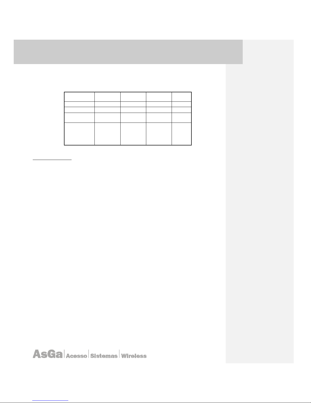
AsGa Light
AsGa LightAsGa Light
AsGa LightBBBBolt 10GigE Switch
olt 10GigE Switcholt 10GigE Switch
olt 10GigE Switch
UUUUser Guide
ser Guideser Guide
ser Guide Commands
CommandsCommands
Commands
75
results determine which address bits are to be considered in processing the traffic. A 0 indicates that
the address bits must be considered (exact match); a 1 in the mask is a "don't care".
The Table shows an example of wildcard or inverse mask use:
IP Address 172 16 32 0
Binary format 10101100 00010000 00100000 00000000
Network Mask 11111111 11111111 11100000 00000000
Wildcard
00000000 00000000 00011111 11111111
Result
Take all bits
as match
creteria
Take all bits
as match
criteria
Take only
the first 3
bits as
matching
criteria
Dont care
Command Syntax
• Syntax for MAC ACls
AsGa (config)# access-list <MAC ACL number> (deny|permit) [(Source =
<SMAC> | Any); SMASK] [(destination = <DMAC>; MASK)].
deny Specify packets to reject.
permit Specify packets to permit
SMAC Source host's MAC address in HHHH.HHHH.HHHH format.
SMASK Source mask in HHHH.HHHH.HHHH format.
any Source any.
DMAC Destination host's MAC address in HHHH.HHHH.HHHH format.
DMASK Destintion mask in HHHH.HHHH.HHHH format.
• Syntax for Standard ACL
AsGa(config)# access-list < standar ACL number> (deny|permit|remark) [SAIP = <A.B.C.D> wildcards = <A.B.C.D> | host <A.B.C.D>].
deny Specify packets to reject.
permit Specify packets to forward.
remark Access list entry comment.
host A single host address. In this case no wildcards is needed.
A.B.C.D Address to match.
A.B.C.D Wildcard bits.
• Syntax for Extended ACL
AsGa (config)# access-list < extended ACL number> (deny|permit|remark);
protocol = <protocol ID>; [(SA-IP = <A.B.C.D> wildcard = <A.B.C.D> | any |
host <A.B.C.D>)]; [DA-IP = <A.B.C.D> wildcards = <A.B.C.D> | any | host
<A.B.C.D>)]
deny Specify packets to reject
permit Specify packets to forward
remark Access list entry comment

AsGa Light
AsGa LightAsGa Light
AsGa LightBBBBolt 10GigE Switch
olt 10GigE Switcholt 10GigE Switch
olt 10GigE Switch
UUUUser Guide
ser Guideser Guide
ser Guide Commands
CommandsCommands
Commands
76
<0-255> An IP protocol number
ahp Authentication Header Protocol
eigrp Cisco EIGRP routing protocol
esp Encapsulation Security Payload
gre Cisco GRE tunneling
icmp Internet Control Message Protocol
igmp Internet Gateway Message Protocol
igrp Cisco's IGRP routing protocol
ip Any Internet Protocol
ipinip IP in IP tunneling
ospf OSPF routing protocol
pcp Payload Compression Protocol
pim Protocol Independent Multicast
tcp Transmission Control Protocol
udp User Datagram Protocol
A.B.C.D Source address
A.B.C.D Source wildcard bits
any Any source host
host A single source host
A.B.C.D Source address
A.B.C.D Destination address
A.B.C.D Destination wildcard bits
any Any destination host
host A single destination host
A.B.C.D Destination address
AsGa (config)# access-list < extended ACL number> (deny|permit|remark);
<tcp|udp>; ID>; [(SA-IP = <A.B.C.D> wildcard = <A.B.C.D> | any | host
<A.B.C.D>)]; [DA-IP = <A.B.C.D> wildcards = <A.B.C.D> | any | host
<A.B.C.D>)]; <src | dest> (eq|gt|lt|neq) PORT
deny Specify packets to reject
permit Specify packets to forward
remark Access list entry comment
tcp Transmission Control Protocol
udp User Datagram Protocol
A.B.C.D Source address
A.B.C.D Source wildcard bits
any Any source host
host A single source host
A.B.C.D Source address
A.B.C.D Destination address
A.B.C.D Destination wildcard bits
any Any destination host
host A single destination host
A.B.C.D Destination address
src Source (TCP/UDP) port
eq Equal
gt Greater than
lt Less than
neq Not equal
PORT Port number <0-65535>

AsGa Light
AsGa LightAsGa Light
AsGa LightBBBBolt 10GigE Switch
olt 10GigE Switcholt 10GigE Switch
olt 10GigE Switch
UUUUser Guide
ser Guideser Guide
ser Guide Commands
CommandsCommands
Commands
77
Command Mode
Config mode
Default
No access lists are configured.
Examples
Related Commands
Mac access-group
Ip access-group
Class maps
4.2 Acces-Group commands
4.2.1 mac access-group
Use the mac access-group interface configuration command to apply a MAC access control list
(ACL) to a interface. Use the <no> statementof this command to remove all MAC ACLs or the
specified ACL from the interface. Create the MAC ACL by using the mac access-list extended global
configuration command.
When an inbound packet is received on an interface with a MAC ACL applied, the switch
checks the match conditions in the ACL. If the conditions are matched, the switch forwards or drops
the packet, according to the ACL action.
If the specified ACL does not exist, the switch forwards all packets.
Command Syntax
mac access-group <mac-ACL number> in
no mac access-group <mac-acl number>
Command Mode
Interface configuration
Examples
Related Commands
Mac access-list
4.2.2 ip acc ess-Group
Use the ip access-group interface configuration command to control access to a Layer 2 or
Layer 3 interface. Use the <no> statement of this command to remove all access groups or the
specified access group from the interface.
You can apply any kind of standard or extended access lists to an interface. To define an
access list by name, use the ip access-list global configuration command. To define a numbered
access list, use the access list global configuration command. You can use numbered standard
access lists ranging from 1 to 99 and 1300 to 1999 or extended access lists ranging from 100 to 199
and 2000 to 2699.

AsGa Light
AsGa LightAsGa Light
AsGa LightBBBBolt 10GigE Switch
olt 10GigE Switcholt 10GigE Switch
olt 10GigE Switch
UUUUser Guide
ser Guideser Guide
ser Guide Commands
CommandsCommands
Commands
78
For standard inbound access lists, after the switch receives a packet, it checks the source
address of the packet against the access list. IP extended access lists can optionally check other
fields in the packet, such as the destination IP address, protocol type, or port numbers. If the access
list permits the packet, the switch continues to process the packet. If the access list denies the packet,
the switch discards the packet.
Command Syntax
ip access-group <access-list-number | name>; <{in | out>
no ip access-group <access-list-number | name>; <in | out>
access-list-number: The number of the IP access control list (ACL), from 1 to 199 or from 1300
to 2699
name: The name of an IP ACL, specified in the ip access-list global configuration command
in: Specify filtering on inbound packets
out:Specify filtering on outbound packets
Command Mode
Interface configuration
Examples
Related Commands
Access-list
Mac-access-group

AsGa Light
AsGa LightAsGa Light
AsGa LightBBBBolt 10GigE Switch
olt 10GigE Switcholt 10GigE Switch
olt 10GigE Switch
UUUUser Guide
ser Guideser Guide
ser Guide Commands
CommandsCommands
Commands
79
B
4.3 Boot
Use this command to change your booting parameters:
Command Syntax
Boot {system | config | AsGOS } file-name
System change your booting system image.
Config change your current booting configuration file.
AsGos change your AsGos booting file.
Command Mode
Exec mode
Default
By default the system boot using a default.txt configuration file and its default system image file.
Examples
AsgOS(config)#boot
AsgOS(config)#boot system LightBolt-28322-E1-L2-System-1.0.0-RC3.bin
AsgOS(config)# show boot
Config File:
Startup: AsGa-conf-2
Running: AsGa-conf-2
Last Modified: Mon Apr 7 12:56:13 2036
AsGOS Image:
Startup: LightBolt-28322-E1-L2-AsGOS-1.0.0-RC4.bin
Running: LightBolt-28322-E1-L2-AsGOS-1.0.0-RC4.bin
Last Modified: Thu Apr 3 08:34:12 2036
System Image:
Startup: LightBolt-28322-E1-L2-System-1.0.0-RC3.bin
Running: LightBolt-28322-E1-L2-System-1.0.0-RC2.bin
Last Modified: Tue Apr 1 08:45:23 2036
Sanity Image:
Startup: LightBolt-28322-E1-L2-Sanity-1.0.0-RC1.bin
Last Modified: Tue Apr 1 08:45:23 2036
AsgOS(config)#
Related Commands
show boot

AsGa Light
AsGa LightAsGa Light
AsGa LightBBBBolt 10GigE Switch
olt 10GigE Switcholt 10GigE Switch
olt 10GigE Switch
UUUUser Guide
ser Guideser Guide
ser Guide Commands
CommandsCommands
Commands
80
C
4.4 Clear counters
Use this privileged command to clear all system counters.
Command Syntax
Clear counters { <IFNAME> | all}
IFNAME: Specify a particular interface name (GE or XE)
All: Clear all system counter
Command Mode
Eexec
Default
No default for this command
Examples
AsGOS# clear counters ge1
Or
AsGOS# clear counters all
Related Commands
No related commands.
4.5 Clear mac-address-table
Command Syntax
clear mac-address-table (dynamic | static)(address mac-address | interface ifname
| vlan vilan-id <1-4094>|)
clear "Reset functions"
mac-address-table "MAC forwarding table"
static "Static entries"
dynamic "Dynamic entries"
address "Address keyword"
MAC "MAC address in HHHH.HHHH.HHHH format"
interface "Interface keyword"
IFNAME "Interface name"
vlan "VLAN keyword"
<1-4094> "VLAN id"

AsGa Light
AsGa LightAsGa Light
AsGa LightBBBBolt 10GigE Switch
olt 10GigE Switcholt 10GigE Switch
olt 10GigE Switch
UUUUser Guide
ser Guideser Guide
ser Guide Commands
CommandsCommands
Commands
81
Command Mode
Exec mode
Examples
Related Commands
Show mac-address
4.6 Class Map Command
Use the class-map global configuration command to name and to isolate a specific traffic
flow from all other traffic. The class map defines the criteria to use to match against a specific traffic
flow to further classify it. Match statements can include criterion such as an ACL, IP precedence
values, or DSCP values. The match criterion is defined with one match statement entered within the
class-map configuration mode.
Command Syntax
class-map [match-all | match-any | match-all-flows] class-map-name
match-all: (Optional) Perform a logical-AND of all matching statements under this class map. All
criteria in the class map must be matched.
match-any: (Optional) Perform a logical-OR of the matching statements under this class map. One
or more criteria must be matched.
match-all-flows: (Optional) used to define a full matching for all flows no other statements are
defined when this type of matching is used.
class-map-name: Name of the class map.
Command Mode
Global configuration mode
Default
No class maps are configured by default.
Usage
Use this command to specify the name of the class for which you want to create or modify class-map
match criteria and to enter class-map configuration mode.
The class-map command and its subcommands are used to define packet classification, as part of a
globally named service policy applied on a per-interface basis.
description: describes the class map. The show class-map privileged EXEC command displays
the description and the name of the class-map.
exit: exits from QoS class-map configuration mode.
match: configures classification criteria used under the named Class-map:
Use the match class-map configuration command to define the match criteria to classify traffic. Use
the <no> statement of this command to remove the match criteria.
[p3] Comentário:
Up to xxx characters

AsGa Light
AsGa LightAsGa Light
AsGa LightBBBBolt 10GigE Switch
olt 10GigE Switcholt 10GigE Switch
olt 10GigE Switch
UUUUser Guide
ser Guideser Guide
ser Guide Commands
CommandsCommands
Commands
82
match {access-group acl-index-or-name | class-map class-map-name | ip dscp
dscp-list | ip precedence ip-precedence-list | vlan vlan-list}
no match {access-group acl-index-or-name | class-map class-map-name | ip
dscp dscp-list | ip precedence ip-precedence-list | vlan vlan-list}
access-group acl-index-or-name: Number or name of an IP standard or extended access
control list (ACL) or MAC ACL.
class-map class-map-name: Name of predefined class map for classification that is performed
on a per-port per-VLAN basis.
ip dscp dscp-list: List of up to eight IP Differentiated Services Code Point (DSCP) values to
match against incoming packets. Separate each value with a space. The range is 0 to 63.
ip precedence ip-precedence-list: List of up to eight IP-precedence values to match
against incoming packets. Separate each value with a space. The range is 0 to 7.
vlan vlan-list: List of VLANs to match against incoming packets. You can enter up to 30 VLAN
IDs. Use a hyphen for a range of VLANs. A VLAN range is counted as two VLAN IDs. Use a space to
separate individual VLANs. The range is 1 to 4094.
no: removes a match statement from a class map.
rename: renames the current class map. If you rename a class map with a name that is already in
use, this message appears:
A class-map with this name already exists
Examples
Related Commands
D
4.7 Dir
Use the <dir> command to display a list of files on your system.
Command Syntax
Dir
Command Mode
Exec mode
Default
No default
Examples
AsGOS#dir
-rw-r--r-- 1 1000 users 7.5M Jul 10 2007 asgos-ver1.0.bin
-rw-r----- 1 root root 3.1k Jul 10 2007 AsGOS.conf
-rw-r--r-- 1 root root 2.4k Jun 29 19:05 sanity.log
-rw-r--r-- 1 root root 2.4k Jun 19 11:51 production.log
-rw-r----- 1 root root 2.3k Jun 15 19:18 default.conf

AsGa Light
AsGa LightAsGa Light
AsGa LightBBBBolt 10GigE Switch
olt 10GigE Switcholt 10GigE Switch
olt 10GigE Switch
UUUUser Guide
ser Guideser Guide
ser Guide Commands
CommandsCommands
Commands
83
Flash disk space:
Used Available Use%
7.7M 24.3M 24%
Related Commands
4.8 Duplex
Use the duplex interface configuration command to specify the duplex mode of operation for
Gigabit Ethernet ports. Use the <no> statement of this command to return the port to its default value.
Command Syntax
duplex {full | half | auto}
full Port is in full-duplex mode.
Half Port is in half-duplex mode.
Auto Port automatically detects whether it should run in full- or half-duplex mode.
no duplex
Command Mode
Interface
Default
All interfaces are set to auto as default command.
Examples
AsGOS# configure terminal
AsGOS(config)# interface ge2
AsGOS(interface)# duplex half
Related Commands
E
4.9 Erase
Use this command to erase the configuration file and restore it to its defaults values.
Command Syntax
erase
Command Mode
Configure mode

AsGa Light
AsGa LightAsGa Light
AsGa LightBBBBolt 10GigE Switch
olt 10GigE Switcholt 10GigE Switch
olt 10GigE Switch
UUUUser Guide
ser Guideser Guide
ser Guide Commands
CommandsCommands
Commands
84
Default
No default for this command
Examples
LightBolt(config)# erase
LightBolt(config)#
4.10 Exit
Use the exit VLAN configuration command to implement the proposed new virtual LAN (VLAN)
into the local database.
Command Syntax
No special arguments for this command
Command Mode
Vlan database
Default
This command has no default values.
Examples
AsGOS(config-vlan)# exit
AsGOS#
Related Commands
Vlan database
F
4.11 Flowcontrol
Use the flowcontrol interface configuration command to set the receive or send flow-control
value for an interface. When flow control send is on for a device and it detects any congestion at its
end, it notifies the link partner or the remote device of the congestion by transmitting a pause frame.
When flow control receive is on for the remote device and it receives a pause frame, it stops
transmitting any data packets. This prevents any loss of data packets during the congestion period.
Use the <receive off> and <send off > keywords to disable flow control.
Command Syntax
flowcontrol < send | receive > <on | off>

AsGa Light
AsGa LightAsGa Light
AsGa LightBBBBolt 10GigE Switch
olt 10GigE Switcholt 10GigE Switch
olt 10GigE Switch
UUUUser Guide
ser Guideser Guide
ser Guide Commands
CommandsCommands
Commands
85
flowcontrol IEEE 802.3x Flow Control
send Flow control on send
receive Flow control on receive
on Turn on flow control
off Turn off flow control
Command Mode
Interface
Usage
Flowcontrol send on
Flowcontrol receive on
Examples
LightBolt# configure t
LightBolt(configure) interface ge1
LightBolt(interface) flowcontrol send on
LightBolt(interface) flowcontrol receive on
Related Commands
No flowcontrol
H
4.12 Hostname
Command Syntax
Command Mode
Default
Examples
Related Commands

AsGa Light
AsGa LightAsGa Light
AsGa LightBBBBolt 10GigE Switch
olt 10GigE Switcholt 10GigE Switch
olt 10GigE Switch
UUUUser Guide
ser Guideser Guide
ser Guide Commands
CommandsCommands
Commands
86
I
4.13 Interface
Use the interface global configuration command to enter in the configuration mode for a
physical interface or to create or access switch virtual interface (SVI) and automatically enter interface
configuration mode. Use the no interface vlan form of this command to delete an SVI.
SVIs are created the first time you enter the interface vlan vlan command for a particular vlan.
The vlan corresponds to the VLAN-tag associated with data frames 802.1q encapsulated trunk or the
VLAN ID configured for an access port.
interface {interface-id | vlan vlan-id}
no interface {interface-id | vlan vlan-id}
Command Mode
Configure mode
Default
No default value.
Examples
AsGOS# configure terminal
AsGOS(config)# interface ge2
AsGOS(interface)#
AsGOS# configure terminal
AsGOS(config)# interface vlan1.200
AsGOS(interface-vlan)#
Related Commands
show interface
shutdown
4.14 Ip address
Use the ip address interface configuration command to set an IP address for the Layer 2 switch
or an IP address for each switch virtual interface (SVI) or routed port on the Layer 3 switch. Use the
<no> statement of this command to remove an IP address or to disable IP processing.
Command Syntax
ip address <ip-address>/< subnet-mask>
no ip address [ip-address / subnet-mask]
Command Mode
Interface

AsGa Light
AsGa LightAsGa Light
AsGa LightBBBBolt 10GigE Switch
olt 10GigE Switcholt 10GigE Switch
olt 10GigE Switch
UUUUser Guide
ser Guideser Guide
ser Guide Commands
CommandsCommands
Commands
87
Default
No default sets for this command.
Examples
AsGOS# configure terminal
AsGOS(config)# interface ge2
AsGOS(interface)# ip address 10.10.10.10/23
AsGOS# configure terminal
AsGOS(config)# interface vlan1.200
AsGOS(interface-vlan)# ip address 10.10.10.10/23
Related Commands
4.15 Ip-access-group
Use the ip access-group interface configuration command to control access to a Layer 2
interface. Use the <no> statementof this command to remove all access groups or the specified
access group from the interface.
Command Syntax
ip access-group {access-list-number } {in | out}
no ip access-group [access-list-number] {in | out}
Command Mode
Interface configuration
Default
No default for this command
Examples
LightBOLT(config)# interface ge1
LightBOLT (config-if)# ip access-group 101 in
Related Commands
access list

AsGa Light
AsGa LightAsGa Light
AsGa LightBBBBolt 10GigE Switch
olt 10GigE Switcholt 10GigE Switch
olt 10GigE Switch
UUUUser Guide
ser Guideser Guide
ser Guide Commands
CommandsCommands
Commands
88
M
4.16 Mac-address-table aging-time
Use the mac address-table aging-time global configuration command to set the length of time
that a dynamic entry remains in the MAC address table after the entry is used or updated. Use the
<no> statement of this command to return to the default setting. The aging time applies to all VLANs.
The default value for this time is 300 seconds.
Command Syntax
mac-address-table aging-time (<0-0>|<10-1000000>)
mac-address-table MAC forwarding table"
aging-time Time a learned mac address will persist after
last update:
<0-0> Enter 0 to disable aging"
<10-1000000> Aging time in seconds"
Command Mode
Config mode
Usage
mac-address-table aging-time 10
Examples
LightBolt# configure t
LightBolt(configure)# mac-address-table aging-time 10
Related Commands
no mac-address-table aging-time
show mac-address-table aging-time
4.17 Mac-address-table freeze
This command permit to freeze the learning process of the mac table. All mac address learned
will persist until the <no> statementof this command will be issue or a reboot process occurs.
Command Syntax
mac-address-table freeze
mac-address-table MAC forwarding table
freeze Freeze changes in mac-address table
Command Mode
Exec mode

AsGa Light
AsGa LightAsGa Light
AsGa LightBBBBolt 10GigE Switch
olt 10GigE Switcholt 10GigE Switch
olt 10GigE Switch
UUUUser Guide
ser Guideser Guide
ser Guide Commands
CommandsCommands
Commands
89
Usage
mac-address-table freeze
Examples
LightBolt# configure t
LightBolt (configure)# mac-address-table freeze
Related Commands
no mac-address-table freeze
4.18 Mac-address-table static
Use the mac address-table static global configuration command to add static addresses to the
MAC address table. Use the <no> statement of this command to remove static entries from the table.
Command Syntax
mac-address-table static MAC vlan <1-4094> interface IFNAME
mac-address-table MAC forwarding table
static Add a static entry
MAC MAC address in HHHH.HHHH.HHHH format
vlan Select a VLAN id
<1-4094> VLAN id
interface Select a interface
IFNAME Interface name
Command Mode
Exec mode
Usage
mac-address-table static 0001.fa09.0909 vlan 20 interface ge1
Examples
LightBolt#configure t
LightBolt(configure)# mac-address-ta
S
4.19 Switchport
Use this command to put a port as switched port. By default all ports in LightBolt switches are
switched ports. You can negate this using <no switchport> command and put the interface in routed
mode operation.

AsGa Light
AsGa LightAsGa Light
AsGa LightBBBBolt 10GigE Switch
olt 10GigE Switcholt 10GigE Switch
olt 10GigE Switch
UUUUser Guide
ser Guideser Guide
ser Guide Commands
CommandsCommands
Commands
90
Command Syntax
Switchport
Command Mode
Configure mode interface mode
Default
No switchport.
At Startup all port are switched port and all port are access port attached to VLAN 1. All ports are also
attached to Bridge Group 1 running classic Spanning Tree Protocol (802.1D).
Examples
AsGOS# configure terminal
AsGOS(config)# interface ge2
AsGOS(interface)# switchport.
Related Commands
4.20 Switchport mode
Use the switchport mode interface configuration command to configure the VLAN membership
mode of a port. Use the <no> statementof this command to reset the mode to the appropriate default
for the device.
Command Syntax
Switchport mode {access | trunk | hybrid}
no switchport mode
Access: Set the port to access mode. The port is set to access unconditionally and operates as a
nontrunking, single VLAN interface that transmits and receives non-tagged frames. An access port
can be assigned to only one VLAN.
Trunk: Set the port to trunk unconditionally. The port is a trunking VLAN Layer-2 interface. The port
transmits and receives encapsulated (tagged) frames that identify the VLAN of origination. A trunk is a
point-to-point link between two switches or between a switch and a router. AsGa LightBolt switches
use 802.1Q tag encapsulation method.
Hibrid: This mode set the trunk in an hybrid mode witch means that the port acting as a trunk has a
default VLAN for all those packet witch arrive at the port untagged. Under this mode the user must
specify the untagged VLAN for all those arriving non tagged packets. Out going packet for the
specified VLAN ID will go out from this trunk in an untagged form.
In addition: for this VLAN; this port act as an access port.
Under the hybrid mode the default VLAN is specified using the following sentence:
AsGos (interface ge16) switchport hybrid vlan <VLAN ID>
VLAN ID = 1-4095
And then the user must specify the non tagged nature of this VLAN for this port using the following
command:

AsGa Light
AsGa LightAsGa Light
AsGa LightBBBBolt 10GigE Switch
olt 10GigE Switcholt 10GigE Switch
olt 10GigE Switch
UUUUser Guide
ser Guideser Guide
ser Guide Commands
CommandsCommands
Commands
91
AsGos (interface ge16) switchport hybrid allowed vlan add <VLAN ID> egresstagged disable
VLAN ID =1-4095
Command Mode
Configure mode interface mode
Default
No default.
Examples
AsGOS# configure terminal
AsGOS(config)# interface ge2
AsGOS(interface)# switchport mode trunk
AsGOS(interface)# switch port allowed vlan all
AsGos (interface ge16)
AsGos (interface ge16) switchport
AsGos (interface ge16) switchport mode hybrid
AsGos (interface ge16) switchport hybrid vlan 101
AsGos (interface ge16) switchport mode hybrid acceptable-frame-type all
AsGos (interface ge16) switchport hybrid allowed vlan add 100 egress-tagged enable
AsGos (interface ge16) switchport hybrid allowed vlan add 101 egress-tagged
disable
AsGos (interface ge16) switchport hybrid allowed vlan add 200 egress-tagged enable
Related Commands
Switchport
4.21 Switchport access
Use the switchport access interface configuration command to configure a port as a staticaccess If the mode is set to access, the port operates as a member of the configured virtual LAN
(VLAN). Use the <no> statement of this command to reset the access mode to the default VLAN for
the switch.
Command Syntax
switchport access { vlan <vlan-id> | vlan-staking}
vlan ID: Per port VLAN ID configured for this port. Range 2:4093.
Vlan-staking: use this command to enable vlan staking on a particular port (Q in Q method). All
frames will be tagged on top of the existing tag (Customer Tag) with the VLAN ID configured under
this port. Port must be an access port in order to enable vlan staking on it.
Command Mode
Configure mode interface mode
Default
No default.

AsGa Light
AsGa LightAsGa Light
AsGa LightBBBBolt 10GigE Switch
olt 10GigE Switcholt 10GigE Switch
olt 10GigE Switch
UUUUser Guide
ser Guideser Guide
ser Guide Commands
CommandsCommands
Commands
92
Examples
AsGOS# configure terminal
AsGOS(config)# interface ge2
AsGOS(interface)# switchport access vlan 200
AsGOS(interface)#switchport access vlan-staking
Related Commands
vlandatabase
VLAN
Switchport mode
4.22 Switchport trunk
Use the switchport trunk interface configuration command to set the trunk characteristics when
the interface is in trunking mode. Use the <no> statementof this command to reset all of the trunking
characteristics to the defaults. Use the no form with keywords to reset that characteristic to the
defaults. The encapsulation method for AsGa switches is based on 802.1Q tagging.
Command Syntax
switchport trunk [allowed vlan <allowed vlan ID list>]
vlan ID: 2:4093
Command Mode
Configure mode interface mode
Default
All VLAN´s ID are allowed by default
Examples
AsGOS# configure terminal
AsGOS(config)# interface ge2
AsGOS(interface)# switchport trunk allowed vlan 2,3,4,300
Related Commands
vlandatabase
VLAN
Switchport mode
4.23 Switchport mode trunk ingress filter
Use the switchport mode trunk interface configuration command to configure the VLAN filtering
mode of a port. Under this command just only those VLANs defined will be accepted by this trunk
port. Any non taggued frame will be discarded.
Command Syntax
Switchport mode trunk ingress filter <enable | disable>

AsGa Light
AsGa LightAsGa Light
AsGa LightBBBBolt 10GigE Switch
olt 10GigE Switcholt 10GigE Switch
olt 10GigE Switch
UUUUser Guide
ser Guideser Guide
ser Guide Commands
CommandsCommands
Commands
93
Command Mode
Interface mode
Default
The ingress filter is disable by default
Examples
interface ge12
switchport
bridge-group 1
switchport mode trunk
switchport mode trunk ingress-filter enable
switchport trunk allowed vlan add 300
bridge-group 1 instance 1
bridge-group 1 instance 2
!
4.24 Speed
Use the speed interface configuration command to specify the speed of a port. Use the <no> or
default form of this command to return the port to its default value. 10 GigE interfaces has no option
for this command. Those interfaces work only at 10Gig Ethernet standard.
Command Syntax
speed <10 | 100 | 1000| auto>
10 Port runs at 10 Mbps.
100 Port runs at 100 Mbps.
1000 Port run at 1000 Mbps
auto Port automatically detects the speed it should run at based on the
port at the other end of the link
no speed
Command Mode
Interface
Default
All interfaces are set to auto as default command.
Examples
AsGOS# configure terminal
AsGOS(config)# interface ge2
AsGOS(interface)# speed 100
Related Commands
Interface

AsGa Light
AsGa LightAsGa Light
AsGa LightBBBBolt 10GigE Switch
olt 10GigE Switcholt 10GigE Switch
olt 10GigE Switch
UUUUser Guide
ser Guideser Guide
ser Guide Commands
CommandsCommands
Commands
94
4.25 Show Interface
Use the show interface privileged EXEC command to display the administrative and operational
status of a port.
Command Syntax
show interface <interface-id>
Command Mode
Default
No default sets for this command.
Examples
AsGOS# show interface
hw link speed/ auto max link MAC
interface type stat duplex neg? frame scan address
ge1 ETH down - yes 1522 SW ge2 ETH down - yes 1522 SW ge3 ETH down - yes 1522 SW ge4 ETH down - yes 1522 RT 00.f6.04.aa.00.06
ge5 ETH down - yes 1522 RT 00.f6.04.aa.00.07
ge6 ETH down - yes 1522 RT 00.f6.04.aa.00.08
ge7 ETH down - yes 1522 RT 00.f6.04.aa.00.09
ge8 ETH down - yes 1522 RT 00.f6.04.aa.00.0a
ge9 ETH down - yes 1522 RT 00.f6.04.aa.00.0b
ge10 ETH down - yes 1522 RT 00.f6.04.aa.00.0c
ge11 ETH down - yes 1522 RT 00.f6.04.aa.00.0d
ge12 ETH down - yes 1522 RT 00.f6.04.aa.00.0e
ge13 ETH down - yes 1522 RT 00.f6.04.aa.00.0f
ge14 ETH down - yes 1522 RT 00.f6.04.aa.00.10
ge15 ETH down - yes 1522 RT 00.f6.04.aa.00.11
ge16 ETH down - yes 1522 RT 00.f6.04.aa.00.12
ge17 ETH down - yes 1522 RT 00.f6.04.aa.00.13
ge18 ETH down - yes 1522 RT 00.f6.04.aa.00.14
ge19 ETH down - yes 1522 RT 00.f6.04.aa.00.15
ge20 ETH down - yes 1522 RT 00.f6.04.aa.00.16
ge21 ETH down - yes 1522 RT 00.f6.04.aa.00.17
ge22 ETH down - yes 1522 RT 00.f6.04.aa.00.18
ge23 ETH down - yes 1522 SW ge24 ETH down - yes 1522 SW lo LB up - yes 1500 RT 00.00.00.00.00.00
vlan1.1 VLAN - - yes 1522 - 00.f6.04.aa.00.02
vlan1.20 VLAN - - yes 1522 - 00.f6.04.aa.00.02
vlan1.100 VLAN - - yes 1522 - 00.f6.04.aa.00.02
xe1 ETH down 10G FD no 1522 RT 00.f6.04.aa.00.1b
xe2 ETH down 10G FD no 1522 RT 00.f6.04.aa.00.1c
AsGOS# show interface ge1
hw link speed/auto max link MAC
interface type stat duplex neg? frame scan address
ge1 ETH down - yes 1522 SW -

AsGa Light
AsGa LightAsGa Light
AsGa LightBBBBolt 10GigE Switch
olt 10GigE Switcholt 10GigE Switch
olt 10GigE Switch
UUUUser Guide
ser Guideser Guide
ser Guide Commands
CommandsCommands
Commands
95
Related Commands
4.26 Show Interfaces
Use the <show interfaces> privileged EXEC command to display various counters for the
switch or for all interfaces o for a specific interface.
Command Syntax
AsGOS# show interfaces ge1
AsGOS# show interfaces
Command Mode
EXEC
Default
No default for this command
Examples
AsGOS#show interfaces
-----------------------------------------------------
Interface name.................................: ge1
Total Packets Received (Octets)................: 0
Total Packets Received Without Errors..........: 0
Total Packets Received Discarded...............: 0
Total Packets Transmitted (Octets).............: 5312
Total Packets Transmitted Successfully.........: 83
Total Packets Transmitted Errors...............: 0
-----------------------------------------------------
Interface name.................................: ge2
Total Packets Received (Octets)................: 0
Total Packets Received Without Errors..........: 0
Total Packets Received Discarded...............: 0
Total Packets Transmitted (Octets).............: 5312
Total Packets Transmitted Successfully.........: 83
Total Packets Transmitted Errors...............: 0
-----------------------------------------------------
Interface name.................................: ge3
Total Packets Received (Octets)................: 0
Total Packets Received Without Errors..........: 0
Total Packets Received Discarded...............: 0
Total Packets Transmitted (Octets).............: 5312
Total Packets Transmitted Successfully.........: 83
Total Packets Transmitted Errors...............: 0
Still showing all other interfaces counters.
AsGOS# show interfaces ge1
Interface name.................................: ge1
Total Packets Received (Octets)................: 0
Total Packets Received Without Errors..........: 0

AsGa Light
AsGa LightAsGa Light
AsGa LightBBBBolt 10GigE Switch
olt 10GigE Switcholt 10GigE Switch
olt 10GigE Switch
UUUUser Guide
ser Guideser Guide
ser Guide Commands
CommandsCommands
Commands
96
Unicast Packets Received.......................: 0
Multicast Packets Received.....................: 0
Broadcast Packets Received.....................: 0
Total Packets Transmitted (Octets).............: 7168
Total Packets Transmitted Successfully.........: 112
Unicast Packets Transmitted....................: 0
Multicast Packets Transmitted..................: 112
Broadcast Packets Transmitted..................: 0
Total RX and TX Octets.........................: 7168
Packets RX and TX 64 Octets....................: 112
Packets RX and TX 65-127 Octets................: 0
Packets RX and TX 128-255 Octets...............: 0
Packets RX and TX 256-511 Octets...............: 0
Packets RX and TX 512-1023 Octets..............: 0
Packets RX and TX 1024-1518 Octets.............: 0
Packets RX and TX > 1518 Octets................: 0
802.3x Pause Frames Received...................: 0
802.3x Pause Frames Transmitted................: 0
Total Packets Received Not Forwarded...........: 0
Total Packets Received Discarded...............: 0
Jabbers Received...............................: 0
Fragments/Undersize Received...................: 0
Oversized packets..............................: 0
Alignment Errors...............................: 0
FCS Errors.....................................: 0
Too Long Frames Errors.........................: 0
Total Packets Transmitted Errors...............: 0
Total Packets Transmitted Discarded............: 0
Single Collision Frames........................: 0
Multiple Collision Frames......................: 0
Excessive Collision Frames.....................: 0
Related Commands
4.27 Shutdown
Use the shutdown interface configuration command to disable an interface. Use the <no>
statement of this command to restart a disabled port or switch virtual interface (SVI).
The <shutdown> command for a port causes it to stop forwarding. You can enable the port
with the <no shutdown> command. The <shutdown> command disables all functions on the specified
interface.
Command Syntax
shutdown
no shutdown
Command Mode
Interface

AsGa Light
AsGa LightAsGa Light
AsGa LightBBBBolt 10GigE Switch
olt 10GigE Switcholt 10GigE Switch
olt 10GigE Switch
UUUUser Guide
ser Guideser Guide
ser Guide Commands
CommandsCommands
Commands
97
Default
No default for this command.
Examples
AsGOS# configure terminal
AsGOS(config)# interface ge1
AsGOS(interface)# shutdown
Related Commands
Interface
Interface vlan1<VLAN ID>
4.28 Show VLAN
Use the show vlan user EXEC command to display the parameters for all configured virtual
LANs.
Command Syntax
AsGOS# show vlan <all | VLANID> bridge <bridge ID>
Command Mode
EXEC
Default
No Default for this command.
Examples
AsgOS#show vlan all bridge 1
Bridge VLAN ID Name State Member ports
(u)-Untagged, (t)-Tagged
---------------------------------------------------------------------------------1 1 default ACTIVE ge1(u) ge2(u) ge3(u) ge4(u)
ge5(u) ge6(u) ge7(u) ge8(u)
ge9(u) ge10(u) ge11(u) ge12(u)
ge13(u) ge14(u) ge15(u)
ge16(u) ge17(u) ge18(u)
ge19(u) ge20(u) ge21(u)
ge22(u) ge23(u) ge24(u) xe1(u)
xe2(u) xe3(u) xe4(u)
Related Commands

AsGa Light
AsGa LightAsGa Light
AsGa LightBBBBolt 10GigE Switch
olt 10GigE Switcholt 10GigE Switch
olt 10GigE Switch
UUUUser Guide
ser Guideser Guide
ser Guide Commands
CommandsCommands
Commands
98
4.29 Show outbound access-priority-table
Use this command to display data about the access-priority table. To modify the lines
displayed, use the | (output modifier token); to save the output to a file, use the > output redirection
token. For more information, see the AsGOS Command Line Interface Environment chapter.
Command Syntax
show outbound access-priority-table interface IFNAME
IFNAME Specify the name of the interface.
Command Mode
Privileged Exec mode
Usage
AsGOS# show outbound access-priority-table interface eth4
802.3 Format Outbound Access Priority
1
0
0
0
0
0
0
4.30 Show traffic-class-table
Use this command to display the data in the traffic class table.
To modify the lines displayed, use the | (output modifier token); to save the output to a file,
use the > (output redirection token). For more information, see AsGOS Command Line Interface
Environment.
Command Syntax
show traffic-class-table interface IFNAME
IFNAME Specify the name of the interface.
Command Mode
Privileged Exec mode
Usage
The following is a display of this command showing the traffic class table for interface eth1.
AsGOS# show traffic-class-table interface eth1
User Prio / Num Traffic Classes
1 2 3 4 5 6 7 8
0 0 0 0 0 0 0 0 0
1 0 0 0 0 0 0 0 0
2 0 0 0 0 0 0 0 0
3 0 0 0 0 0 0 0 0
4 0 0 0 0 0 0 0 0
5 0 0 0 0 0 0 0 0
6 0 0 0 0 0 0 0 0

AsGa Light
AsGa LightAsGa Light
AsGa LightBBBBolt 10GigE Switch
olt 10GigE Switcholt 10GigE Switch
olt 10GigE Switch
UUUUser Guide
ser Guideser Guide
ser Guide Commands
CommandsCommands
Commands
99
Examples
AsGOS# show traffic-class-table interface eth1
Related Commands
4.31 Show user-priority
Use this command to display the user priority data. To modify the lines displayed, use the |
(output modifier token); to save the output to a file, use the > (output redirection token). For more
information, see AsGOS Command Line Interface Environment.
Command Syntax
show user-priority interface IFNAME
Command Mode
Privileged Exec mode
Usage
The following is output display of this command showing set user priority for interface eth4.
AsGOS# show user-priority interface eth4
Default user priority : 7
Examples
AsGOS# show user-priority interface eth0
Related Commands
4.32 Storm Control
To enable broadcast, multicast, or Destination Lookup Failure (DLF) storm control on a
particular port, use the <storm-control> command in interface configuration mode. To disable storm
control for broadcast, multicast, or DLF traffic, use the <no> statementof this command.
Command Syntax
storm-control < broadcast | dlf | multicast> < level>
broadcast: type this key to limit the maximum broadcast traffic to be admitted by a specific port.
dlf: is the maximum throughput of dlf (destination lookup failure) to be forwarded/admitted by a
specific port. A dlf occur each time that a no MAC address match is accomplished.
multicast: use this key to limit the maximum multicast traffic to be admitted by a specific port.
level: specify the maximum level of the specific traffic admitted by a specific port. This level is
intended to be a % of the maximum speed of the port.

AsGa Light
AsGa LightAsGa Light
AsGa LightBBBBolt 10GigE Switch
olt 10GigE Switcholt 10GigE Switch
olt 10GigE Switch
UUUUser Guide
ser Guideser Guide
ser Guide Commands
CommandsCommands
Commands
100
Command Mode
Interface mode
Usage
AsGOS(config-if)#storm-control broadcast <% of the maximum Speed Port>
Examples
AsGOS(config-if)#storm-control broadcast 30
AsGOS(config-if)#storm-control dlf 50
AsGOS(config-if)#storm-control multicast 10
Related Commands
4.33 Snmp-server manager
Use the snmp-server host global configuration command to specify the recipient (host) of a
Simple Network Management Protocol notification operation. Use the <no> statement of this
command to remove the specified host. UP to five host can be provisioned.
Command Syntax
snmp-server manager ip-address traps-version ( ( 1 | 2c ) community
community | 3 ( noauth | auth | priv ) username ) ( udp-port port | )
snmp-server Configure parameters to SNMP Agent
manager Set manager configuration to send traps
ip-address IP address of a manager
traps-version Set the traps version
1 Traps version 1
2c Traps version 2
community: Set the community string for
SNMPv1/v2c transactions
community Communnity string
3 Traps version 3
noauth No authorization
auth Authorization
priv Privative
username Username
udp-port Set the port to send SNMP traps
port UDP Port number
Command Mode
Config mode
Usage
LightBOLT(config)# snmp-server manager ip-address (traps-version ( 1 | 2c | 3 user
username (auth | noauth | priv) | ) (community string | ) (upd-port port | )
 Loading...