

Aseptico ARU-01 Maintenance manual

P.O. Box 1548 Woodinville, WA 98072-1548
1-800-426-5913 * 425-487-3157 * Fax: 360-668-8722
email: info@aseptico.com * Internet: www.aseptico.com
P/N 420263
Rev. A
05/00
OPERATION AND
MAINTENANCE MANUAL
ARU-01CF
NSN: 6525-01-468-1672

Page 2
Table of Contents
Introduction . . . . . . . . . . . . . . . . . . . . . . . . . . . . . . . . . . . . . . . . . . . . . . . . . . . . . . . . . . . . .3
Purpose . . . . . . . . . . . . . . . . . . . . . . . . . . . . . . . . . . . . . . . . . . . . . . . . . . . . . . . . . .3
Performance Characteristics . . . . . . . . . . . . . . . . . . . . . . . . . . . . . . . . . . . . . . . . . .3
Items Furnished . . . . . . . . . . . . . . . . . . . . . . . . . . . . . . . . . . . . . . . . . . . . . . . . . . .3
Safety Precautions . . . . . . . . . . . . . . . . . . . . . . . . . . . . . . . . . . . . . . . . . . . . . . . . . . . . . . . .4
Assembly . . . . . . . . . . . . . . . . . . . . . . . . . . . . . . . . . . . . . . . . . . . . . . . . . . . . . . . . . . . . . . .5
Performance Verification . . . . . . . . . . . . . . . . . . . . . . . . . . . . . . . . . . . . . . . . . . . . . . . . . . .6
Line Voltage Indicator . . . . . . . . . . . . . . . . . . . . . . . . . . . . . . . . . . . . . . . . . . . . . .6
Timer . . . . . . . . . . . . . . . . . . . . . . . . . . . . . . . . . . . . . . . . . . . . . . . . . . . . . . . . . . . .6
Peak Tube Potential . . . . . . . . . . . . . . . . . . . . . . . . . . . . . . . . . . . . . . . . . . . . . . . .8
Tube Current . . . . . . . . . . . . . . . . . . . . . . . . . . . . . . . . . . . . . . . . . . . . . . . . . . . . . .8
Testing Checklist . . . . . . . . . . . . . . . . . . . . . . . . . . . . . . . . . . . . . . . . . . . . . . . . . . .9
Operation Instructions . . . . . . . . . . . . . . . . . . . . . . . . . . . . . . . . . . . . . . . . . . . . . . . . . . .10
Operation . . . . . . . . . . . . . . . . . . . . . . . . . . . . . . . . . . . . . . . . . . . . . . . . . . . . . . .10
Technique Chart . . . . . . . . . . . . . . . . . . . . . . . . . . . . . . . . . . . . . . . . . . . . . . . . . .11
Maintenance . . . . . . . . . . . . . . . . . . . . . . . . . . . . . . . . . . . . . . . . . . . . . . . . . . . . . . . . . . .12
Component Data . . . . . . . . . . . . . . . . . . . . . . . . . . . . . . . . . . . . . . . . . . . . . . . . . . . . .13-16
Table of Illustrations
Figure A - Component Identification . . . . . . . . . . . . . . . . . . . . . . . . . . . . . . . . . . . . . . . . .5
Figure B - Potentiometer Location . . . . . . . . . . . . . . . . . . . . . . . . . . . . . . . . . . . . . . . . . . .6
Figure C - Electrical Pulse Activity During X-Ray Tube Warm-up and Exposure . . . . . .7
Figure D - X-Ray Tube Electrical Performance . . . . . . . . . . . . . . . . . . . . . . . . . . . . . . . . .8
Chart A - Testing Checklist . . . . . . . . . . . . . . . . . . . . . . . . . . . . . . . . . . . . . . . . . . . . . . . . .9
Figure E - Control Panel . . . . . . . . . . . . . . . . . . . . . . . . . . . . . . . . . . . . . . . . . . . . . . . . . .10
Chart B - Technique Chart . . . . . . . . . . . . . . . . . . . . . . . . . . . . . . . . . . . . . . . . . . . . . . . .11
Figure F - Absolute Maximum Rating Charts . . . . . . . . . . . . . . . . . . . . . . . . . . . . . . . . .14
Figure G - Emission and Filament Characteristics . . . . . . . . . . . . . . . . . . . . . . . . . . . . . .14
Figure H - Anode Thermal Characteristics . . . . . . . . . . . . . . . . . . . . . . . . . . . . . . . . . . .14
Figure I - Dimensional Outline . . . . . . . . . . . . . . . . . . . . . . . . . . . . . . . . . . . . . . . . . . . . .15
Figure J - Schematic Diagram . . . . . . . . . . . . . . . . . . . . . . . . . . . . . . . . . . . . . . . . . . . . . .16
Upon Arrival
When the equipment is received, each shipping container should be carefully examined for any
evidence of mishandling during shipment. Note its condition, if abnormal, carefully unpack all
parts and examine for damage. If any damage is noted, immediately report it to the carrier in the
proper manner. All printed matter supplied with the unit should be saved for installation,
operation, and future reference.

Page 3
Introduction
Purpose
The ARU-01CF Command Air X-ray System provides a portable and practical way to obtain
dental radiographs in the field. To receive the best service and longest life from your Aseptico
product, follow the instructions detailed in this manual.
Performance characteristics
Weight: . . . . . . . . . . . . . . . . . . . . . . . . . . . .42 lbs.
Size (external): . . . . . . . . . . . . . . . . . . . . .17.5” x 16” x 17”, 2.75 cubic feet
Maximum peak tube potential
1
: . . . . . . . .63kVp ± 15%
Leakage technique factors: . . . . . . . . . . . .63 kVp 12 mA 2 sec.
Range of line voltage regulator: . . . . . . . .110 - 130 V AC (220 - 260 V AC), 50/60 Hz.
Current at 12 mA, 63 kVp output: . . . . . .6 Amps
Line voltage regulation
2
: . . . . . . . . . . . . . .2 ~ 5%
Generator rating
3
: . . . . . . . . . . . . . . . . . . .12 mA at 63 kVp ± 15%
Duty cycle: . . . . . . . . . . . . . . . . . . . . . . . . .30 : 1
Maximum deviation from fixed factors: . .± 15%
X-ray tube: . . . . . . . . . . . . . . . . . . . . . . . . .Type D-082B Manufactured by Toshiba
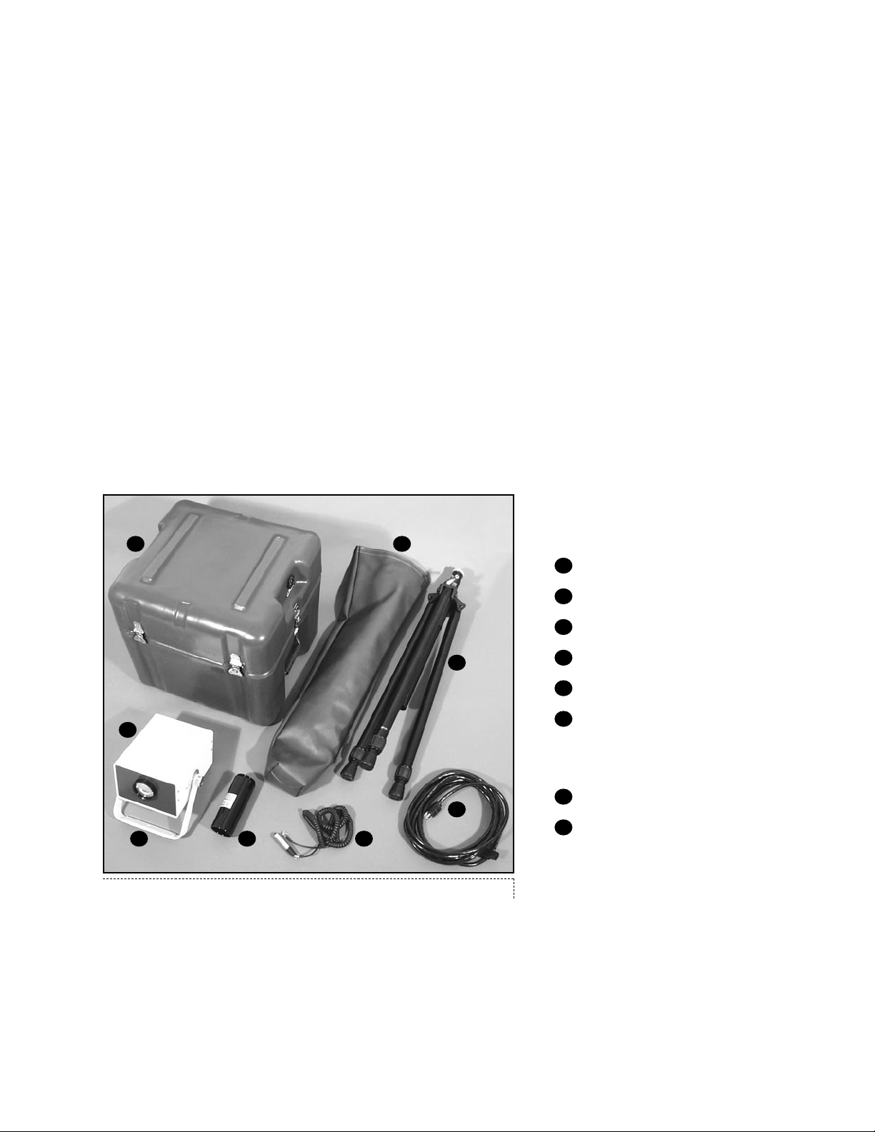
Items furnished
X-ray tubehead and control
Mounting handle
Dental cone
Exposure cord
Power cord
Mil-spec case with shock resistant foam insert
ARU-01S tripod
Vinyl carrying case
Manual
1
Measurements taken with a 50mm diameter sphere gap.
2
The stated mA and line current are under conditions of input line voltage of 110 - 130 V (220 - 260 V)
with 2 ~ 5% regulation. If regulation is less, the amps drawn and mA can be higher than stated.
3
Using a precise DC mA meter across points N and NE of the high tension transformer (see schematic
diagram) to measure mA. Input is 117 V AC (230 V AC), 50/60 Hz. Tolerance is ± 15%.

Page 4
Safety Precautions
WARNING - Careless or improper use of x-ray equipment can be extremely hazardous.
WARNING - It is imperative that this equipment be operated and serviced only by trained
personnel familiar with the safety precautions required to prevent excessive exposure
to primary x-ray radiation, the dangers of exposure to x-ray radiation, and the proper
use of the equipment discussed in this manual.
1. During exposure, the operator must stand as far as possible from the patient being x-rayed
and should wear a lead apron or stand behind a lead shield.
2. The operator must not stand in the primary x-ray beam.
3. The operator must wear a monitoring badge while operating this unit. It should be on the
collar, not on an area covered by the lead apron.
4. X-ray exposure should be as short as possible.
All personnel authorized to operate or service this equipment should be fully acquainted with the
established maximum permissible doses, safety recommendations, and procedures derived from
the following sources:
A. National Council on Radiation Protection Report No. 33 (Medical X-ray and Gamma Ray
Protection for Energies up to 10 MEV - Equipment Design and Use); from NCRP
Publications; P.O. Box 30175, Washington, D.C. 20014.
B. National Bureau of Standards Handbook No. 76 (Medical X-ray Protection up to Three
Million Volts); from the Superintendent of Documents, Government Printing Office,
Washington, D.C. 20401.
C. All documents relating to the Performance Standard for Diagnostic X-ray Systems, 21 CFR
Subchapter J, Part 1020; obtainable from FDA Center for Devices and Radiological
Health, Department of HHS, 2098 Gaither Road, Rockville, MD 20850.
D. State and local regulations governing radiation protection and the use of diagnostic x-ray
equipment.
E. Requirements of the user's in-house radiation protection program.
F. Instructions and precautionary notices of this manual.
Although this equipment incorporates protective design features for limiting both the direct
(primary) x-ray beam and the secondary radiation produced by this beam, design factors alone
cannot prevent human carelessness, negligence, or lack of knowledge. This apparatus is sold with
the understanding that the user assumes sole responsibility for radiation safety and that Aseptico,
Inc., its agent and representatives, do not accept any responsibility for:
1. Injury or danger to patient or other personnel from x-ray exposure.
2. Overexposure due to poor operating techniques or procedures.
3. Equipment not properly serviced or maintained in accordance with this manual.
4. Equipment which has been modified or tampered with in any way.
Page 5
X-ray tubehead and control
Mounting handle
Dental cone
Exposure cord
Power cord
ARU-01S tripod
Includes:
#510311 5/16 - 18 wing-nut
#510322 5/16 fender washer
Vinyl carrying case
Mil-spec case with shock
resistant foam insert
1
2
3
4
1
2 3 4
Figure A - Component Identification
Assembly
1. Remove the x-ray tube head and control, cone, exposure cord, and power cord from the
carrying case.
2. Screw the cone on to the front of the tubehead.
3. Plug the exposure cord into the rear of the tubehead.
4. Plug the power cord into the rear of the tubehead
5. Set up tripod
6. Attach the assembled x-ray unit to the stand.
7. Check the line voltage and the voltage on the rating label;
115 V type requires line voltage between 110 and 130 V.
230 V type requires line voltage between 220 and 260 V.
These voltages must be with 15 ampere #12 three-wire service, if not,
the films may be light or show lack of sufficient penetration.
8. Plug the power cord into the wall outlet.
The unit is now assembled and ready for testing.
5
6
7
8
5
6
78
Page 6
Performance Verification
The following tests must be conducted without fail before the ARU-01CF Command Air X-Ray
System can be used for radiology. Fill out the checklist for these tests when installation of x-ray
unit is complete.
Line Voltage (LV) Indicator
1-1 LV Indicator Test Method:
Measure voltage of wall outlet, and confirm that the following conditions are fulfilled.
Wall outlet voltage:
130 ~ 125 V (260 ~ 250 V) Green LED goes on when LV knob turns 1 click clockwise.
125 ~ 120 V (250 ~ 240 V) Green LED goes on when LV knob turns 2 clicks clockwise.
120 ~ 115 V (240 ~ 230 V) Green LED goes on when LV knob turns 3 clicks clockwise.
115 ~ 110 V (230 ~ 220 V) Green LED goes on when LV knob turns 4 clicks clockwise.
110 ~ 105 V (220 ~ 210 V) Green LED goes on when LV knob turns 5 clicks clockwise.
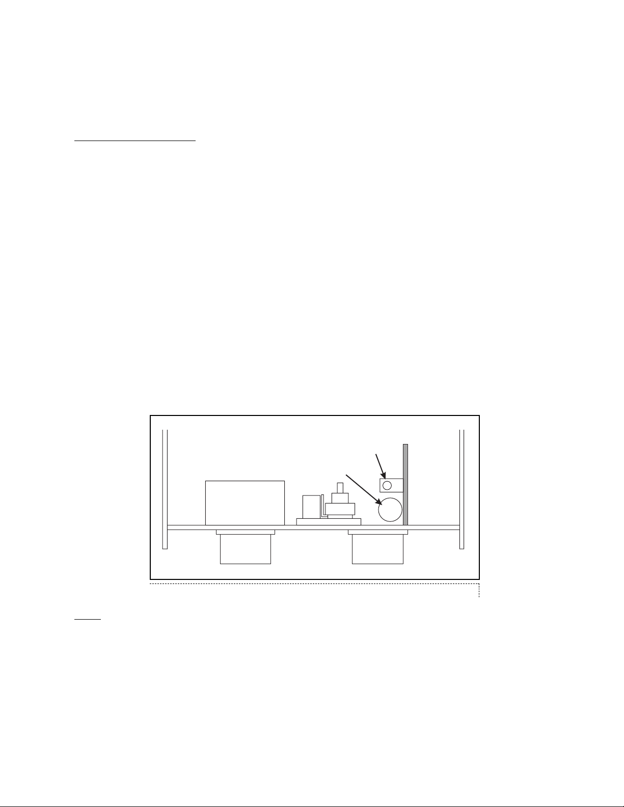
If the LV indicator needs adjustment:
1. Remove the 4 screws on the cover.
2. Adjust the potentiometer "A" (See Figure B) on the printed circuit board so that the green
LED goes on at the above settings.
3. Replace the cover and the 4 screws.
Timer
Since the filament of the x-ray tube is off when the unit is not emitting radiation, it takes
approximately 0.15 seconds (9 electrical pulses) for the x-ray tube filament to warm up be fore an
x-ray is emitted (see Figure C). Because of this warm up time, the electronic timer has a built in
lag of approximately 0.15 seconds, therefore, when checking the timer with a cycle counter, 0.15
seconds must be added to the time set on the timer.
+
-
A
B
Figure B - Potentiometer Location
 Loading...