

Aseptico ADU-10CF User manual

SERVICE
MANUAL
&
(NSN:
PARTS
ADU-10CF
6520-01-456-7170)
LIST
Part I of
2
P.O.
Box
1548
Woodinville,
1-800-426-5913 * 425-487-3157 * Fax:
email:
info@aseptico.com * Internet:
WA
98072-1548
425-487-2608
www.aseptico.com
12/98
P/N
420218
TABLE
OF
CONTENTS
General
Inspection & Verification
Cleaning & Lubrication
Dis-Assembly
Handpiece
Vacuum
Fiber
TA-97 3-Way
Troubleshooting
System
System
Illustrated
e
Vacuum
Case
HVE & Saliva
NWS-6
TA-97
AA-42
Air
Swivel
KaVo
Service
System/Water
Optic
Schematic;
Schematic;
e
Control
Components
Information
Control/Delivery
System
Syringe
Chart
Handpiece
Vacuum
Parts
List
aç
...
Ejector
Water
System
Autoclavable 3-Way
Standard
Supply
Tray
Fiber
Disc
Line
Assembly
Assembly
Optic
System
...
System
...
..
Assembly
Foot
..
Head . .
Control
Control
Control
MV
Syringe
Control
.
. .
..
.
...
..
.
...
.
le
lc SÜ e e
Specilienil0ns...
TABLE
Handpiece
Vacuum
Fiber
3-Way
System
System
Illustrated
Illustrated
Illustrated
Illustrated
Illustrated
System/Water
Optic
Syringe
Schematic,
Schematic,
Illustrated
Illustrated
Illustrated
Swivel
Tray
KaVo
Fiber
s1...
OF
ILLUSTRATIONS
Control/Delivery
System
.
Parts
List,
Parts
List,
Parts
List,
List,
Parts
List,
Parts
List,
Parts
List,
Parts
List,
Parts
Assembly
Optic
saunaya
System
..
ADU-10CF
ADU10CF
Handpiece
Vacuum
Case
Components
&
HVE
NWS-6
TA-90
AA-42
Supply
Air
System
A
Head
Control
Handpiece
Vacuum
Control
Saliva
Water
Autoclavable
Standard
Control
Control
....
Ejector
System
Disc
Assembly
Line
...
Control
..
3-Way
nes
.
Assembly
..
Syringe
Control
Foot
vie a ara
..
..
.......
dia a а
еее
196
2
Box
P.O.
1-800-426-5913
info@aseptico.com
email:
Woodinville,
1548
425-487-3157
*
*
WA
*
Internet:
www.aseptico.com
98072-1548
425-487-2608
Fax:
Printed
In
The
USA
GENERAL
This
service
Operation
Portable
schematics
coded
listed
that
Use
Field
by
color
in
reverse
can
be
information
the
SERVICE
and
parts
and
Maintenance
Dental
show
components
tone
and
numerical
purchased
in
manual
Unit
line
order
at
retail
Parts
the
INFORMATION
offers
manual.
works,
in
thickness,
hardware
information
thereby
there
actual
in
the
when
List
It
will
and
Parts
stores,
and
help
reducing
places
all
parts
List.
Parts
and
ordering
parts
lists
you
better
service
in
the
are
minimize
replacement
time.
unit
called
marked
service
out
not
available
understand
Exploded
relative
as
parts.
to
one
by
Aseptico
"Commercial"
delays
in
how
parts
another.
part
when
the
ADU-10CF
the
ADU-10CF
drawings
Tubing
number,
are
those
obtained
and
is
then
items
locally.
Inspection
To
verify
that
air
source
pressure
turned
from
three-way
the
to
on
the
While
performance.
Element
Water
require
tube.
container
screen
The
above
not
perform
service.
various
providing
gauge
on,
water
highspeed
the
syringe.
system,
position.
system
should
canister
lubrication
Water
filter
lids
should
describes a basic
as
Use
the
problems.
&
Operation
the
ADU-10CF
60-80
PSI.
and
"On"
indicator
canister
Syringe
the
lift
Vacuum
is
pressurized,
Air
filterAvater
be
replaced
should
or
requires
should
be
inspected
required,
troubleshooting
should
and
line,
should
and
HVE
should
when
be
holding
replacement
replacement
be
sealed
for
inspection & verification
further
Verification
unit
is
functioning
Switch
should
pressurize.
lowspeed
spray
Saliva
inspect
separator
blockage
Ejector
switch
the
pressure
pressure
for a proper
and
holding a vacuum
diagnosis
section
the
master
indicate
Depress
when
line
both
air
valve
vacuum
and
on,
unit
for
drain
should
drop
at
if
it
becomes
and
cleaned
of
settings
as a guide
properly,
On/Off
pressure.
foot
selected.
and
water.
from
air
or
water
be
across
the
lid,
seal.
Inspect
clogged
or
of
and
to
symptoms
connect
toggle
When
control
Depress
With
vacuum
auto
their
generated
leaks
closed,
the
unit
exceeds
and
the
lid
the
and
restricts
when
in
replaced
the
if
ADU-10CF
components
and
the
unit
to
to
the
on
the
water
and
observe
air/water
the
waste
holders
each
at
that
and
gasket
water
operation.
necessary.
appropriate
with
valve.
could
air
filter
10psi
inspected.
filter
water
system.
in
the
a
clean
compressed
position.
system
containers
degrade
element
differential
on
flow.
HVE
If
system
The
is
attached
drive
air
buttons
out
lock
or
Gasket
the
water
Vacuum
solids
the
unit
may
procedures
master
and
pressure
the
on
attached
switch
eliminate
inspected.
pressure.
collector
still
in
may
pick-up
waste
does
require
to
fix
Cleaning
When
thoroughly
cleaner.
finishes
Use a silicone
parts,
o-rings,
assembly
installation
and
servicing
cleaned
Flush
all
and
should
oral
of
parts
easier
Lubrication
the
ADU-10CF
and
parts
with
be
avoided.
base
lubricating
evacuator
that
contain
and
prevent
dental
inspected
clear,
hot
Any
grease
valves,
o-rings
the
o-rings
unit,
before
water.
wiping
such
and
seals
or
seals,
or
the
parts
of
any
component
re-assembly. A hot
Abrasive
should
as
in
seals
cleaners
be
done
with a soft,
Dow
Corning
the
ADU-10CF
apply a light
from
coat
being
have
No.103
damaged.
detergent
the
potential
lint
to
lubricate
unit.
Before
of
silicone
disassembled
solution
free
grease.
is
an
to
damage
cloth.
internal
performing
This
should
will
be
effective
surface
moving
any
re-
make
Page
3
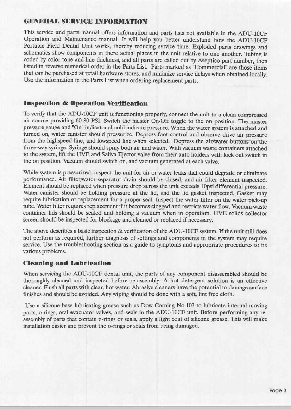
DIS-ASSEMBLY
Handpiece
Most
cover(P/N
6-32x1/4"
Disconnect
If
the
four
remove
the
four
Head
Re-assembly
Control/Delivery
all
service
460311-08).
socket
pressure
entire
Handpiece
mounting
Handpiece
10-32x1/2"
assembly
is
screws
while
Control/Delivery
Vacuum
To gain
from
the
use a 1/8"
washers.
To
vacuum
signal
System/Water
access
its
to
mounting
Vacuum/Water
Hex
Support
completely
remove
pick-up
lines.
(Reference
Head
to
the
Handpiece
To
remove
screws
beneath
gauge
and
Control/Delivery
behind
Control/Delivery
socket screws
removing
done
in
the
reverse
Head
assembly.
System
internal
position
wrench
the
tubes,
parts
in
the
System
Control.
to
loosen
Vacuum/Water
the
Vacuum/Water
the
3/8"
Figure
2A)
(Reference
Control/Delivery
front
cover,
the
front
edge.
On/Off
Indicator
Head
the
Handpiece
Head
assembly,
and
#10
sealing
mounting
screws.
order.
Align
front
Control
of
case.
(Reference
the
Vacuum/Water
Locate
To
remove
and
remove
System
System
air
supply
line,
Figure
1)
Head
use a 5/64"
Pull
front
lines
to
assembly
can
Hex
cover
completely
must
Control/Delivery
use a 1/8"
washers.
Replace
cover
with
Figure
the
four
Handpiece
the
four
Control
Control
the
1/4"
Support
sealing
rear
2)
System
Control,
mounting
Vacuum/Water
10-32x1/2"
assembly
from
handpiece
be
accessed
wrench
to
straight
remove
be
removed
Head
Hex
washers
on
wrench
the
Handpiece
when
alignment
you
screws
on
socket
while
removing
the
case,
air
supply
by
loosen
off
front
from
the
to
mounting
pins
when
must
the
System
screws
you
line,
removing
and
remove
rear
alignment
the
the
cover.
the
case,
locate
back
of
the
case.
loosen
and
remove
Control/Delivery
Handpiece
replacing.
remove
top
mounting
must
the
of
the
case
Control
and
#10
screws.
disconnect
and
the
assembly
assembly,
sealing
air
front
two
pins.
the
To
above
the
pilot
Re-assembly
System
assembly.
is
done
in
the
Reattach
reverse
supply
tubes
order.
per
Replace
vacuum
sealing
control
washers
when
mounting
schematic.(Reference
=
Alignment
Socket
Pins
Screws
Vacuum/Water
Figure
2A)
ige
Figure
Handpiece
4
Control/Delivery
1
Head
Vacuum
Figure
System/Water
2
System
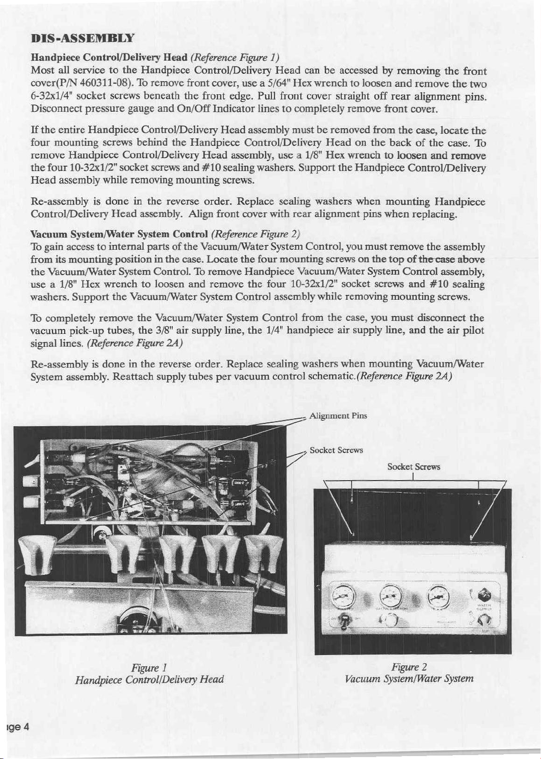
Fiber
Optic
The
ADU-10CF
Control
removal
To
remove
Remote
Control
To
remove
System
is
Module,
for
service
the
Remote
Intensity
cable
from
the
KaVo
Control/Delivery
blade
screwdriver,
the
LCM
control,
handpiece
Handpiece
replacement.
To
remove
and
Remote
Signal
driver,
control,
Hex
Control/Delivery
in
the
tubing
Air
tube
loosen
position
Nuts
holding
reverse
Control/Delivery
Reassembly
the
KaVo
Intensity
from
holding
No.
Head.
order.
(Reference
equipped
Remote
or
Intensity
replacement.
Intensity
Control
the
LCM
LCM
Head
front
loosen
position
Drive
Air,
is
LCM
Control
the
LCM
screws
4(reference
the
LCM
Remove
Figure
with a KaVo
Control,
bracket
control
Handpiece
cover
as
holding
No.
Coolant
screws
4.
Carefully
Head
done
in
Fiber
Optic
cable
control box
for
the
Fig.
control box
LCM
3)
LCM
Control,
and/or
unscrew
underneath
jack
marked
Tubing
described
for
the
slide
Air,
and
Coolant
(reference
the
reverse
Handpiece
from
the
LCM
at
the
low
voltage
12A-Fiber
to
the
mounting
control box
Fiber
Optic
the
KaVo
the
the
delivery
"INT".
from
in
the
first
low
voltage
the
wires
Water
Fig.
1A-System
order.
control
control
position
handpiece
Optic
System
bracket
for
service
Handpiece
LCM
Handpiece
two
4-40x1/4"
head.
Unplug
Reassembly
the
unit,
paragraph
handpiece
out
of
the
tubes
from
Schematic).
box,
first
box.
Disconnect
marked
"HP4".
tubing
Schematic).
in
the
or
replacement.
Lighting
tubing
socket
screws
the
is
done
in
the
first
remove
of this
section.
tubing
wires
delivery head.
their
connections
Remove
unplug
the
the red
With a small
wires
connected
Remove
unit
beneath
Reassembly
System.
The
may
require
holding
Remote
reverse
the
Intensity
order.
Handpiece
With a small
connected
Remove
inside
tubing
transformer
1/8"
Fiber
blade
screw-
to
the
the
two
the
Handpiece
is
LCM
the
to
the
the
for
cable,
Optic
LCM
6-32
done
Remote
Handpiece
Intensity
KaVo
Control
LCM
Tubing
Handpiece
With
HAND + AIR
2)
Figure
Conirol/Delivery
Fiber
3
Optic
System
Head
Low
Voltage
Tubing
Remote
Fiber
KaVo
6-32
Handpiece
Wires
Intensity
Optic
Signal
Box
LCM
Hex
Nut, 2 Pl.
Jack
Air
Page 5
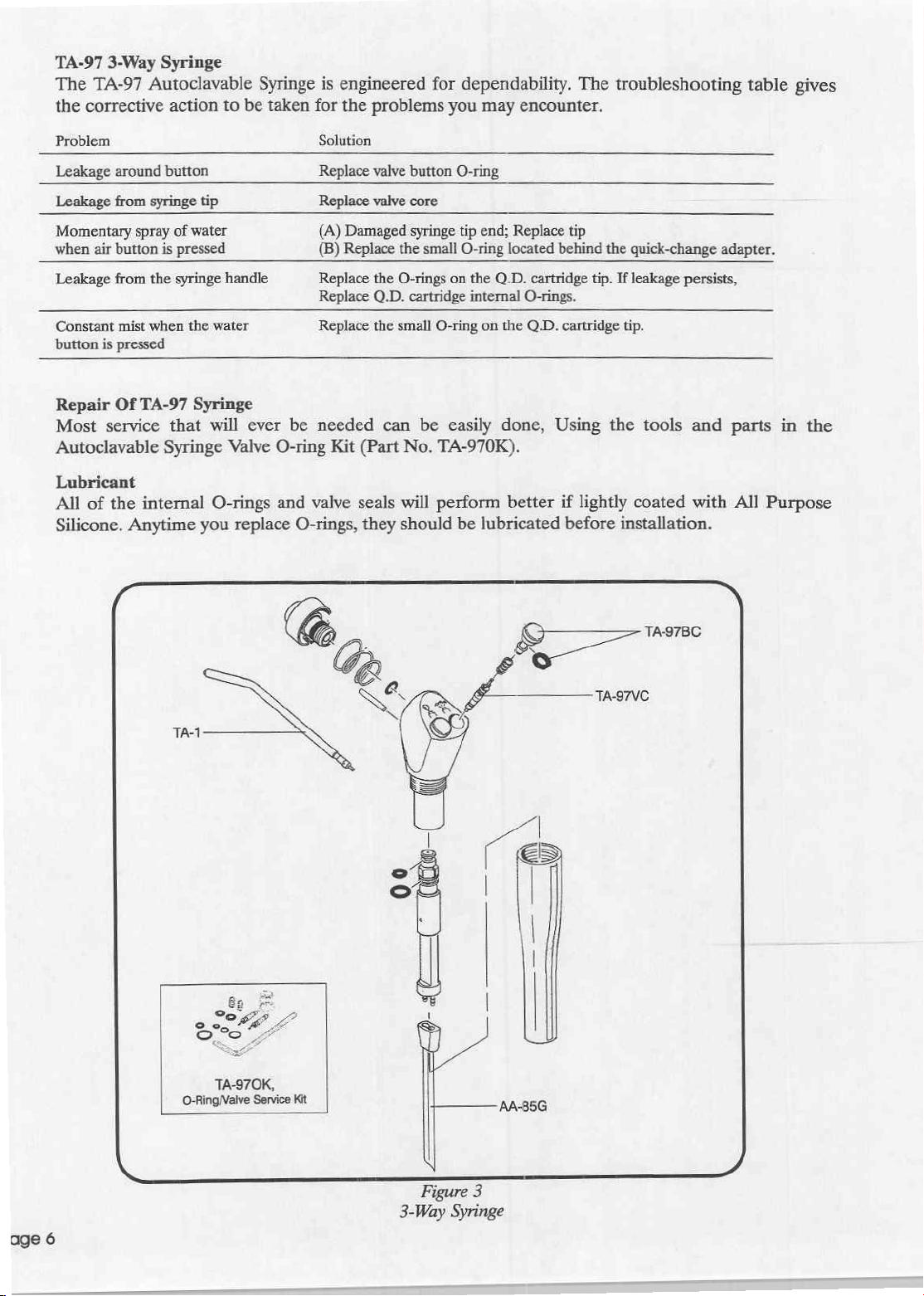
TA-97
The
the
3-Way
TA-97
corrective
Syringe
Autoclavable
action
to
be
Syringe
taken
for
is
engineered
the
problems
for
dependability.
you
may
encounter.
The
troubleshooting
table
gives
Problem
Leakage
Leakage
Momentary
when
Leakage
Constant
button
Repair
Most
Autoclavable
Lubricant
All
Silicone.
around
from
air
button
from
mist
is
pressed
Of
service
of
the
[三
button
syringe
spray
of
is
pressed
the
syringe
when
the
TA-97
that
Syringe
internal
Anytime
tip
water
handle
water
Syringe
will
ever
Valve
O-rings
you replace
Solution
Replace
Replace
(A)
(B)
Replace
Replace
Replace
be
needed
O-ring
and
valve
O-rings,
Damaged
Replace
Kit
(Part
seals
they
valve
button O-ring
valve
core
syringe
the
the
O-rings
Q.D.
cartridge
the
small
can
be
No.
will
should
tip
end;
small
O-ring
on
the
internal
O-ring
on
easily
TA-970K).
perform
be
lubricated
Replace
located
Q.D.
cartridge
O-rings.
the
Q.D.
done,
better
tip
behind
the
quick-change
tip.
If
leakage
cartridge
Using
if
before
tip.
the
lightly
installation.
persists,
tools
coated
adapter.
and
with
a
parts
All
Purpose
in
the
TAA
TA-970K,
O-RingValve
(©
Service
Kit
i
“e
SG
A
TA-97BC
TA-97VC
Massa
Figure
3-Way
3
Syringe
Button
Before
metallic
syringe
Use
installing
Excessive
Do
To
the
Drop
Tip
Remove
Kit
and
Valve
removing
device
body.
the
valve
the
tightening
not
reinstall a used
replace
button
Adapter & Collar
to
the
itself.
the
coil
the
syringe
unscrew
the
such
Be
careful
core
new
valve
O-ring
Push
spring
the
syringe
as a tongue
not
tool
(Part
core,
may
impair
valve
on
the
the
replacement
into
the
tip,
then
tip
adapter.
button,
depressor
to
lose
the
No.
TA-97VT)
do
not
valve
core,
because
syringe
syringe
use
the
Remove
button,
disconnect
or
small
over-tighten
operation.
O-ring
body,
then
hex
key
the
the
Popsicle
coil
to
unscrew
it.
it
will
be
remove
into
carefully
furnished
adapter,
syringe
stick
spring
that
the
It
needs
difficult
the
old
its
groove
with
collar
from
to
is
valve
only
to
O-ring
push
the
and
the
Q.D.
gently
pry
the
located
to
get
on
the
Autoclavable
spring
beneath
core
from
be
snug
it
to
seal
carefully,
the
stem
button
from
cartridge.
button
the
the
syringe
enough
properly.
so as
to
of
the
button.
into
place.
Syringe
the
syringe
Use a non-
valve
out
button.
body.
to
seal
the
avoid
damaging
Valve
body.
of
the
When
bore.
O-ring
Use a dental
syringe
install
into
to
Before
assure
collar
Use
you
the
have
Q.D.
Removing
adapter. A bent
the
the
be
installed
that
with
the
don’t
adapter.
approximately
Cartridge
pick
body.
Be
replacement
bore.
The
with
reinstalling
the
the
pin,
hex
key
have a torque
If
Before
air
and
syringe
the
or a bent
especially
is
to
O-ring
care.
the
adapter
alignment
then
to
you
tighten
performing
water,
O-Rings
paper
pin
push
carefully
measuring
the
right
and
from
clip
paper
clip
careful
slip
around
screw
the
torque.
any
bleed
the
or a dental
not
it
onto
the
and
collar
is
in
place.
the
collar
in
device,
adapter
service
pressure
Q.D.
to
remove
to
nick
the
end
outside
the
as
of
assembly,
With
the
into
the
adapter.
hold
tight
IMPORTANT
on
the
Q.D.
from
the
cartridge
pick
gives
can
the
tiny
O-ring
or
scratch
of a syringe
the
adapter
look
spring
syringe body.
Tighten
the
hex
as
you
cartridge,
system
you
be
used
the
down
in
the
key
can
while
by
access
to
remove
from
the
bottom
sealing
tip,
is
thin
into
place
adapter
by
the
it
is
running a handpiece.
to
surfaces.
lubricate
and
the
in
short
holding
necessary
the
the
the
fragile,
bore
the
collar,
firmly
end, with
the
O-rings
two
O-rings.
O-ring,
so
in
the
align
(35
tool
to
turn
of
the
the
easiest
then
the
new
syringe
the
in-lbs
the
this
way,
off
the
on
bore
in
way
insert
one
body
and
slot
in
torque).
long
end
you
will
the
of
end
the
to
it
has
the
If
in
the
Further
material
disassembly
accumulated
has
of
Q.D.
the
inside
cartridge
upper
the
needed
is
cartridge
body.
only
there
if
There
is
are
reason
no
to
serviceable
believe
parts
foreign
that
inside.
Page
7
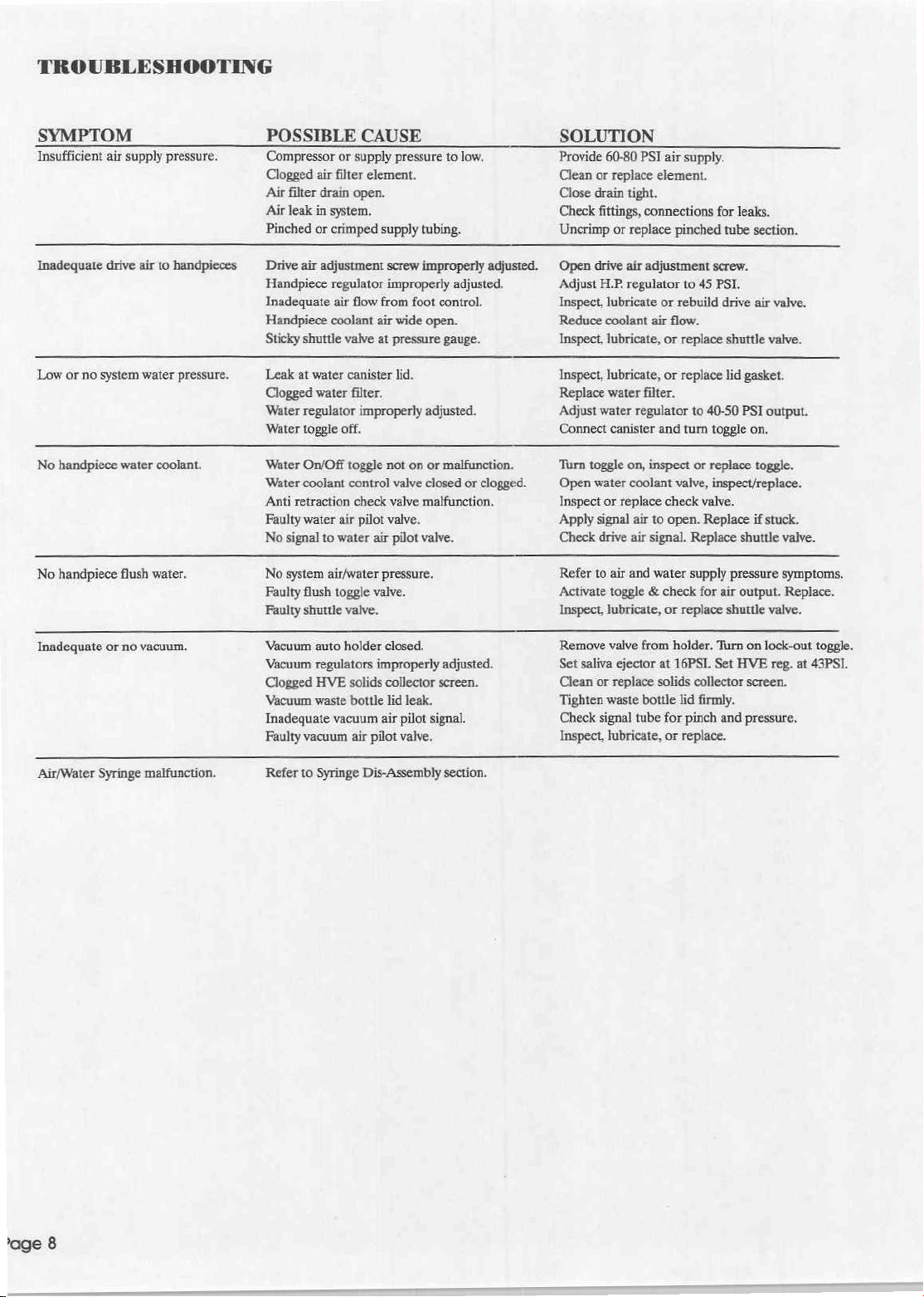
TROUBLESHOOTING
SYMPTOM
Insufficient
Inadequate
Low
No
No
Inadequate
‘Ait/Water
air
supply
drive
air
or
no
system
water
handpiece
handpiece
water
flush
or
no
vacuum.
Syringe
malfunction.
pressure.
to
handpieces
pressure.
coolant.
water.
POSSIBLE
Compressor
Clogged
Air
filter
Air leak
Pinched
Drive
air
Handpiece
Inadequate
Handpiece
Sticky
shuttle
Leak
at
Clogged
Water
regulator
‘Water
toggle
Water
On/Off
Water
coolant
Anti
retraction
Faulty
water
No
signal
No
system
Faulty
flush
Faulty
shuttle
‘Vacuum
‘Vacuum
Clogged
Vacuum
Inadeguate
Faulty
vacuum
Refer
to
CAUSE
or
supply
air
filter
drain
open.
in
system.
or
crimped
adjustment
regulator
air
flow
coolant
valve
water
canister
water
filter.
improperly
off.
toggle
control
check
air
pilot
to
water
air/water pressure.
toggle
valve.
auto
holder
regulators
HVE
solids
waste
bottle
vacuum
air
Syringe
pressure
element.
supply
screw
improperly
from
air
wide
at
pressure
lid.
to
low.
tubing.
improperly
adjusted.
foot
control.
open.
gauge.
adjusted.
not
on
or
malfunction.
valve
closed
or
valve
malfunction.
valve.
air
pilot
valve.
valve.
closed.
improperly
collector
lid
air
pilot
Dis-Assembly
leak.
pilot
signal.
valve.
adjusted.
screen.
section.
SOLUTION
Provide
Clean
Close
Check
Uncrimp
adjusted.
Open
Adjust
Inspect,
Reduce
Inspect,
Inspect,
Replace
Adjust
Connect
Turn
clogged.
Open
Inspect
Apply
Check
Refer
Activate
Inspect,
Remove
Set
Clean
Tighten
60-80
or
replace
drain
tight.
fittings,
or
replace
drive
air
H.P.
regulator
lubricate
coolant
lubricate,
lubricate,
water
water
regulator
canister
toggle
on,
water
coolant
or
replace
signal
air
drive
air
to
air
and
toggle & check
lubricate,
valve
saliva
ejector
or
replace
waste
Check
signal
tube
Inspect,
lubricate,
PSI
air
supply.
element.
connections
adjustment
or
air
or
or
filter.
and
inspect
check
to
open.
signal.
water
or
from
at
solids
bottle
for
or
for
leaks.
pinched
tube
screw.
to
45
PSI.
rebuild
drive
flow.
replace
shuttle
replace
lid
to
40-50
PSI
turn
toggle
or
replace
valve,
inspect/replace.
valve.
Replace
Replace
supply
replace
holder.
16PSI.
pressure
for
air
shuttle
Turn
Set
shuttle
output.
HVE
collector
lid
firmly.
pinch
and
replace.
section.
air
valve.
valve.
gasket.
output.
on.
toggle.
if
stuck.
valve.
symptoms.
Replace.
valve.
on
lock-out
reg.
at
toggle.
43PSI.
screen.
pressure,
‘age
8
ADU-10CF
SCHEMATIC
PARTS
DIAGRAMS
&
LIST
Page
 Loading...