

Page 1
ASCO 5350 Installation Manual
A
Installation Manual
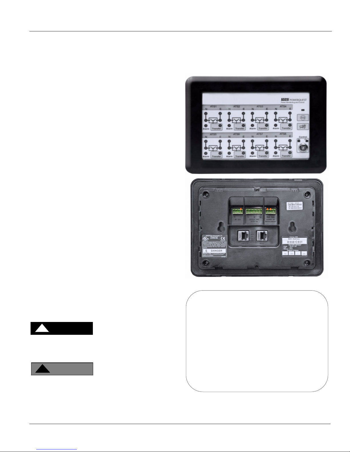
The ASCO 5350 ATS Remote Annunciator is listed under the
Underwriter’s Laboratories Standard UL-1008 for Automatic
Transfer Switch accessories. This stand-alone device provides
individual status monitoring and control of up to eight ASCO
Automatic Transfer Switches (ATSs) over an ethernet
network. Each ATS must have an ASCO 5150 Connectivity
Module (CM) (Acc. 72E) connected to it. Daisy-chained ATSs
that have ASCO 5110 Serial Modules (Acc. 72A) can share a
single CM. The Catalog 5350 can communicate with these
ATSs:
7000 & 4000 Series (Group 5 Controller)
Series 300 (Group 1 Controller)
Series 185 (Group 4 Controller)
ASCO 940 (Group 7 Controller)
The ASCO 5350 complies with US UL requirements. It also
has IEC Certification (CE Mark).
Product Functions and General Descriptions:
Separate light indicate switch status and position.
ATS switch position
ATS source availability
ATS alarm condition
ATS time delay active
ATS Remote Annunciator
Catalog 5350
Separate push buttons individually initiate transfer switch
operation and testing.
ATS transfer test (Transfer)/ bypass (cancel) time delay
Silence alarm
Lamp test
Reset
The ATS Remote Annunciator can also be setup in multiple
locations to monitor the same devices. This arrangement
allows for redundant annunciation of business-critical ATSs.
After the ATS Remote Annunciator is installed and
configured refer to User’s Guide 381333-314.
DANGER
!
DANGER is used in this manual to warn of a
hazard situation which, if not avoided, will result in
death or serious injury.
WARNING
!
WARNING is used in this manual to warn of a
hazardous situation which, if not avoided, could
result death or serious injury.
Rear view
TABLE OF CONTENTS
page
Specifications . 2
Installation . 3
Functional Test . 4
Configuration . 5
TS Configuration . 7
Diagnostics . 10
Troubleshooting . 11
Installation Drawings & Wiring Diagrams
Index . 12
381333-315 D ASCO Power Technologies Page 1
381333-315 D
Page 2
Installation Manual ASCO 5350
Specifications
Power Requirements: 120-220 V ac nominal
(90-264 V ac)
auxiliary 24 V dc nominal (9-36 V dc)
can be a battery or UL rated
Class 1 dc power supply
max. power 10 watts ac or 5 watts dc
Dimensions: 7.77” H x 9.95” L x 2.563” D
(19.74 cm H x 25.27 cm L x 6.51 cm D)
Weight: 2.7 lb. (1.2 kg)
Ethernet Communication Cable Requirements:
Belden 1583A or equiv. UTP CAT 5e or CAT 6
with RJ45 connectors (untwisted pair or higher)
Ethernet Port Connectors:
Two built-in 10/100 Base T (RJ45) 10/100 Mbps
Configuration Parameters:
(The parameters required to make an Ethernet connection)
IP Address 169.254.1.200
Subnet Mask 255.255.0.0
Gateway 0.0.0.0
TCP Port No. 10001
A label on the back shows the default settings.
Protocol Support: ASCO I, II, and Modbus/TCP
Ambient Temperature:
Operating -4 to 158 deg F (-20 to 70 deg C)
@ 5-85 % humidity
Storage -40 to 185 deg F (-40 to 85 deg C)
Number of Channels 8
Internal Alarm Buzzer
Alarm Relay Contact Ratings
contact configuration 1 spst normally open
ac ratings 1 A @ 110/220 V ac 50/60 Hz
1 Factory Default Information
A label on the back to the ATS Remote Annunciator lists
several important settings that you will need to do the
configuration. Write down this information below before
installing it (and after changing these settings).
IP Addr ______________
factory default: 169.254.1.200
Login ______________
factory default: admin and user
(see page 4 for Login names)
Password ______________
factory default: ASCO (capital letters)
Configured IP Address ___ ___ ___ ___
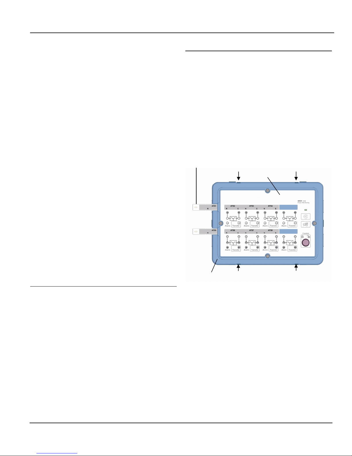
2 Custom ATS Labels
Custom ATS names (instead of numbers) can be added to the
faceplate. See page 6 to enter and print customized names. To
install the custom labels follow these steps:
1. Remove the bezel by using a blade screwdriver. Insert the
screwdriver tip into the four slots between the bezel and
faceplate. Flip the screwdriver to remove the bezel.
2. Slide out the existing ATS labels. Cut the new custom
labels to fit and paste them onto the label holder. Then
slide them back onto the faceplate.
3. Reinstall the bezel by carefully aligning it, then pressing it
in firmly by hand until it snaps on (four places).
label
faceplate
bezel
Figure 1: Custom ATS names (slide in labels)
bezel release
factory default: 169.254.1.200
(customer’s IP address)
Page 2 ASCO Power Technologies 381333-315 D
Page 3

ASCO 5350 Installation Manual
Installation
The ASCO 5350 ATS Remote Annunciator can be panel
mounted or attached to an electrical or masonry gang box.
Refer to the installation drawing 834970 and wiring diagram
834969 at the back of this manual.
DANGER
!
To avoid shock, burns, or death, deenergize all
electrical sources before making connections.
5 Internal Buzzer and Alarm Relay
1 Panel Mounting
Refer to installation drawing 834970 sheet 1. After wiring the
ATS Remote Annunciator, attach it (without the back cover)
directly to the panel cutout. A gasket in the slot in the bezel
provides Ingress Protection (IP51). Four screw adjustable
mounting tabs are provided on the sides. Before inserting it
through the opening, turn the four mounting screws counterclockwise (to turn the tabs flush against the sides). After it is
installed, turn the screws clockwise to extend the tabs, then
tighten the four screws clockwise so that the tabs secure it
from the inside.
To release it, turn the four screws counter-clockwise until the
tabs are loosened and then turn flush against the sides.
2 Gang Box / Masonry Wall
Mounting
Refer to installation drawing 834970 sheet 2. Before inserting
it through the opening, turn the four mounting screws
counterclockwise (to turn the tabs flush against the sides).
After it is installed, turn the screws clockwise to extend the
tabs, then tighten the four screws clockwise so that the tabs
secure it from the inside. Install the wide bezel to cover the
steel plate.
To release it, turn the four screws counterclockwise until the
tabs are loosened and then turn flush against the sides.
Refer to wiring diagram 834969. In addition to the internal
alarm buzzer, a normally-open dry alarm contact is provided
for an external buzzer circuit. An ac buzzer can be wired along
with the main ac power supply. A dc buzzer requires a 24 V
dc power supply and can be wired along with the
communication wiring. See page 6 for configuration of buzzer
operation.
6 Communication Wiring (Ethernet)
Refer to wiring diagram 834969. The communication wiring
and ac power wiring must be isolated. Use Belden 1583A
cable or equivalent UTP CAT 5e or CAT 6 with RJ-45
connectors (untwisted pair or higher). Connect the Ethernet
Ports to the network.
6-1 Communication Architecture
These architectures are applicable for ASCO 5350:
Communication wiring for up to 8 ATSs for Single Location
with individual Connectivity Modules for every ATS
Communication wiring for more than 8 ATSs for multiple
locations with individual Connectivity Modules for every ATS
Communication wiring for up to 32 ATSs for multiple
locations with single Connectivity Module for Group 5
Controller (4000 & 7000 Series)
3 Flush Mounting
For flush mounting in 4-inch or deeper walls, mounting
enclosure kit K871966-003 is required.
4 Power Wiring
A licensed electrician should install the ATS Remote
Annunciator. All national and local codes must be followed.
Refer to wiring diagram 834969. The power terminals accept
30 to 12 AWG stranded flexible wire. If the power wiring is
solid wire, pigtail it with stranded flexible wiring to the ATS
Remote Annunciator. Use a 3 mm flat screwdriver to tighten
the power terminals screws to 5 in-lb. (0.5 Nm) tightening
torque.
381333-315 D ASCO Power Technologies Page 3
Communication wiring for up to 32 ATSs for multiple
locations with single Connectivity Module for Group 1
Controller (Series 300) & Group 5 Controller (4000 & 7000
Series)
Communication wiring for up to 32 ATSs for multiple
locations with single Connectivity Module for Group 7
Controller
(ASCO 940, 962)
NOTE
For best performance limit any RS-485 serial daisy-chain to
eight ATSs. Each ATS Remote Annunciator is capable of
handling a single serial communications string at a time, but is
scalable by adding additional ATS Remote Annunicators.
Page 4
Installation Manual ASCO 5350
Functional Test
After installing the ATS Remote Annunciator communication
must be established to configure it. A Windows-based laptop
computer is needed. You must have access to the other end of
the communication cable that is connected to the ATS Remote
Annunciatior. You also need to know the factory default
settings on the label (see page 2).
1 Initial checks
After the ATS Remote Annunciator is mounted and wired
(both power and communication) perform these tests:
1. Turn on the power to energize the ASCO 5350.
2. Verify that the power light is illuminated (upper right).
3. Turn the Control key switch to the right (unlocked).
4. Press the lamp test button (below the power light); all
lights should illuminate.
2 Communication check
A laptop computer running Windows Xp and Internet Explorer
5.0 + will be used in these steps to configure the ATS Remote
Annunciator. You will need to temporarily disconnect the
other end of the communication cable from the ATS Remote
Annunciator and connect it instead to the laptop computer.
1. Connect the Ethernet cable from the ATS Remote
Annunciator to the laptop computer’s Ethernet jack.
2. Start Windows, click the Start button, then Control Panel.
3. Double click the Network Connections icon.
4. Double click the Local Area Connections icon, then click
Properties.
5. Select Internet Protocol (TCP/IP), then click Properties.
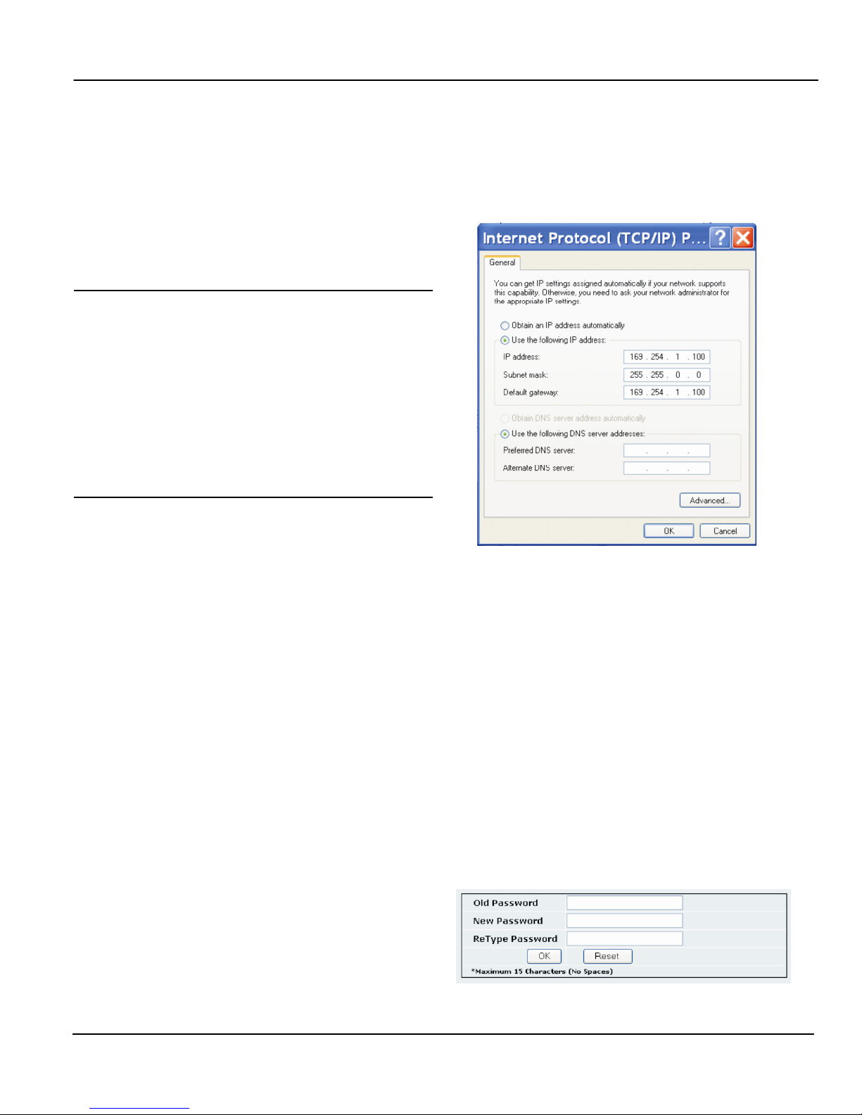
6. Set the IP setting of the laptop computer (see Figure 2):
IP Address 169.254.1.100 (last digit must be
different than ASCO 5350 Default IP)
Subnet Mask 255.255.0.0 (same as ASCO 5350)
Default Gateway leave blank
(This is needed only if communicating to a different LAN.)
7. Click OK and click Close. Close the Local Area
Connection window.
8. Once the TCP/IP setup is complete at the laptop computer,
restart the computer (click Start button, then click
Restart).
9. Restart Windows, then click the Start button. Select All
Programs > Accessories > Command Prompt.
10. In the command prompt window type ipconfig and press
ENTER. The settings are displayed.
11. In the command prompt window type
ping 169.254.1.200 and press ENTER.
You should see: Reply from 169.254.1.200
This reply confirms communication between the laptop
computer and the ATS Remote Annunciator. Close the
command prompt window. Proceed to the Configuration,
Login screen on page 5.
Figure 2: Internet protocol
2-1 Login Names
See page 5. Two predefined login names are provided:
admin for administrator (can change configuration and
diagnostic functions).
user can only see diagnostic screens in the web interface. The
user cannot change any configurations.
2-2 Change Password
See page 5. The default password is on the label ( ASCO ).
To change the password, click Change Password. The
password can be up to 15 characters (do not use spaces). You
can set only one password. Type in the Old Password, the
New Password, and Retype [new] Password. Then press OK
to save it. If you make a mistake click Reset and start over.
Figure 3: Change password screen
Page 4 ASCO Power Technologies 381333-315 D
Page 5
ASCO 5350 Installation Manual
E
ATS Remote Annunciator
Configuration
The ATS Remote Annunciator must be configured. First log
in. The ATS Remote Annunciator sends HTML files to the
client computer. Internet Explorer interprets these HTML
files, formats them, and displays the embedded web pages to
the user.
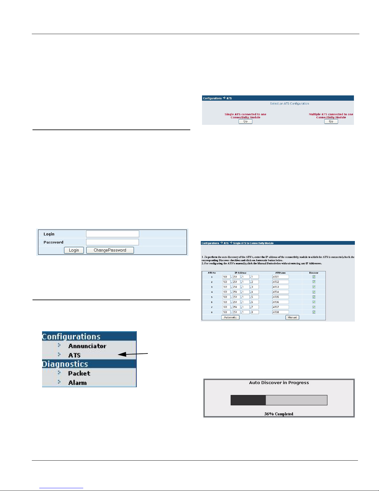
1 Login Screen
To login follow these steps:
1. Be sure that the computer is still connected to the Ethernet
switch (LAN).
2. Start the Internet Explorer browser on the computer.
3. In the address bar, type in the default address of the ATS
Remote Annunciator, then press Enter:
http://169.254.1.200
4. The ATS Remote Annunciator login page should appear.
Enter the default Login ( admin ) and Password ( ASCO )
from the label (see page 2) and click Login. See Figure 4.
Figure 4: Login screen
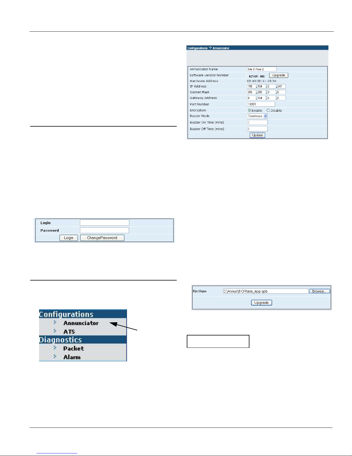
Figure 6: Configurations > Annunciator
2-1 Annunciator Name
Enter a name for the ATS Remote Annunciator.
Also write the name here _____________________________.
2-2 Software Upgrade
Write the software version here ________________________.
The firmware in the ATS Remote Annunciator can be
upgraded. Before upgrading, write down all configuration
settings of the ATS Remote Annuciator. These settings may
have to be made after the upgrade is completed.
1. Write down all configuration settings.
2. Click Browse, then click the file with .spb extension.
2 Annunciator Configuration
5. On the left pane, under Configurations, click Annunciator
to configure the ATS Remote Annunciator. See Figure
5.
click
3. Click Upgrade. See Figure 7.
Figure 7: Firmware update screen
NOTIC
Before updating the firmware, write down all
configuration settings.
Figure 5: Configurations > Annunciator
6. The Configurations > Annunciator screen appears. See
Figure 6. The configurations features are:
Annunciator name, software upgrade, IP address, subnet
mask, gateway address, port, encryption, buzzer mode.
381333-315 D ASCO Power Technologies Page 5
Page 6
Installation Manual ASCO 5350
2-3 IP Address, Subnet Mask, Gateway
1. The default IP address parameter is: 169.254.1.200. If the
ATS Remote Annunciator is on a LAN enter the
appropriate IP address of the LAN. The default subnet
mask parameter is: 255.255.0.0, and the gateway address is
0 0 0 0
2. Write the IP address here __________________________.
3. Write the Subnet Mask here ________________________.
4. Write the Gateway Address here ____________________.
2-4 Port
The TCP/IP port must match the port used in the Connectivity
Module (manual 381333-238). The default port is 10001 for
ASCO Bus; port 502 is typically used for Modbus.
Write the port number here ________________________.
2-5 Encryption
Click Enable to turn on encryption, or click Disable to turn it
off. The default configuration is Disable (off). The
Connectivity Module must also have encryption selected.
Write which option is selected here_____________________.
This feature is only available with encrypted-enabled CMs.
All other devices communicating with the CM must be able to
read the encrypted data.
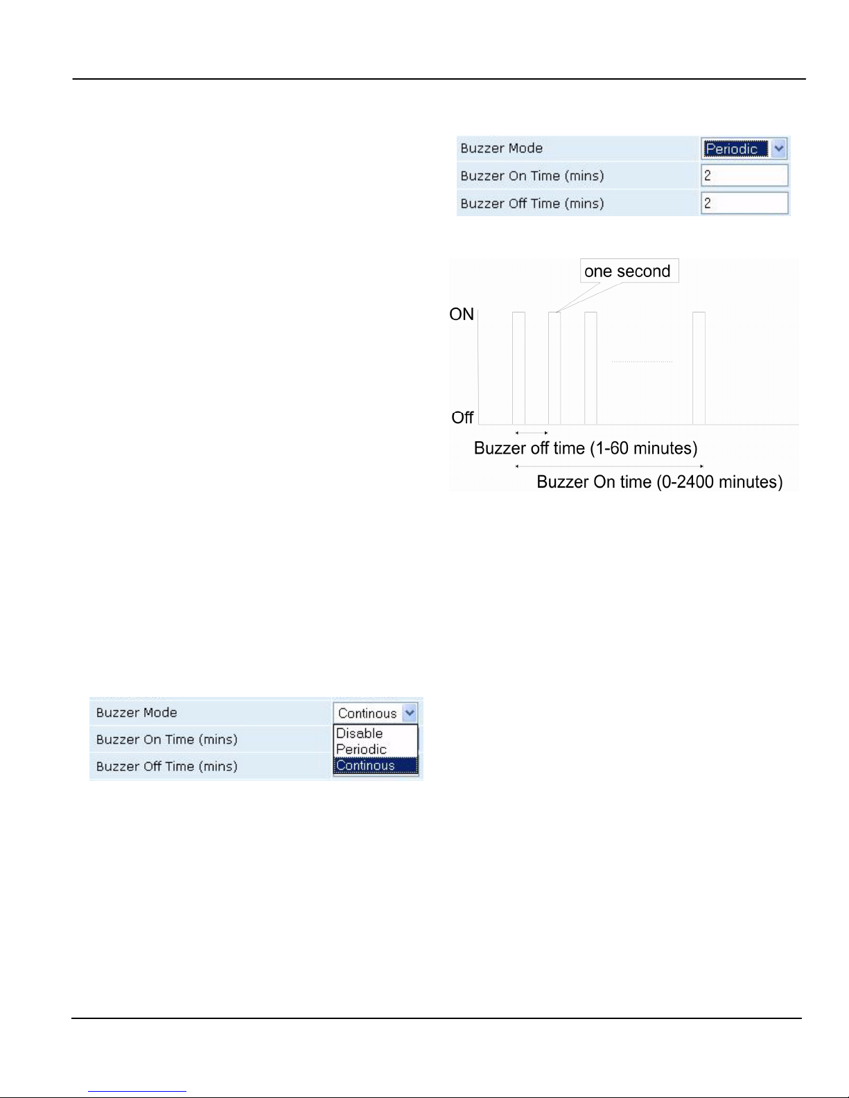
2-6 Audible Alarm (buzzer) Mode
Operation of the audible alarm and alarm relay (for external
buzzer) can be configured. In the Buzzer Mode list, click
Disable to turn it off (it will be inactive or silent even if an
alarm occurs). Click Periodic or Continuous to turn on the
audible alarm. The default setting is Continuous. See Figure
8. Write which option is selected here___________________.
2-7 Buzzer On Time (duration)
Figure 9: Audible Alarm (buzzer) ON - OFF Times
Figure 10: Buzzer interval & duration settings
Buzzer total ON time: it is the total time in which the buzzer
ON-OFF cycle will repeat in periodic mode from the time the
buzzer alarm is initiated. This time period needs to be entered
in the Buzzer On time text box. The acceptable range of
Buzzer ON time is between 0 to 2400 minutes, fractional
values are not acceptable. Buzzer silences only if alarm
condition ceases or Buzzer On time elapses, which ever
occurs early.
2-8 Buzzer Off Time (interval)
Figure 8: Audible Alarm (buzzer) Mode
The buzzer sounds in one-second pulses (not adjustable).
In the Continuous mode the pulsing buzzer sounds
continuously (on-off cycles). In the Periodic mode the
duration of the pulses and interval between pulses can be set
as follows:
Duration (On Time) 0-2400 minutes
Interval (Off Time) 1-60 minutes
See Figure 9. Figure 10 shows the duration and interval
settings.
Page 6 ASCO Power Technologies 381333-315 D
If the Buzzer on time is set to zero, the buzzer ON-OFF cycle
repats infinitely unless the alarm condition ceases or silence
alarm key is pressed.
The period of each buzzer ON-OFF cycle: It is the period after
which the Buzzer ON-OFF cycle repeats. This time period
needs to be entered in the Buzzer Off time text box. The
acceptable range of the period is between 1 to 60 minutes.
Fractional values are not acceptable. ON time in each of these
cycles is fixed at one second.
2-9 Click Update to Save Configurations !
Be sure to click UPDATE to save the configuration
settings and upload them to the ATS Remote
Annunciator.
Page 7
ASCO 5350 Installation Manual
ATS Configuration
The ATS Remote Annunciator must be configured for all the
ATSs that will be monitored and controlled. First log in. The
ATS Remote Annunciator sends HTML files to the client
computer. Internet Explorer interprets these HTML files,
formats them, and displays the pages to the user.
Single ATS connected to one Connectivity Module (CM)
- each ATS having its own Connectivity Module
Multiple ATS connected to one Connectivity Module
- all ATSs connected through a single Connectivity Module.
1 Login Screen
To login follow these steps:
1. Be sure that the computer is still connected to the Ethernet
switch (LAN).
2. Start the Internet Explorer browser on the computer.
3. In the address bar, type in the address of the ATS Remote
Annunciator, then press Enter:
http://169.254.1.200
4. The ATS Remote Annunciator login page should appear.
Enter the default Login ( admin ) and Password ( ASCO )
from the label (see page 2) and click Login. See Figure 11.
Figure 11: Login screen
2 ATS Configuration
Figure 13: Single or Multiple ATS configuration
2-1 Single ATS connected to one CM
You must know the IP address of the Connectivity Module
(CM) that corresponds with the ATS (and Power Manager, if
present) in the network. The ATS Remote Annunciator has an
auto discovery feature for a scenario in which one ATS is
connected to one CM. The user has to input the IP address
details of the CM to which the ATS is connected. After
performing the auto discovery, the information about the
discovered ATSs is displayed on the web interface. See Figure
14.
5. On the left pane, under Configurations, click ATS to
configure the ATSs that will be monitored. See Figure
12.
Figure 12: Configurations > ATS
6. The Configurations > ATS screen appears. See Figure 13.
Select either Single ATS or Multiple ATS based upon the
communication architecture of the ATSs and press the
corresponding Go button under the selection:
381333-315 D ASCO Power Technologies Page 7
click
Figure 14: Single ATS screen
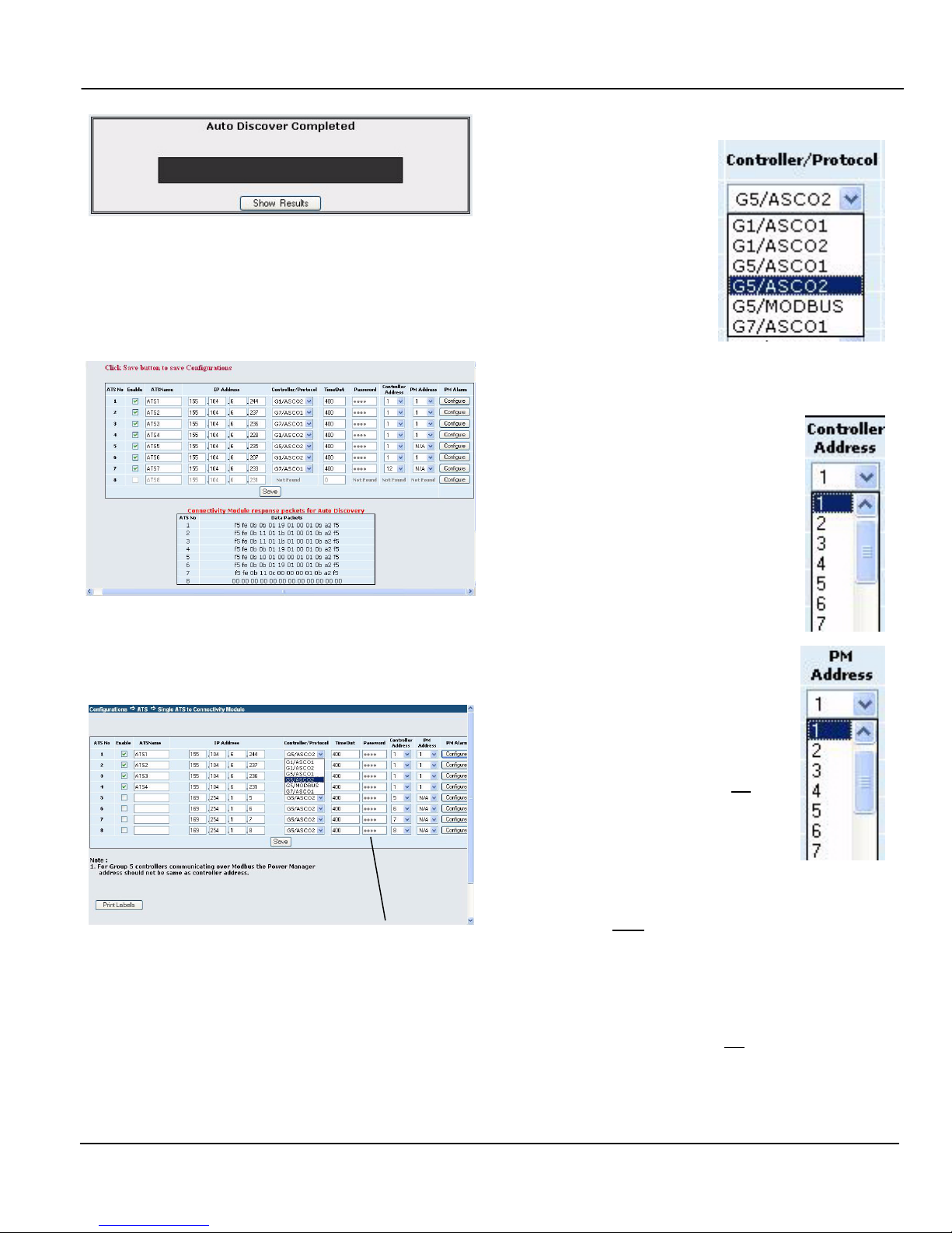
1. To perform the auto discovery of the ATSs, enter the IP
address of the CM to which the ATS is connected, select
the check boxes next to each ATS, then click Automatic.
See Figures 15 and 16.
Figure 15: Auto Discover in Process
Page 8
Installation Manual ASCO 5350
For 7000, 4000 Series ATSs select G5/ASCO1 or G5/ASCO2.
ASCO1 is for baud rate x9600
(ASCObus 1); ASCO2 is for
baud rate 19.2K (ASCObus 2).
For Modbus, see Notes below.
All ATSs must use the same
protocol. Refer to G5 User’s
Guide 381333-126.
Figure 16: Auto Discover Completed
For Series 300 ATSs select
G1/ASCO1 or G1/ASCO2. In
2. After auto discover is completed click Show Results.
Many of the ATS configurations are automatically filled.
Check the screen to be sure that all ATSs are found. If they
are, proceed to step 5. See Figure 17 for an example.
the Group 1 Controller,
visually determine the dash
number on the
microprocessor’s label (dash
number 9 and higher is
ASCObus 2). All ATSs must use the same protocol. For
ASCO 940 and 962 ATSs select G7/ASCO1.
Figure 19: Controller/Protocol manual selection
Figure 17: Auto Discover Results
3. To manually configure the ATSs click Manual on the
Single ATS screen (Figure 14). See Figure 18.
For 7000, 4000 Series enter Group 5 Controller password
Figure 18: Manual Configuration
Select the appropriate address that is set
in the ATS controller (G1, G5, or G7).
Figure 20: Controller Address
manual selection
If a Power Manager (PM) is used, the
address must be the same as the address set
in the corresponding ATS controller.
If G5/Modbus protocol is selected
(Figure 19), the PM Address should not be
the same as the address set in the Group 5
controller.
Figure 21: PM Address
manual selection
Modbus Notes: The password entered (Figure 22) for each
ATS must be the same as the password set in that ATS’s
Group 5 controller. The passwords can be all the same or there
can be 8 different passwords depending upon the passwords
set in the G5 controllers. Refer to User’s Guide 381333-126.
4. Click Enable, enter the ATS Name, and the IP Address.
On the Controller/ Protocol list, Controller Address, and
PM Address, select the appropriate settings. See Figures
19, 20, 21.
Page 8 ASCO Power Technologies 381333-315 D
If the Group 5 password is not entered on the Configuration
screen (Figure 18), the ATS Remote Annunciator will only
show the status of the ATS. It will not transfer the load. No
warning or indication of the reason will be shown.
Page 9
ASCO 5350 Installation Manual
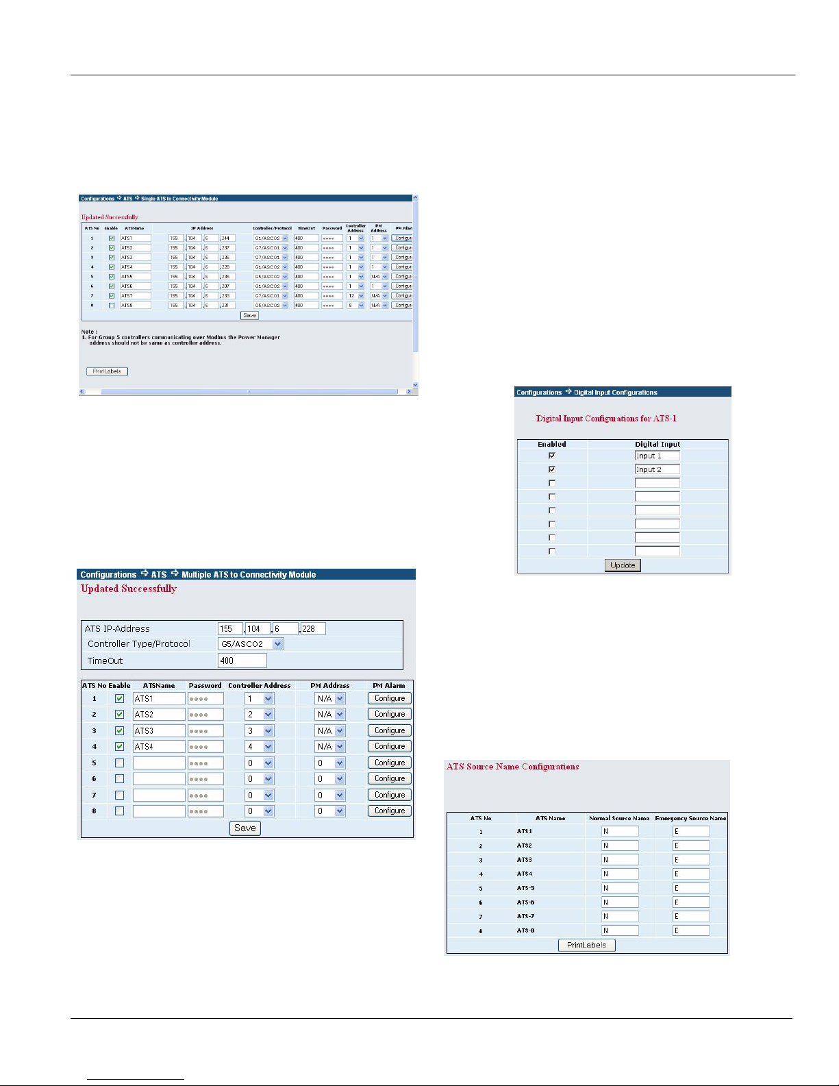
5. When all ATS configurations are made, click Save to
upload the configuration to the ATS Remote Annunciator.
An Uploaded Successfully screen should appear. See
Figure 22. The ATS Remote Annunciator should now be
monitoring the ATSs (observe the status lights).
Figure 22: Updated Successfully screen
2-3 Configuring Power Manager Alarms
If a Power Manager (PM) is provided with an ATS, the PM’s
eight Status Inputs can be configured to signal an alarm at the
ATS Remote Annunciator. At the PM, the Status Input must
be set to ACTV (on). Refer to PM manual 381333-199.
1. Be sure that a PM Address has been set (Figure 21). Then
click the Configure button (Figure 23) next to PM Address
2. The first row (top) is for PM Status Input 1. Click Enabled.
3. Next, enter a name in the Digital Input column, if desired.
4. Repeat steps 2 and 3 for each PM Status Input that is
ACTV (on). The second row is Status Input 2, etc. See
Figure 24.
5. Click the Update button to save these configurations.
6. Click the Save button to save all configurations to the ATS
Remote Annunciator. See Figure 22.
2-2 Multiple ATSs connected to one CM
In this mode, there is a single Connectivity Module for
multiple ATSs (that are daisy chained together). Therefore the
configuration is for one IP address (as assigned by the network
architect or administrator). Refer to the Figure 23.
Figure 23: Multiple ATSs connected to one CM
Figure 24: PM Status Input configuration
2-4 Print label
After the configurations are done and saved, you can print
custom labels for the ATS Remote Annunciator (Figure 1 on
page 2). A printer must be connected to the laptop computer
that is used for setting the configurations. Click the Print
Labels button at the bottom of the screen. See Figures 22 and
25.
1. Perform step 4 on page 8 (Figures 19, 20, 21). All ATSs
must be of the same series (same controller).
2. Click the Save button to save the configuration.
381333-315 D ASCO Power Technologies Page 9
Figure 25: Print labels screen
Page 10
Installation Manual ASCO 5350
Diagnostics
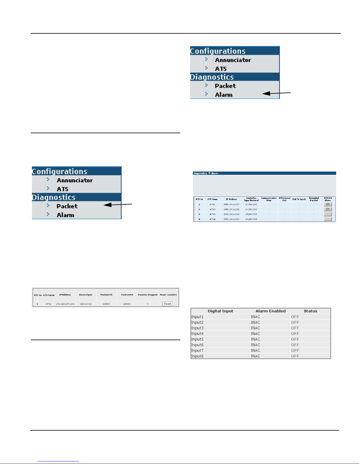
Diagnostics can be used to check communication packets and
to check for ATS alarms (to determine why the Alarm light is
on).
If necessary, reconnect the laptop computer that was used to
configure the ATS Remote Annunciator. Then log in as
described on page 5.
Figure 28: Diagnostics > Packet
click
1 Packets
On the left pane, under Diagnostics, click Packet to check
send and receive packets from Connectivity Modules to the
ATS Remote Annunciator. See Figure 26.
click
Figure 26: Diagnostics > Packet
The Diagnostics > Packet screen shows all ATSs (up to 8). It
lists the ATS No., ATS Name, IP Address, DeviceType
(controller/protocol), Packets Sent (TX), Packets Received
(RX), and Packets Dropped. The number of packets dropped
indicates the communication quality (lower is better). To reset
the counters, click the Reset button. See Figure 27.
The Diagnostics > Alarm screen shows if there any of these
ATS alarms: Communication Error, ATS Locked Out
(7ADTS, 4ADTS), Failure to Synchronize (7ACTS, 4ACTS),
and Extended Parallel (7ACTS, 4ACTS). See Figure 29.
Based upon which alarm has occurred, specific action can be
taken. See Troubleshooting.
Figure 29: Diagnostics > Alarm screen
If a Power Manger (PM) has been configured for Status Input
alarms, click the ON button to see their status. For each
Digital Input, the Alarm Enabled will show INAC for not
enabled or ACTV for enabled. ACTV means the ATS Remote
Annunciator is configured to accept a PM input alarm. In the
Status column, OFF means there is no alarm; ON means there
is an alarm (status input). See Figure 30.
Figure 27: Diagnostics > Packet screen
2 Alarm
On the left pane, under Diagnostics, click Alarm to see the
status of all ATS alarms that are configured. See Figure 28.
Page 10 ASCO Power Technologies 381333-315 D
Figure 30: PM Status Input alarm status
If an audible alarm is sounding at the ATS Remote
Annunciator, it can be silenced (see User’s Guide 381333-
314). But the alarm will not reset until it is corrected at the
source (PM status input).
Page 11

ASCO 5350 Installation Manual
Troubleshooting
Number Symptom Probable Cause Recommended Action
1 Power ON light is off
Lamp test button does not
work.
2
3 The power ON light is blinking.
4
Alarm silence does not
respond.
There is no response on any
key.
Transfer button does not work
(load transfer does not occur).
The DC or AC power source is
inadequate or off.
The Control switch is locked. Insert Control key and turn it to unlock.
The unit keeps on resetting due
to watchdog-reset possibly due
to corruption of software.
Button not held long enough.
ATS Annunciator could have
changed to default settings.
Restore the DC or AC power supply.
Check the terminals, fuse, circuit breaker.
Refer to Installation Manual 381333-315.
Try to reprogram the unit with the latest
software.
Contact ASCO Services for replacement.
800-800-ASCO or
[email protected]
Hold the button for at least 5 seconds
until you hear a beep..
Refer to Installation Manual 381333-315.
Use the configuration details entered on
page 2; reconfigure the ATS Annunciator.
The password must be configured.
See Modbus Notes on page 8.
Refer to Installation Manual 381333-315.
Check the Ethernet connections:
ATS Annunciator to the LAN and
Power Manager to the LAN.
Refer to Installation Manual 381333-315.
Verify that the protocol on both devices is
the same.
Contact ASCO Services for replacement.
800-800-ASCO or
[email protected]
Contact ASCO Services for replacement.
800-800-ASCO or
[email protected]
5 Buzzer is beeping continuously.
Communication alarm occurs
6
7
8
but all configurations are
correct.
A light does not come on when
a corresponding button is
pressed.
A light does not come on when
the lamp test button is pressed.
Password not set
Communication with the Power
Manager may have stopped.
Communication protocol may not
the same as that of the Power
Manager (if present).
ATS Annunciator is
not functioning properly.
ATS Annunciator is
not functioning properly.
381333-315 D ASCO Power Technologies Page 11
Page 12

Index ASCO 5350
Index
A
address
controller, 8
IP, 2, 4, 5, 6
alarm buzzer, 3, 8, 10
alarm light, relay
alarm silence button, refer to
User’s Guide 381333-314
annunciator, configuration, 14
ATS configuration, 7
ATS controller, 1, 8
ATS name, ATS no., 7, 8, 9
auto discovery, 8
B
bezel release, 2
buttons, refer to
User’s Guide 381333-314
buzzer configuration, 3, 6
bypass (cancel) transfer time delay,
refer to User’s Guide 381333-314
C
cable, communication, 2, 3,
wiring diagram 834969
change password, 4
communication architecture, 3
communication check, 4
communication wiring, 3,
wiring diagram 834969
Configurations, ATS configuration, 7
ATS Remote Annunciator, 5
connections, 3
Connectivity Module (CM) 5150,
3, 11, refer to Installation
Manual 381333-238
control key switch, 4, 11
controller, ATS, 1, 8
controller address, protocol, 8
D
diagnostics, 10
digital input, 10
discover, 11
F
factory default information, 2
firmware update, 5
functional test, 4
G
gateway address, 2, 4, 6
Group 5 controller, 8
H
HELP, 800-800-2726 (ASCO),
[email protected]
I
initial checks, 4
installation, 3
internal buzzer and alarm relay, 3
Internet Protocol, 7
IP address, 2, 4, 5, 6
K
key switch, Control, 11, refer to
User’s Guide 381333-314
L
labels, 2, 9
lamp test button, 4, 11
lights, 4, 11, refer to
User’s Guide 381333-314
login, 2, 4, 5
M
mounting, 3
multiple ATSs connected to single CM,
9
O
operation, refer to
User’s Guide 381333-314
P
packet, 10
password, 2, 4, 8, 11
port number
Power Manager (PM), 8
power on light, 4, 11
print label, 2, 9
R
ratings, 2
reboot, reset, refer to
User’s Guide 381333-314
S
save configuration, 9
select an ATS configuration, 7
single ATS connected to single CM, 5,
7
specifications, 2
software version, 5
subnet mask, 2, 4, 6
T
test, lamp button, 4, 11
time delay, transfer, bypass (cancel),
refer User’s Guide 381333-314
Transfer button, 16
troubleshooting, 11
U
update, save configuration, 6
update, firmware, 9
controller password, 8
custom ATS labels, 2
Page 12 Copyright 2014 ASCO Power Technologies. All rights reserved. 381333-315 D
N
name, 5
 Loading...