

Page 1
Ascon Tecnologic - KX6 - ENGINEERING MANUAL - PAG. 1
KX6
CONTROLLER WITH
SERVOMOTOR DRIVE OUTPUT
Engineering Manual
Code : ISTR-MKX6-ENG00 - Vr. 0.0 (ENG)
Ascon Tecnologic S.r.l.
Viale Indipendenza 56, 27029 Vigevano (PV) - ITALY
Tel.: +39 0381 69871/FAX: +39 0381 698730
www.ascontecnologic.com
e-mail: [email protected]
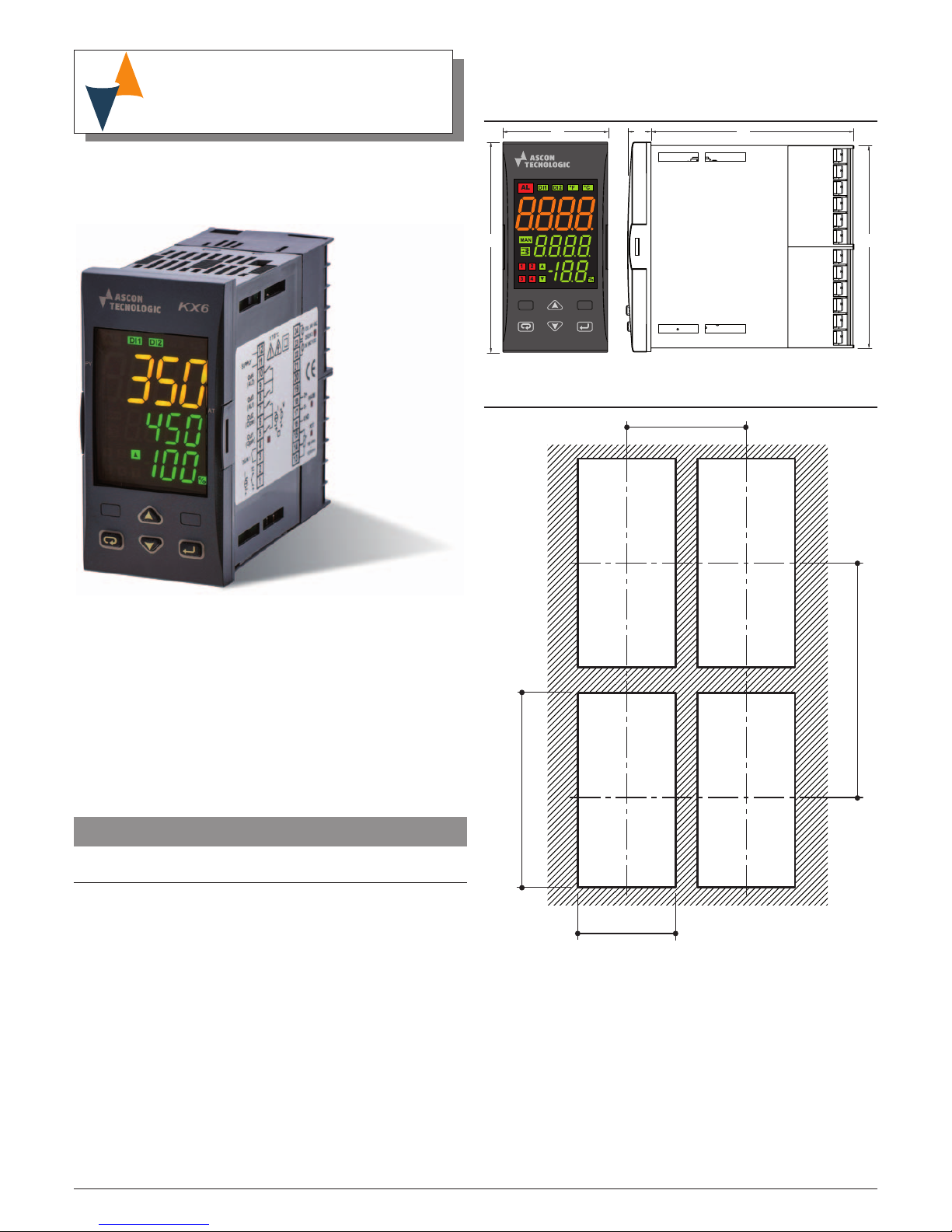
1 OUTLINE DIMENSIONS (mm)
1.1 Mounting requirements
This instrument is intended for permanent installation, for
indoor use only, in an electrical panel which encloses the
rear housing, exposed terminals and wiring on the back.
Select a mounting location having the following characteristics:
1. It should be easily accessible;
2. There is minimum vibrations and no impact;
3. There are no corrosive gases;
4. There are no water or other fluids (i.e. condensation);
5. The ambient temperature is in accordance with the
operative temperature (0... 50°C);
6. The relative humidity is in accordance with the instrument
specifications (20... 85%);
The instrument can be mounted on panel with a maximum
thickness of 15 mm.
When the maximum front protection (IP65) is desired, the
optional gasket must be mounted.
1.2 Dimensions
48 8911
96
89
1.3 Panel cutout
65 mm min.
45
+0.6
mm
89
+0.8
mm
113 mm min.
Page 2
Ascon Tecnologic - KX6 - ENGINEERING MANUAL - PAG. 2
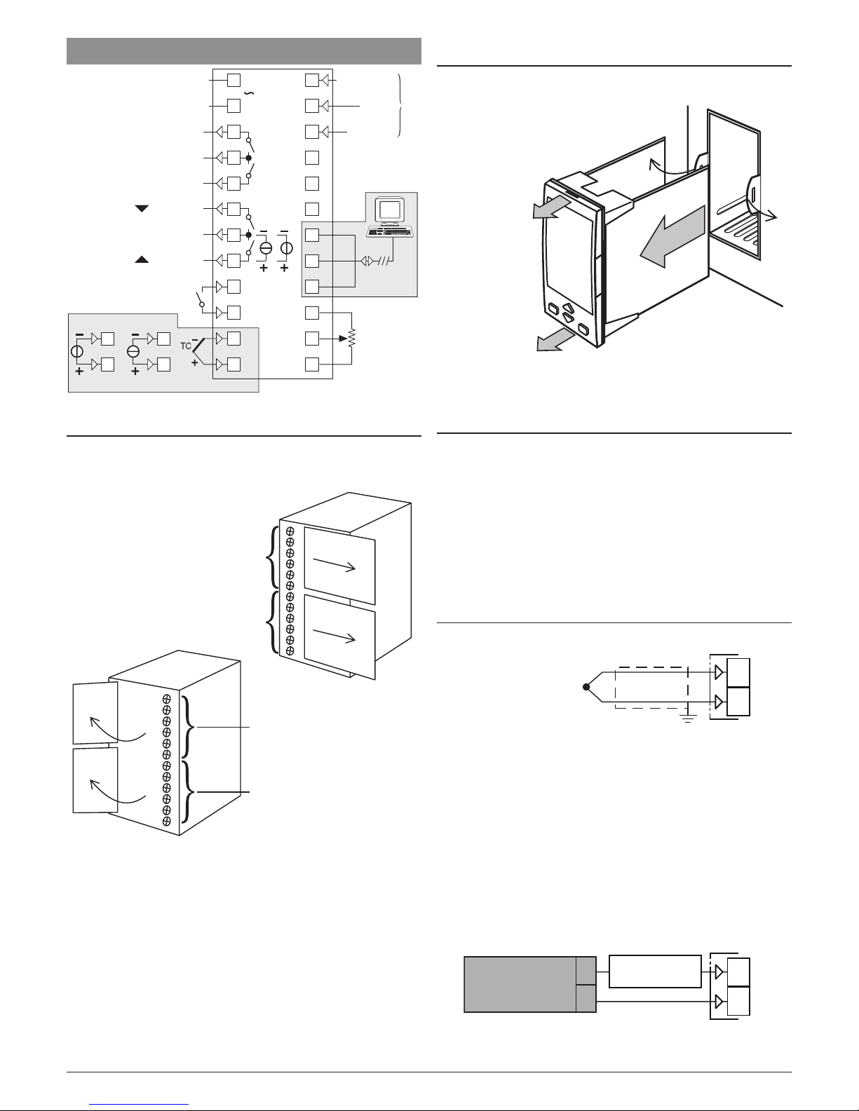
2 CONNECTION DIAGRAM
Thermocouple
DI1
Out1 (2A)
Out2 (2A)
Out3 (2A)
Out4 (2A)
Analogue Input
RS485
mA
Neutral
100... 240 VAC
100... 240 VAC
24 VAC/VDC
C
NO
NO
C
Phase
1
2
V/mV
1
2
2
1
4
3
6
5
8
7
10
9
12
11
NO
14
13
16
15
18
17
20
19
22
21
24
23
NO
C
IN1
IN2
GND
D-
D+
DI2
Potentiometer
100Ω... 10 kΩ
mA (600Ω max.)
V (500Ω max.)
2.1 Terminal covers
The controller terminals are protected with plastic covers. In
order to make the connections, move the covers as shown in
the illustrations.
Te rminals
1... 6
Te rminals
7... 12
Te rminals
19... 24
Te rminals
9... 24
2.2 Controller unplugging
The controller can be extracted from its housing (without
removing the cabling).
1A
2
1A
1
1
2 Extract the controller
module from the
external housing
1, 1A Pulling the controller from the upper
and lower sides, carefully open
in sequence the 2 retainers
To re-insert the controller in its housing, reverse the
extraction procedure.
2.3 General notes about wiring
1. Do not run input wires together with power cables.
2. External components (like zener barriers, etc.) connected
between sensor and input terminals may cause errors in
measurement due to excessive and/or not balanced line
resistance or possible leakage currents.
3. When a shielded cable is used, it should be connected at
one point only.
4. Pay attention to the line resistance; a high line resistance
may cause measurement errors.
2.4 Inputs
2.4.1 Thermocouple Input
1
2
+
_
Continuity detection current: 250 nA.
Cold junction: automatic compensation between 0... 50°C.
Cold junction thermal drift: 0.1°C/°C after a warm-up of
20 minutes.
Input impedance: > 1 MΩ.
Calibration: According to EN 60584-1.
Note: For TC wiring use proper compensating cable
preferable shielded.
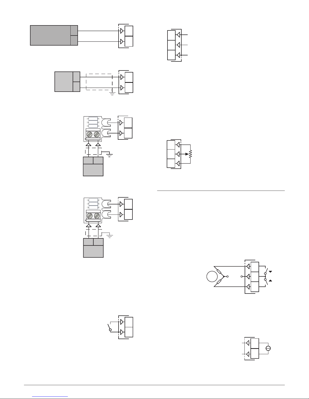
2.4.2 mA Input
0/4... 20 mA input wiring for passive transmitter
using an external pws
+
_
+
_
1
2
0/4...20 mA
Passive
transmitter
_
External
PWS
+
Input impedance: < 50 Ω.
Page 3
Ascon Tecnologic - KX6 - ENGINEERING MANUAL - PAG. 3
0/4... 20 mA input wiring for active transmitter
0/4...20 mA
Active
transmitter
+
_
+
_
1
2
Input impedance: < 50 Ω.
2.4.3 mV input
mV
+
-
+
_
1
2
Input impedance: > 1 MΩ.
2.4.4 0... 5 V input
12
0... 5V
+
-
+
_
1
2
AD ADPINMV-KX-V5
Adapter
Input impedance: > 4 kΩ.
2.4.5 0... 10 V input
12
+
-
1
2
AP ADPINMV-KX-V10
Adapter
0... 10V
+
_
Input impedance: > 10 kΩ.
2.4.6 Logic Inputs
Safety notes:
– Do not run logic input wiring together with power cables;
– The instrument needs 150 ms to recognize a contact
status variation;
Logic input 1 - Driven by dry contact
3
4
Digital
input 1
Maximum contact resistance: 100Ω.
Contact rating: 10 V, 6 mA;
Note: Logic input 1 is NOT isolated by the measuring input.
A double or reinforced isolation between logic input 1
and power line must be assured by the external
elements.
Logic input 2 - Driven by 24 VAC/DC or 100... 240 VAC
22
23
24
Digital input 2
100... 240 VAC
Common
24 VAC/DC
Notes: 1. The isolated input DI2 must be used in one of the
modes determined by the link:
• High-level input (110... 220 VAC);
• Low level input (24 VDC/VAC).
2. Logic input 2 is isolated by the measuring input.
A double or reinforced isolation between DI
2 and
power line is ensured by the instrument.
2.4.7 Potentiometer input
Safety notes:
– Do not run potentiometer input wiring together with power
cables.
Potentiometer
100 Ω... 10 kΩ
Input 2
13
14
15
Potentiometer range: From 100W to 10 kW.
2.5 Outputs
Safety notes:
– To avoid electrical shocks, connect power line at last.
– For supply connections use No. 16 AWG or larger wires
rated for at last 75°C.
– Use copper conductors only.
m
Before connecting the output actuators,
we recommend to configure the parameters to suit
your application (e.g.: input type, Control strategy,
alarms, etc.).
2.5.1 Servomotor output
Power
Supply
Close
Open
M
~
5
6
7
OP1
OP2
Contact rating: •4A/250Vcosj =1;
•2A/250Vcosj =0.4.
Operation: 1 x 10⁵.
2.5.2 Analogue Ouput 1 (OP1)
Current Analogue Output
mA
-
5
6
+
mA output: 0/4... 20 mA, galvanically isolated.
Maximum Load Impedance: 500Ω.
Page 4
Ascon Tecnologic - KX6 - ENGINEERING MANUAL - PAG. 4
Voltage Analogue Output
V
-
5
6
+
Voltahge output: 0/2... 10 V, galvanically isolated.
Minimum Load Impedance: 500Ω.
2.5.3 Alarm 1 and Alarm 2 output
C
AI2
AI1
9
10
8
Load 2
Load 1
VAC
Contact rating: •2A/250Vcosj = 1;
•1A/250Vcosj = 0.4.
Operation: 1 x 10⁵.
2.6 Serial Interface
RS-485
D -
D +
GND
17
18
16
D -
D +
GND
D -
D +
GND
D -
D +
GND
Interface type: Isolated (50 V) RS-485;
Voltage levels: According to EIA standard;
Protocol type: MODBUS RTU;
Byte format: 8 bit with no parity;
Stop bit: 1 (one);
Baud rate:
Programmable between 1200... 38400 baud;
Address: Programmable between 1... 255.
Notes: 1. RS-485 interface allows to connect up to 30
devices with one remote master unit.
2. The cable length must not exceed 1.5 km at
9600 baud.
2.7 Power Supply
Power
Supply
11
12
Supply Voltage: 100... 240 VAC (-15... +10%).
Notes: 1. Before connecting the instrument to the power
line, make sure that line voltage is equal to the
voltage shown on the identification label;
2. The polarity of the power supply has no importance;
3. The power supply input is NOT fuse protected.
Please, provide a T type 1A, 250 V fuse externally.
4. When the instrument is powered by the A01 key,
the outputs are NOT supplied and the instrument
can show the “ouLd” (Out 4 Overload) indication.
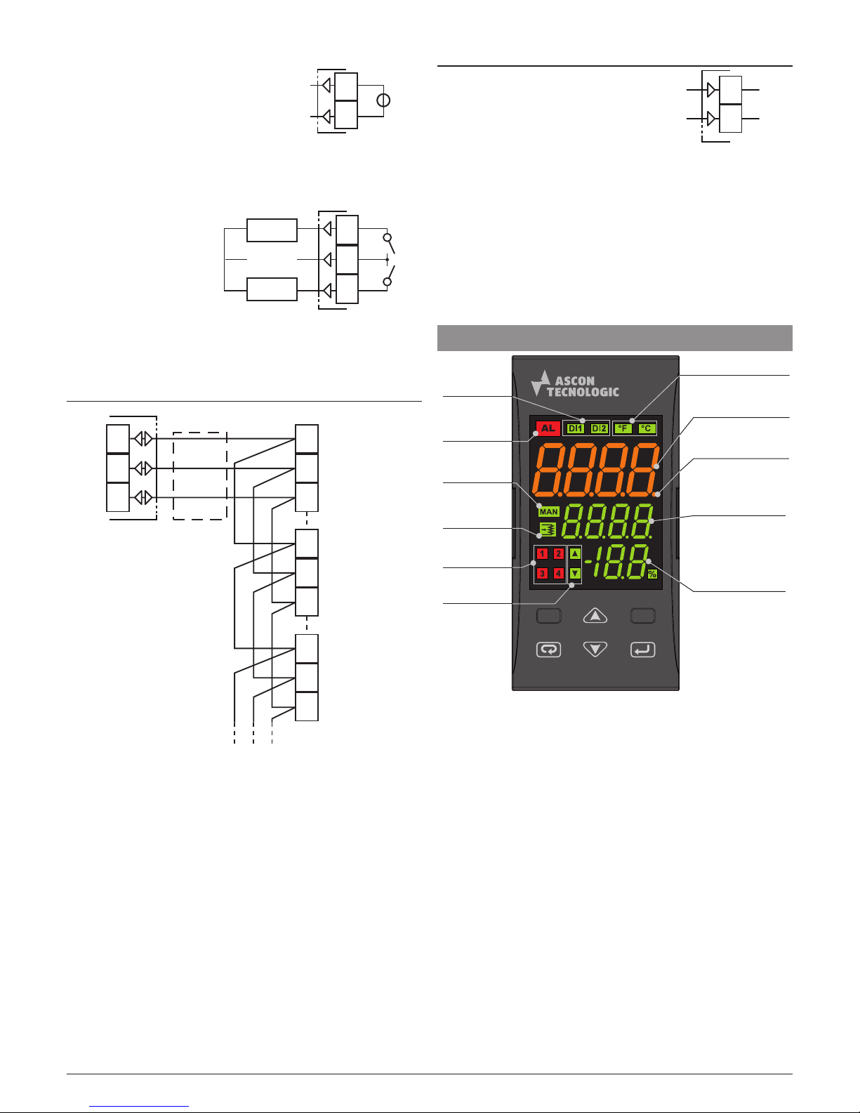
3 PANEL DESCRIPTION
Process Value
(in eng. units)
Autotune
in progress
(flashing)
Programmable
display
(usually shows
the Set Point)
Output
LEDs
Manual
mode
Alarm
active
Eng. Unit
(°C/°F)
Potentiometer (*)
Digital
inputs ON
Valve
Open/Close
Valve position
(measured or
theoretical)
* Lit when the instrument is using the potentiometer;
flashes when a potentiomter malfunction is detected.
Page 5
Ascon Tecnologic - KX6 - ENGINEERING MANUAL - PAG. 5
4 TECHNICAL CHARACTERISTICS
Case:
Plastic, self-extinguishing degree: V-0 according to UL 94;
Front protection: IP65 (when the optional panel gasket is
mounted) for indoor locations according to EN 60070-1;
Terminals protection: IP20 according to EN 60070-1;
Installation: Panel mounting;
Terminal block:
24 M3 screw terminals for cables of
0.25... 2.5 mm2 (AWG22... AWG14) with connection diagram;
Dimensions: 48 x 96, depth 89,15 mm.
Panel cutout: 45(+0.6) x 89(+0.6) mm [1.78(+0.023) x 3.5(+0.023) in.]
Weight: 160 g max..
Power supply: 100... 240 VAC (-15... +10% of the nominal
value);
Power consumption: 5 VA max.;
Insulation voltage: 3000 V rms according to EN 61010-1;
Display updating time: 500 ms;
Sampling time: 130 ms;
Resolution: 30000 counts;
Total Accuracy: ±0.5% F.S.V. ±1 digit @ 25°C of room
temperature;
Temperature drift: It is part of the global accuracy;
Operating temperature: 0... 50°C (32... 122°F);
Storage temperature: -30... +70°C (-22... +158°F);
Humidity: 20... 85% RH, not condensing.
Electromagnetic compatibility and safety requirements
Compliance:
• EMC Directive (EN 61326-1),
• Safety Directive (EN 61010-1);
Installation category: II;
Pollution category: 2.
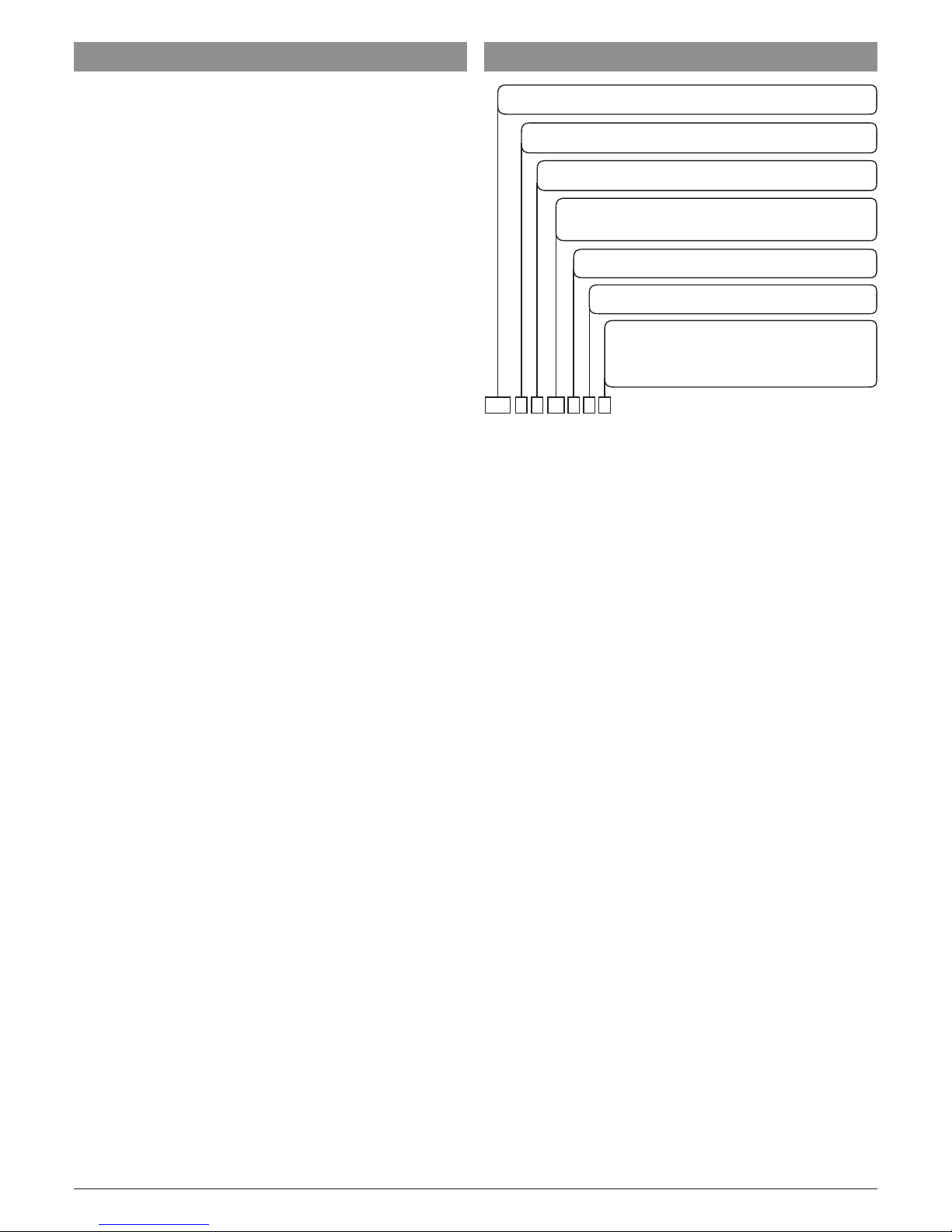
5 HOW TO ORDER
Power supply
H = 100... 240 VAC
Analogue input + digital input DI1 (standard)
B = J, K, R, S, T, mA, mV (*)
Output 3
R = Relay SPST NO 2 A (resistive load)
Output 4
R = Relay SPST NO 2 A (resistive load)
Options (the TTL Modbus port is always present)
- = Not available
C =
Potentiometer input + Digital Input 2 + RS 485 Modbus
P = Potentiometer input + Digital Input 2
S = RS 485 Modbus
Model
KX6 - = Valve Controller
Output 1 + Output 2
I- = Output 1: 0/4... 20 mA, 0/2... 10 V; Output 2: Not available
MM = Output 1 + Output 2: Relays for servomotor SPST NO 2 A
KX6- HB RR
* It is possible to obtain a 0... 10 V or 0... 5 V input,
ordering the following part no., respectively:
• AP ADPINMV-KX-V10 (for 0... 10 V);
• AD ADPINMV-KX-V5 (for 0... 5 V).
Page 6

Ascon Tecnologic - KX6 - ENGINEERING MANUAL - PAG. 6
6 CONFIGURATION PROCEDURE
6.1 Introduction
When the instrument is powered, it starts immediately to work
according to the parameters values loaded in its memory.
The instrument behaviour and its performance are governed
by the value of the stored parameters.
At the first start up the instrument will use a “default”
parameter set (factory parameter set); this set is a generic
one (e.g. a TC J input is programmed).
m
Before connecting the output actuators,
we recommend to configure the parameters to suit
your application (e.g.: input type, Control strategy,
alarms, etc.).
m
Do not change the [5] Unit (Engineering Unit) value
during process control as the set point inserted by
the user (thresholds, limits etc.) are not automatically
rescaled by the instrument.
To change these parameters you need to enter the
“Configuration mode”.
6.2 Instrument behaviour at Power ON
At power ON the instrument can start in one of the following
mode depending on its configuration:
Auto mode.
– The upper display will show the measured value;
– The meddle display will show the Set point value;
– The lower display will show the valve position (measured
or theoretical according to the control strategy selected).
– The instrument is performing the standard PID control with
servo-motor drive output.
Manual mode (oPLo).
– The upper display shows the measured value;
– The middle display shows the power output [preceded by H
(for heating) or C (for cooling)]. The MAN LED is lit;
– The lower display will show the valve position (measured
or theoretical according to the
selected control
).
– The instrument does not perform Automatic control;
– The control output can be manually modified by and
buttons.
Stand by mode (St.bY).
– The upper display will show the measured value;
– The middle display will show alternately the set point value
and the message St.bY or od;
– The lower display will show the valve position (measured
or theoretical according to the control strategy selected).
– The instrument does not perform any control (the Out 2
[close] is ever ON);
– The instrument is working as an indicator.
6.3 Configuration modes
6.3.1 How to enter the “Configuration modes”
The configuration mode allows to take advantage of all
instrument features.
The instrument have one complete parameter set.
We call this set “configuration parameter set” (or
“configuration parameters”).
The access to the configuration parameters is
protected by a
password.
Note: The instrument will show only the parameters consistent
with the specific hardware and in accordance with the
value assigned to the previous parameters
(e.g.: if you set an Alarm as “not used” the instrument
will mask all other parameters related to this Alarm).
6.3.2 Complete configuration procedure
The configuration parameters are collected in various
groups. Every group defines all parameters related with a
specific function (e.g.: control, alarms, output functions).
1. Push the button for more than 5 seconds. The upper
display will show PASS while the middle display will show 0.
2. Using
and
buttons set the programmed password.
Notes: 1. The factory default password for configuration
parameters is equal to 30.
2. During parameter modification the instrument
continue to perform the control.
In certain conditions, when a configuration change
can produce a heavy bump to the process, it is
advisable to temporarily stop the controller from
controlling during the programming procedure
(control output will be OFF).
A password equal to 2000 + the programmed
value (e.g. 2000 + 30 = 2030).
The control will restart automatically when the
configuration procedure will be manually closed.
3. Push the button.
If the password is correct the display will show the
acronym of the first parameter group preceded by
the symbol: ].
In other words the upper display shows:
]inp
(group of the Input parameters).
The instrument is in configuration mode.
6.3.3 How to exit the “Configuration mode”
Push button for more than 5 seconds, the instrument will
come back to the “standard display”.
6.4 Keyboard functions during
parameter changing
A short press allows to exit from the current parameter
group and select a new parameter group.
A long press allows you to close the configuration
parameter procedure (the instrument will come back
to the “standard display”).
When the upper display is showing a group and the
middle display is blank, this key allows to enter in the
selected group.
When the upper display is showing a parameter and
the middle display is showing its value, this key allows
to store the selected value for the current parameter
and access the next parameter within the same group.
Allows to increase the value of the selected parameter.
Allows to decrease the value of the selected parameter.
+ These two keys allow to return to the previous
group. Proceed as follows:
Push the button and maintaining the pressure,
then push the button; release both the buttons.
Note: The group selection is cyclic as well as the selection
of the parameters in a group.
Page 7

Ascon Tecnologic - KX6 - ENGINEERING MANUAL - PAG. 7
6.5 Factory reset - Default parameters
loading procedure
Sometime, e.g. when you re-configure an instrument
previously used for other works or from other people or when
you have made too many errors during configuration and
you decided to re-configure the instrument, it is possible to
restore the factory configuration.
This action allows to put the instrument in a defined condition
(the same it was at the first power ON).
The default data are those typical values loaded in the
instrument prior to ship it from factory.
To load the factory default parameter set, proceed as follows:
1. Press the button for more than 5 seconds. The upper
display will show PASS while the middle display shows 0;
2. Using and buttons set the value -481;
3. Push button;
4. The instrument will turn OFF all LEDs for a few seconds,
then the upper display will show dFLt (default) and then
all LEDs are turned ON for 2 seconds. At this point the
instrument restarts as for a new power ON.
The procedure is complete.
Note: The complete list of the default parameters is available
in Appendix A.
6.6 OEM Reset/
OEM Default
Parameters Set
In addition to the “Factory default” these instruments allow
the OEM to store his own default parameter set. In this way
if an end-user tampers the parameter values, the after sales
support of the OEM has a fast and easy way to reset the
machine and return to the proprietary parameter set.
6.6.1 Storing the OEM default parameter set
Once the OEM has configured his own paratameter set and is
returned to the “Standard display”, in order store these values
as a “Proprietary default” the OEM must proceed as follows:
1. Press the button for more than 5 seconds. The upper
display will show PASS while the middle display shows 0;
2. Using and buttons set the value -682;
3. Push button;
4. The instrument shows LoAd on the upper display in order
to highlight that the memorization has been made, then
returns to the
“Standard display”
mode.
6.6.2 Loading the OEM default parameter set
1. Press the button for more than 5 seconds. The upper
display will show PASS while the middle display shows 0;
2. Using and buttons set the value -581;
3. Push button;
4. The instrument turns ON all the LEDs for a few seconds,
then returns to the
“Standard display”
mode.
Notes: 1. If the instrument does not turn ON all the
LEDs for at least 2 seconds, it means that the
password inserted was incorrect and the OEM
parameter set has NOT been loaded.
2. Using the serial link it is always possible to send to
the address 13H the corretct password in order to
obtain the desired action (-481 for the Factory set,
-581 for OEM set or -682 to store the OEM set).
6.7 Configuring all Parameters
In the following pages we will describe all the parameters of
the instrument. However, the instrument will only show the
parameters applicable to its hardware options in accordance
with the specific instrument configuration (i.e. setting AL1t
[Alarm 1 type] to nonE [not used], all parameters related to
alarm 1 will be skipped).
]inP Group - Main input configuration
[1] SEnS - Input type
Available: Always.
Range: J TC J (-50... +1000°C/-58... +1832°F);
crAL TC K (-50... +1370°C/-58... +2498°F);
S TC S (-50... 1760°C/-58... +3200°F);
r TC R (-50... +1760°C/-58... +3200);
t TC T (-70... +400°C/-94... +752°F);
0.20 0... 20 mA linear;
4.20 4... 20 mA linear;
0.60 0... 60 mV linear (see note 3);
12.60 12... 60 mV Linear (see note 3).
Notes: 1. When a TC input is selected and a decimal figure
is programmed (see the next parameter) the max.
displayed value becomes 999.9°C or 999.9°F.
2. Every change of the SEnS parameter setting
will force the [2] dP = 0 and it will change all
parameters related with dP (e.g. set points,
proportional band, etc.);
3. In order to obtain a 0... 5 V or a 0... 10 V input,
select 0... 60 mV and connect the adapter:
- 0... 5 V = AD ADPINMV-KX-V5;
- 0... 10 V = AP ADPINMV-KX-V10;
[2] dP - Decimal point position
Available: Always.
Range: When [1] SenS = Linear input: from 0 to 3.
When [1] SenS different from linear input: 0 or 1.
Note: Every change of the dP parameter setting will produce
a change of the parameters related with it (e.g.: set
points, proportional band, etc.).
[3] SSc - Initial scale read-out for linear inputs
Available: When a linear input is selected by [1] SenS.
Range: -1999... 9999.
Notes: 1. SSc allows the scaling of the analogue input to
set the read-out value shown when the instrument
detect the minimum measurable value.
The instrument will show a measured value up to
5% less then SSc value and than it will show an
underrange error.
2. It is possible to set a initial scale read-out higher
then the full scale read-out in order to obtain a
reverse read-out scaling. For example:
0 mA = 0 mBar and 20 mA = -1000 mBar (vacuum).
[4] FSc - Full scale read-out for linear input
Available: When a linear input is selected by [1] SenS.
Range: -1999... 9999
Notes: 1. Fsc allows the scaling of the analogue input to set
the read-out value shown when the instrument
detect the maximum measurable value.
The instrument will show a measured value up to
5% higher than [4] FSc value and then it will show
an overrange error.
2. It is possible to set a full scale read-out lower
Page 8

Ascon Tecnologic - KX6 - ENGINEERING MANUAL - PAG. 8
than the initial scale read-out in order to obtain a
reverse read-out scaling. For example:
0 mA = 0 mBar and 20 mA = -1000 mBar (vacuum).
[5] unit - Engineering unit
Available: When a temperature sensor is selected by
[1] SenS parameter.
Range: °c Centigrade;
°F Fahrenheit.
m
The instrument does not rescale the temperature
values inserted by the user (thresholds, limits etc.).
[6] FiL - Digital filter on the measured value
Available: Always.
Range: oFF (No filter)
0.1... 20.0 s.
Note: This is a first order digital filter applied on the measured
value. For this reason it will affect the measured value
but also the control action and the alarms behaviour.
[7] inE -
Selection of the Sensor Out of Range type
that will enable the safety output value
Available: Always.
Range: our When an overrange or an underrange is de-
tected, the power output will be forced to the
value of [8] oPE parameter.
or
When an overrange is detected, the power output
will be forced to the value of [8] oPE parameter.
ur
When an underrange is detected, the power output
will be forced to the value of [8] oPE parameter.
[8] oPE - Safety output value
Available: Always.
Range: OFF;
-100... 100% of the output.
Notes: 1. When the instrument is programmed with one
control action only (heat or cool), setting a value
outside of the available output range, the instrument
uses Zero. For example:
When heat action only has been programmed, and
oPE is equal to -50% (cooling) the instrument uses 0.
2. When ON/OFF control is programmed and an out
of range is detected, the instrument performs the
safety output value using a fixed cycle time equal
to 20 seconds.
3. When the control output is a Open Loop valve
control, a value equal or lower than zero switches
ON the “close” output (OUT 2) while a positive
value switches ON the “open” output (Out 1).
4. When OFF is selected the instrument operates
as follows: when a burnout condition is detected
the instrument goes automatically in MAN mode.
Removed the burnout condition, the instrument
remains in MAN mode until Auto mode is selected
(by OPEr parameter, a command by serial link,
digital imput or by the key pressure).
[9] diF1 - Digital input 1 function
Available: Always.
Range: oFF No function;
1 Alarm Reset [status];
2 Alarm acknowledge (ACK) [status];
3 Hold of the measured value [status];
4 Stand by mode of the instrument [status].
When the contact is closed the instrument
operates in stand by mode;
5 Manual mode;
6 HEAt with SP1 and CooL with “SP2” [status]
(see “Note about digital inputs”);
7 SP1/SP2 selection [status];
[10] diF2 - Digital input 2 function
Available: When [9] Io4.F = diG2.
Range: oFF No function;
1 Alarm Reset [status];
2 Alarm acknowledge (ACK) [status];
3 Hold of the measured value [status];
4 Stand by mode of the instrument [status].
When the contact is closed the instrument
operates in stand by mode;
5 Manual mode;
6 HEAt with SP1 and CooL with “SP2” [status]
(see “Note about digital inputs”);
7 SP1/SP2 selection [status];
Note about digital inputs:
When [10] diF1 or [11] diF2 (e.g. diF1) is equal to 6
the instrument operates as follows:
• When the contact is open, the control action is an heating action and the active set point is SP.
• When the contact is closed, the control action
is a
cooling action and the active set point is SP2.
[11] di.A - Digital Inputs Action
Available: DI1 always, DI2 when present.
Range: 0 DI1 Direct action, DI2 Direct action;
1 DI1 Reverse action, DI2 Direct action;
2 DI1 Direct action, DI2 Reverse action;
3 DI1 Reverse action, DI2 Reverse action.
]out Group - Output parameters
[12] O1.t - tOut 1 type
Available: When the out1 is a linear output (hardware).
Range: 0-20 0... 20 mA;
4-20 4... 20 mA;
0-10 0... 10 V;
2-10 2... 10 V.
Note: When Out 1 is linear, the Out1 LED will be OFF when
the output is equal to zero and ON when the power
output is different from zero.
[13] o1F - Output 1 function
Available: Always
Range: nonE Output not used;
H.rEG Heating output (reverse);
c.rEG Cooling output (direct).
m
When using the servomotor control, both Out1
and
Out2 are to be selected as Heating or Cooling
(o2F = o3F = HrEG or o2F = o3F = crEG);
Parameter [39] cont must be set as 3pt.
Page 9
Ascon Tecnologic - KX6 - ENGINEERING MANUAL - PAG. 9
[14] o2F - Output 2 function
Available: When the out2 is a relay output (hardware):
Range: nonE Output not used;
H.rEG Heating output (reverse);
c.rEG Cooling output (direct).
m
When using the servomotor control, both Out1
and
Out2 are to be selected as Heating or Cooling
(o2F = o3F = HrEG or o2F = o3F = crEG);
Parameter [39] cont must be set as 3pt.
[15] o3.AL - Alarms linked up with Out 3
Available: Always.
Range: 0... 31 with the following rule:
+1 Alarm 1;
+2 Alarm 2;
+4 Loop break alarm;
+8 Sensor break (burn out);
+16
Potentiometer break alarm.
[16] o3Ac - Out 3 action
Available: Always.
Range: dir Direct action;
rEU Reverse action;
dir.r Direct action with reverse LED indication;
rEU.r Reverse action with reverse LED indication.
Notes: 1. Direct action: the output repeats the status of the
driven element.
Example: the output is an alarm output with direct
action. When the alarm switches to ON, the relay
is energized.
2. Reverse action: the output status is the opposite
of the status of the driven element.
Example: the output is an alarm output with
reverse action. When the alarm is OFF, the
relay is energized. This setting is usually named
“fail-safe” and it is generally used in dangerous
process in order to generate an alarm also when
the instrument power supply goes OFF or the
internal watchdog starts.
[17] o4.AL - Alarms linked up with Out 4
Available: Always.
Range: 0... 31 with the following rule:
+1 Alarm 1;
+2 Alarm 2;
+4 Loop break alarm;
+8 Sensor break (burn out);
+16
Potentiometer break alarm.
[18] o4Ac - Out 4 action
Available: Always.
Range: dir Direct action;
rEU Reverse action;
dir.r Direct action with reverse LED indication;
rEU.r Reverse action with reverse LED indication.
]AL1 Group - Alarm 1 parameters
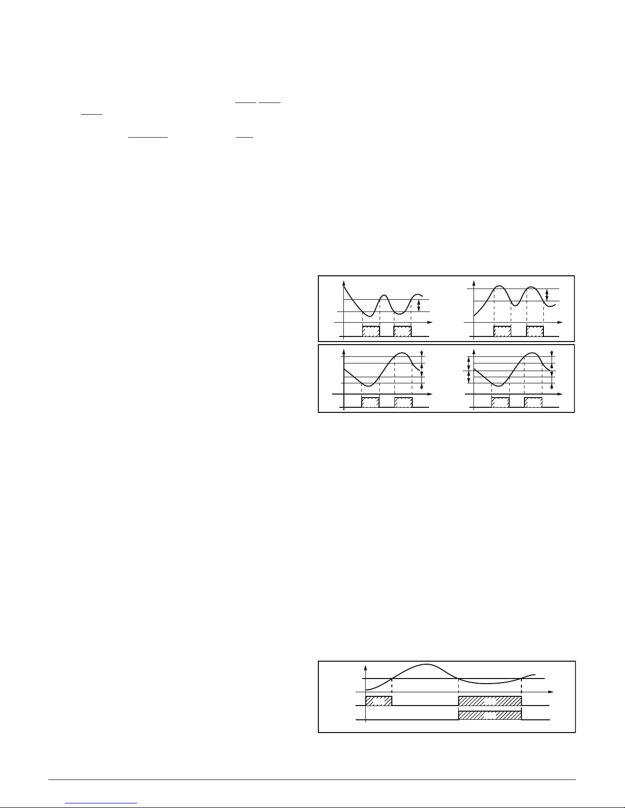
[19] AL1t - Alarm 1 type
Available: Always.
Range: • When at least one output is programmed as con-
trol output:
nonE Alarm not used;
LoAb Absolute low alarm;
HiAb Absolute high alarm;
LHAo Absolute band alarm with alarm indication
out of the band;
LHAi Absolute band alarm with alarm indication
inside the band;
SE.br Sensor break;
LodE Deviation low alarm (relative);
HidE Deviation high alarm (relative);
LHdo Relative band alarm with alarm indication
out of the band;
LHdi Relative band alarm with alarm indication
inside the band.
• When no output is programmed as control output:
nonE Alarm not used;
LoAb Absolute low alarm;
HiAb Absolute high alarm;
LHAo Absolute band alarm with alarm indication
out of the band;
LHAi Absolute band alarm with alarm indication
inside the band;
SE.br Sensor break.
Notes: 1. The relative and deviation alarms are “relative” to
the operative set point value.
LoAb
OUT
AL1
AL1
PV
HAL1
time
HiAb
off
off
off
OUT
AL1
AL1
PV
HAL1
time
off
off
off
ON ON ON ON
LHAo
PV
AL1H
HAL1
time
offoffoff
LHdo
OUT
AL1
AL1L
HAL1
PV
AL1H
SP
HAL1
time
OUT
AL1
-AL1L
HAL1
offoffoffON ON ON ON
2. The (SE.br) sensor break alarm will be ON when
the display shows ---- indication.
[20] Ab1 - Alarm 1 function
Available: When [19] AL1t is different from nonE.
Range: 0... 15 with the following rule:
+1 Not active at power up;
+2 Latched alarm (manual reset);
+4 Acknowledgeable alarm;
+8
Relative alarm not active at set point change.
Example: Setting Ab1 equal to 5 (1+4) the alarm 1 will be
“Not active at power up” and “Acknowledgeable”.
Notes: 1. The “Not active at power up” selection allows to
inhibit the alarm function at instrument power up
or when the instrument detects a transfer from:
• Manual mode (oPLo) to Auto mode;
• Stand-by mode to Auto mode.
The alarm will be automatically enabled when the
measured value reaches, for the first time, the
alarm threshold ±hysteresis (in other words, when
the initial alarm condition disappears).
PWR ON
AL1
PV
time
offoff
Ab1 = +1
Ab1 = +0
offoff
ON ON
ON
Page 10
Ascon Tecnologic - KX6 - ENGINEERING MANUAL - PAG. 10
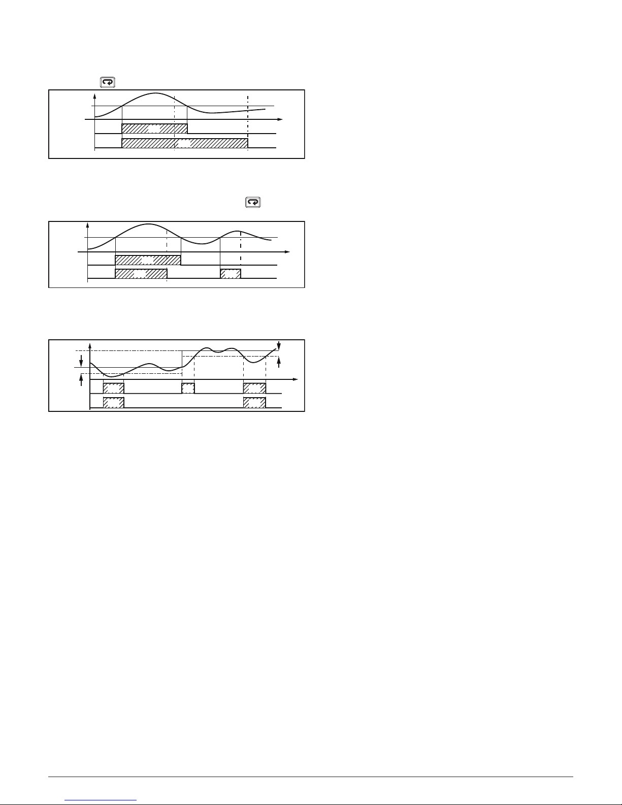
2. A “Latched alarm” (manual reset) is an alarm
that remains active even if the conditions that
generated the alarm no longer persist. Alarm
reset can be done only by an external
command
( button, digital input or serial link).
Alarm reset Alarm reset
AL1
PV
time
offoff
Ab1 = +2
Ab1 = +0
offoff
ON
ON
3. An “Acknowledgeable” alarm is an alarm that can
be reset even if the conditions that generated the
alarm are still present. Alarm acknowledge can be
done only by an external command ( button,
digital inputs or serial link).
Alarm ACK Alarm ACK
AL1
PV
time
offoff
Ab1 = +4
Ab1 = +0
offoff off
ON
ON ON
A “relative alarm not active at set point change” is
an alarm that masks the alarm condition after a
set point change until process variable reaches the
alarm threshold ± hysteresis.
Sp2
Sp1
PV
time
Ab1 = +8
Ab1 = +0
ON
offoff
AL1
offoffoff
AL1
ON ON ON
ON
4. The instrument does not store in EEPROM the
alarm status. For this reason, the alarm status
will be lost if a power down occurs.
[21] AL1L - For High and low alarms, it is the low
limit of the AL1 threshold
-
For band alarm, it is low alarm threshold
Available: When [19] AL1t is different from nonE or
[19] AL1t is different from SE.br.
Range: From -1999 to [22] AL1H engineering units.
[22] AL1H - For High and low alarms, it is the high
limit of the AL1 threshold
- For band alarm, it is the high alarm
threshold
Available: When [19] AL1t is different from nonE or
[19] AL1t is different from SE.br.
Range: From [21] AL1L to 9999 engineering units.
[23] AL1- Alarm 1 threshold
Available: When:
[19] AL1t = LoAb - Absolute low alarm;
[19] AL1t = HiAb - Absolute high alarm;
[19] AL1t = LodE - Deviation low alarm (relative);
[19] AL1t = LidE - Deviation high alarm (relative).
Range: From [21] AL1L to [22] AL1H engineering units.
[24] HAL1 - Alarm 1 hysteresis
Available: When [19] AL1t is different from nonE or
[19] AL1t is different from SE.br.
Range: 1... 9999 engineering units.
Notes: 1. The hysteresis value is the difference between
the Alarm threshold value and the point the Alarm
automatically resets.
2. When the alarm threshold plus or minus the
hysteresis is out of input range, the instrument will
not be able to reset the alarm.
Example: Input range 0... 1000 (mBar).
– Set point equal to 900 (mBar);
– Deviation low alarm equal to 50 (mBar);
– Hysteresis equal to 160 (mBar) the theoretical reset point is
900 - 50 + 160 = 1010 (mBar) but this value is out of range.
The reset can be made only by turning the instrument
OFF, removing the condition that generate the alarm and
then turn the instrument ON again.
– All band alarms use the same hysteresis value for both
thresholds;
– When the hysteresis of a band alarm is bigger than the
programmed band, the instrument will not be able to reset
the alarm.
Example: Input range 0... 500 (°C).
– Set point equal to 250 (°C);
– Relative band alarm;
– Low threshold equal to 10 (°C);
– High threshold equal to 10 (°C);
– Hysteresis equal to 25 (°C).
[25] AL1d - Alarm 1 delay
Available: When [19] AL1t is different from nonE.
Range: 0 oFF
1... 9999 seconds.
Note: The alarm goes ON only when the alarm condition
persists for a time longer than [25] AL1d time but the
reset is immediate.
[26] AL1o - Alarm 1 enabling during Stand-by mode
and out of range indications
Available: When [19] AL1t is different from nonE.
Range: 0 Never;
1 During stand by;
2 During overrange and underrange;
3
During overrange, underrange and stand-by.
]AL2 Group - Alarm 2 parameters
[27] AL2t - Alarm 2 type
Available: Aways.
Range: • When at least one output is programmed as con-
trol output:
nonE Alarm not used;
LoAb Absolute low alarm;
HiAb Absolute high alarm;
LHAo Absolute band alarm with alarm indication
out of the band;
LHAi Absolute band alarm with alarm indication
inside the band;
SE.br Sensor break;
LodE Deviation low alarm (relative);
HidE Deviation high alarm (relative);
LHdo Relative band alarm with alarm indication
out of the band;
LHdi Relative band alarm with alarm indication
inside the band.
Page 11

Ascon Tecnologic - KX6 - ENGINEERING MANUAL - PAG. 11
• When no output is programmed as control output:
nonE Alarm not used;
LoAb Absolute low alarm;
HiAb Absolute high alarm;
LHAo Absolute band alarm with alarm indication
out of the band;
LHAi Absolute band alarm with alarm indication
inside the band;
SE.br Sensor break.
Note: The relative alarm are “relative” to the current set point.
[28] Ab2 - Alarm 2 function
Available: When [27] AL2t is different from nonE.
Range: 0... 15 with the following rule:
+1 Not active at power up;
+2 Latched alarm (manual reset);
+4 Acknowledgeable alarm;
+8
Relative alarm not active at set point change.
Example: Setting Ad2 equal to 5 (1+4) the alarm 2 will be
“not active at power up” and “Acknowledgeable”.
Note: For other details see [20] Ab1 parameter.
[29] AL2L - For High and low alarms, it is the low
limit of the AL2 threshold
-
For band alarm, it is low alarm threshold
Available: When [24] AL2t is different from nonE or
[24] AL2t is different from SE.br.
Range: -1999 to [27] AL2H engineering units.
[30] AL2H
- For High and low alarms, it is the high
limit of the AL2 threshold
-
For band alarm, it is high alarm threshold
Available: When [27] AL2t is different from nonE or
[27] AL2t is different from SE.br.
Range: From [26] AL2L to 9999 engineering units.
[31] AL2 - Alarm 2 threshold
Available: When:
[27] AL2t = LoAb Absolute low alarm;
[27] AL2t = HiAb Absolute high alarm;
[27] AL2t = LodE Deviation low alarm (relative);
[27] AL2t = LidE Deviation high alarm (relative).
Range: From [29] AL2L to [30] AL2H engineering units.
[32] HAL2 - Alarm 2 hysteresis
Available: When [27] AL2t is different to nonE or [27] AL2t
is different from SE.br.
Range: 1... 9999 engineering units.
Note: For other details see [24] HAL1 parameter.
[33] AL2d - Alarm 2 delay
Available: When [27] AL2t different from nonE.
Range: From oFF (0) to 9999 seconds.
Note: The alarm goes ON only when the alarm condition
persist for a time longer than [33] AL2d time but the
reset is immediate.
[34] AL2o - Alarm 2 enabling during Stand-by mode
and out of range indications
Available: When [27] AL2t different from nonE.
Range: 0 Never;
1 During stand by;
2 During overrange and underrange;
3
During overrange, underrange and stand-by.
] LbA group - Loop break alarm
General note about LBA alarm
The LBA operate as follows: applying the 100% of the power
output to a process, the process variable, after a time due to the
process inertia, begins to change in a known direction (increases
for an heating action or decreases for a cooling action).
Example: If I apply 100% of the power output to a furnace,
the temperature must go up unless one of the component in
the loop is faulty (heater, sensor, power supply, fuse, etc...)
The same philosophy can be applied to the minimum power.
In our example, when I turn OFF the power to a furnace, the
temperature must go down, if not the SSR is in short circuit,
the valve is jammed, etc..
LBA function is automatically enabled when the PID requires
the maximum or the minimum power.
When the process response is slower than the programmed
limit the instrument generates an alarm.
Notes: 1. When the instrument is in manual mode, the LBA
function is disabled.
2. When LBA alarm is ON the instrument continues
to perform the standard control. If the process
response comes back into the programmed limit,
the instrument automatically resets the LBA alarm.
[35] LbAt - LBA time
Available: Always.
Range: • oFF = LBA not used;
• 1... 9999 seconds.
[36] LbSt - Delta measure used by LBA during
Soft start
Available: When [35] LbAt is different from oFF.
Range: • oFF = loop break alarm is inhibit during soft start;
• 1... 9999 engineering units.
[37] LbAS - Delta measure used by loop break
alarm (loop break alarm step)
Available: When [35] LbAt is different from oFF.
Range: 1... 9999 engineering units.
[38] LbcA - Condition for LBA enabling
Available: When [35] LbAt is different from oFF.
Range: uP Enabled when the PID requires the maxi-
mum power only;
dn Enabled when the PID requires the mini-
mum power only;
both
Enabled in both condition (when the PID re-
quires the maximum or the minimum power).
LBA application example:
LbAt (LBA time) = 120 seconds (2 minutes);
LbAS (delta LBA) = 5°C.
The machine has been designed in order to reach 200°C in
20 minutes (20°C/min).
When the PID demands 100% power, the instrument starts
the time count.
During time count if the measured value increases more
than 5°C, the instrument restarts the time count. Otherwise
if the measured value does not reach the programmed delta
(5°C in 2 minutes) the instrument will generate the alarm.
Page 12
Ascon Tecnologic - KX6 - ENGINEERING MANUAL - PAG. 12
]rEG group - Control parameters.
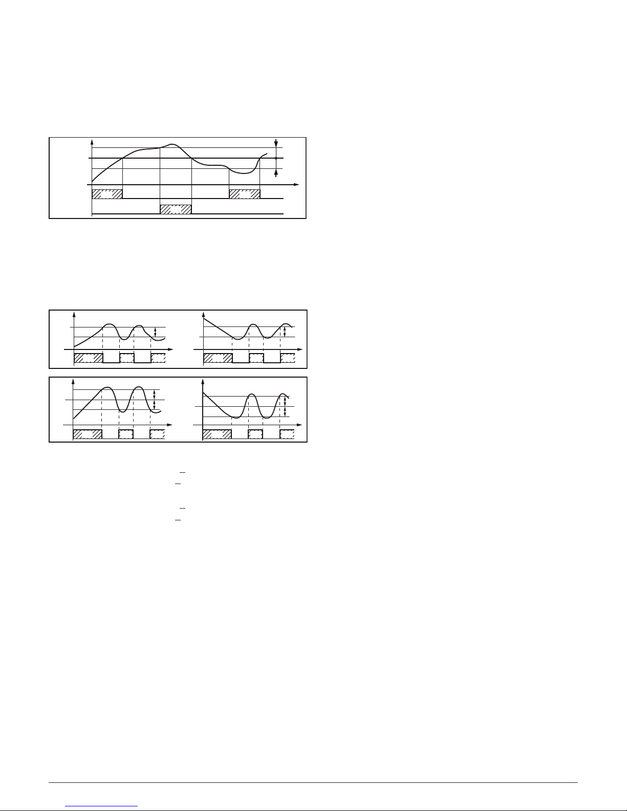
[39] cont - Control type:
Available: When at least one output is programmed as con-
trol output (H.rEG or C.rEG).
Range: • When two control actions (heat & cool) are pro-
grammed:
Pid PID (heat and cool);
nr
Heat/Cool ON/OFF control with neutral zone;
HSEt
HSEt
SP
PV
time
OUTH.rEG
(heating)
OUTc.rEG
(cooling)
offON ON
off off
ON
• When one control action (heat or cool) is programmed:
Pid PID (heat or cool);
On.FA ON/OFF asymmetric hysteresis;
On.FS ON/OFF symmetric hysteresis;
3Pt
Servomotor control (available when Out 1
and Out 2 have been ordered as “MM”).
HEAt - On.FA
OUT
H.rEG
SP
PV
HSEt
time
off off
CooL-On.FA
OUT
C.rEG
SP
PV
HSEt
time
ON ON ON
off off
ON ON ON
HEAt - On.FS
SP
PV
HSEt
HSEt
time
CooL-On.FS
SP
PV
HSEt
HSEt
time
OUT
H.rEG
off off
OUT
C.rEG
ON ON ON off offON ON ON
Notes: 1. ON/OFF control with asymmetric hysteresis:
• OFF when PV > SP;
• ON when PV < (SP - hysteresis).
2. ON/OFF control with symmetric hysteresis:
• OFF when PV > (SP + hysteresis);
• ON when PV < (SP - hysteresis).
[40] Auto - Auto tune selection
Ascon Tecnologic has developed three auto-tune algorithms:
– Oscillating auto-tune;
– Fast auto-tune;
– EvoTune.
1. The oscillating auto-tune is the usual auto-tune and:
• It is more accurate;
• Can start even if PV is close to the set point;
• Can be used even if the set point is close to the
ambient temperature.
2. The fast type is suitable when:
• The process is very slow and you want to be operative in a short time;
• When an overshoot is not acceptable;
• In multi-loop machinery where the fast method reduces
the calculation error due to the effect of the other loops.
3. The EvoTune type is suitable when:
• You have no information about your process;
• You can not be sure about the end user skills;
• You desire an auto tune calculation independently
from the starting conditions (e.g. set point change
during tune execution, etc).
Note: Fast auto-tune can start only when the measured
value (PV) is lower than (SP + 1/2 SP).
Available: When [39] cont = PID or 3Pt.
Range: -4... 8 where:
-4 Oscillating auto-tune with automatic restart at
all set point change;
-3 Oscillating auto-tune with manual start;
-2 Oscillating auto-tune with automatic start at the
first power up only;
-1 Oscillating auto-tune with automatic restart at
every power up;
0 Not used;
1 Fast auto tuning with automatic restart at every
power up;
2 Fast auto-tune with automatic start at the first
power up only;
3 FAST auto-tune with manual start;
4 FAST auto-tune with automatic restart at all set
point change.
5
EvoTune with automatic restart at every power up;
6 EvoTune with automatic start at the first power
up only;
7 EvoTune with manual start;
8 EvoTune with automatic restart at all set point
change.
[41] tunE - Manual start of the auto-tune
Available: When [39] cont = PID or 3Pt.
Range: oFF
The instrument is not performing the auto-tune;
on The instrument is performing the auto-tune.
[42] HSEt - Hysteresis of the ON/OFF control
Available: When [39] cont is different from PID or 3Pt.
Range: 0... 9999 engineering units.
[43] Pb - Proportional band
Available: When [39] cont = PID or 3Pt.
Range: 1... 9999 engineering units.
Note: Auto-tune functions calculate this value.
[44] ti - Integral time
Available: When [39] cont = PID or 3Pt.
Range: OFF = Integral action excluded;
1... 9999 seconds;
inF= Integral action excluded (reserved).
Note: Auto-tune functions calculate this value.
[45] td - Derivative time
Available: When [39] cont = PID or 3Pt.
Range: oFF - derivative action excluded;
1... 9999 seconds.
Note: Auto-tune functions calculate this value.
[46] Fuoc - Fuzzy overshoot control
This parameter reduces the overshoot usually present at
instrument start up or after a set point change and it will be
active only in this two cases.
Setting a value between 0.00 and 1.00 it is possible to slow
down the instrument action during set point approach.
Setting Fuoc = 1 this function is disabled.
Page 13

Ascon Tecnologic - KX6 - ENGINEERING MANUAL - PAG. 13
PV
SP
time
2
1
3
Available: When [39] cont = PID or 3Pt.
Range: 0... 2.00.
Note: Fast auto-tune calculates the Fuoc parameter while
the oscillating one sets it equal to 0.5.
[47] tcH - Cycle time of the heating output
Available: When at least one output is programmed in order
to be the heating output (H.rEG),
[56] cont = PID.
Range: 1.0... 130.0 seconds.
[48] rcG - Power ratio between heating and
cooling action (relative cooling gain)
The instrument uses the same PID parameter set for heat
and for cool action but the efficiency of the two actions are
usually different.
This parameter allows to define the ratio between the efficiency
of the heating system and the efficiency of the cooling one.
An example will help us to explain you the philosophy.
Consider one loop of a plastic extruder. The working
temperature is equal to 250°C.
When you want to increase the temperature from 250
to 270°C (DT = 20°C) using 100% of the heating power
(resistor), you will need 60 seconds.
On the contrary, when you want to decrease the temperature
from 250 to 230°C (DT = 20°C) using 100% of the cooling
power (fan), you will need 20 seconds only.
In our example the ratio is equal to 60/20 = 3 ([67] rcG = 3)
and it say that the efficiency of the cooling system is 3 time
more efficient of the heating one.
Available: When two control action are programmed
(H.rEG and c.rEG) and [39] cont = PID.
Range: 0.01... 99.99
Note: Auto-tune functions calculate this value.
[49] tcc - Cycle time of the cooling output
Available: When at least one output is programmed in order
to be the cooling output (c.rEG), [56] cont = PID.
Range: 1.0... 130.0 seconds.
[50] rS - Manual reset (integral pre-load)
It allows to drastically reduce the undershoot due to a
hot restart. When your process is steady, the instrument
operates with a steady power output (e.g.: 30%).
If a short power down occurs, the process restarts with a
process variable close to the set point while the instrument
starts with an integral action equal to zero.
Setting a manual reset equal to the average power output (in our
example 30%) the instrument will start with a power output equal
to the value it will use at steady state (instead of zero) and the
undershoot will become very little (in theory equal to zero).
Available: When [39] cont = PID or 3Pt.
Range: -100.0... +100.0%.
[51] Str.t - Servomotor stroke time
Available: When [39] cont = 3Pt.
Range: 5... 300 seconds;
Note: When a open loop with potentiometer input is selected,
this parameter ia automatically calculated by the “automatic calibration system” (see [48] P.cAL parameter).
[52] db.S - Servomotor dead band
Available: When [39] cont = 3Pt.
Range: 0... 100%.
[53] OP.L - Minimum power output
Available: When: [39] cont = PID;
[39] cont = 3Pt and [58] Pot = Pot.o;
[39] cont = 3Pt and [58] Pot = Pot.c.
Range: -100... [54]OP.H%.
[54] OP.H - Maximum power output
Available: When: [39] cont = PID;
[39] cont = 3Pt and [58] Pot = Pot.o;
[39] cont = 3Pt and [58] Pot = Pot.c.
Range: [53] OP.L ... 100%.
[55] St.P - Maximum power output used during
soft start
Available: When: [39] cont = PID;
[39] cont = 3Pt and [58] Pot = Pot.c.
Range: -100... +100%.
Notes: 1. When St.P parameter have a positive value, the
limit will be applied to the heating output(s) only.
2. When St.P parameter have a negative value, the
limit will be applied to the cooling output(s) only.
3. When a program with automatic start at power
up and soft start function are programmed, the
instrument performs the soft start and than the
program function.
4. The auto-tune function will be performed after soft
start function.
5. The Soft start function is available also when ON/
OFF control is used.
[56] SSt - Soft start time
Available: When: [39] cont = PID;
[39] cont = 3Pt and [58] Pot = Pot.c.
Range: oFF Function not used;
0.01... 7.59 hh.mm;
inF Soft start always active.
[57] SS.tH - Threshold for soft start disabling
Available: When: [39] cont = PID;
[39] cont = 3Pt and [58] Pot = Pot.c.
Range: -1999... 9999 engineering units.
Notes: 1. When the power limiter has a positive value (the
limit is applied to the heating action) the soft start
function will be aborted when the measured value
is greater or equal to SS.tH parameter.
2. When the power limiter has a negative value (the
limit is applied to the cooling action) the soft start
function will be aborted when the measured value
is lower or equal to SS.tH parameter.
[58] Pot - Potentiometer enabling
Available: When [39] cont = 3Pt.
Range: nonE Potentiometer not used;
Pot.o Potentiometer used for indication only;
Pot.c Potentiometer used for feedback.
Page 14
Ascon Tecnologic - KX6 - ENGINEERING MANUAL - PAG. 14
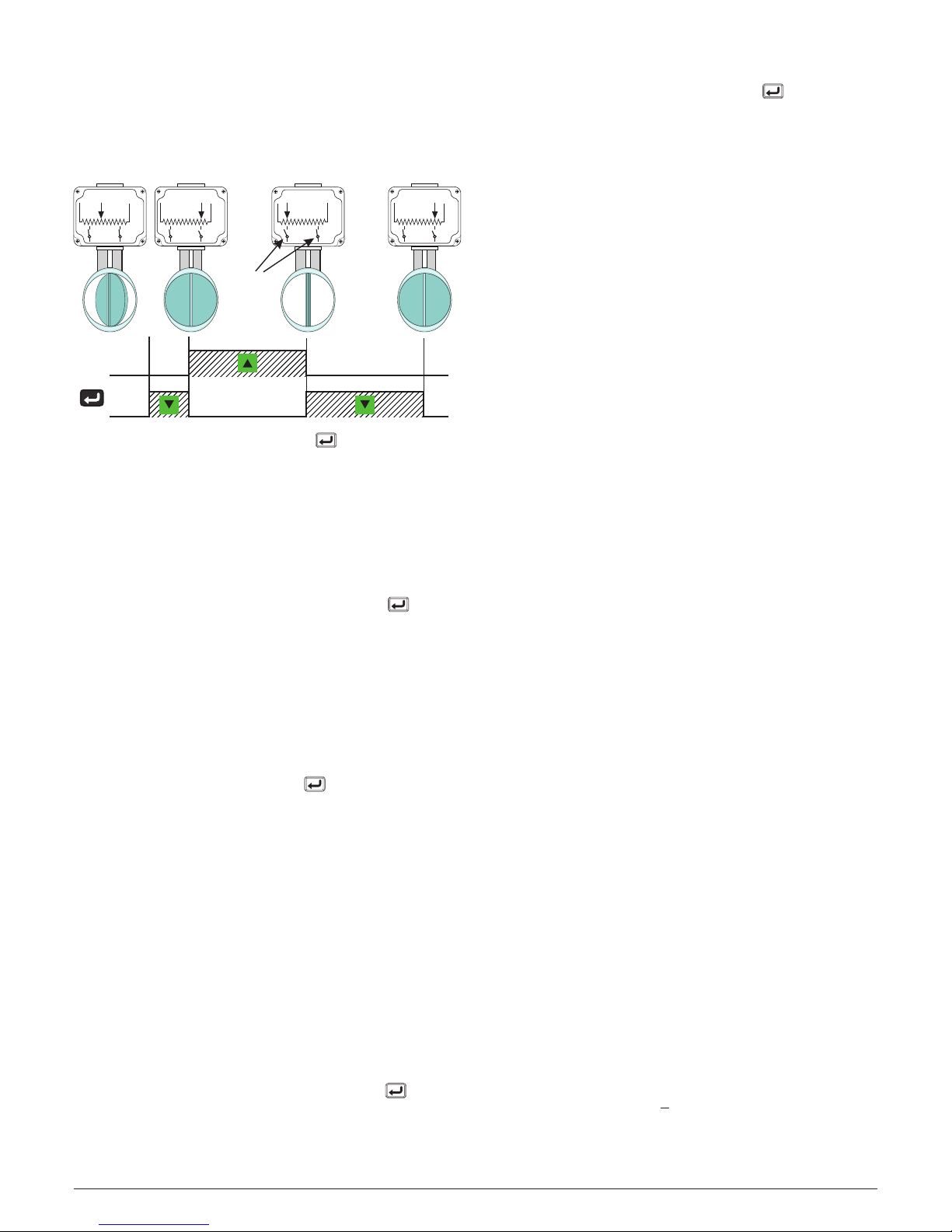
[59] P.cAL - Automatic Potentiometer Calibration
Available: When [39] cont = 3Pt and [58] Pot = Pot.c.
Range: no
The automatic
potentiometer
calibration
does not start;
YES The automatic potentiometer calibration
starts.
Notes about Automatic Potentiometer Calibration
Out 2
Out 1
Potentiometer
calibration
Valve travel
time calculation
Loop
ready
Servomotor
Limit
Switches
When [59] P.cAL = YES, pushing the button the
instrument operates as follows:
1. The instrument goes in MANUAL mode;
2. The instrument energizes the Open valve output (Out 1),
then verifies if the measure of the potentiometer position
starts growing.
2.1 If the potentiometer position value decreases, the
instrument de-energizes
Out 1 and shows the message: E.P.rE (Error - potentiometer reversed).
The message disappears as soon as the button is
pressed (the instrument returns to the P.cAL parameter).
2.2 If, after 10 seconds, the measure does not increase,
the instrument de-energizes the Open valve relay
and energizes the Close valve relay (Out 2).
2.2.1. If, after 10 seconds, the measure does not
de
crease, the instrument de-energizes Out 2 re-
lay
, considers the potentiometer disconnected
and shows the message no.Pt (No potentiometer) on the middle display. The message disappears as soon as the button is pressed (the
instrument returns at P.cAL parameter).
2.2.2. If the measure starts decreasing, the instrument keeps active the “Close valve” output
until the measure changes. When the measure stops changing for more than 5 seconds,
the instrument stores this value as 0% (zero)
position and goes to the next step.
3. The instrument de-energizes the Close valve relay
and energizes the Open valve relay until the measured
value increases.
4. When the measure stops changing for more than 5 seconds,
the instrument stores this value as 100% position.
4.1 If the count detected from 0% to 100% is lower than
30% of the instrument counts, on the middle display
the instrument shows the error message:
E.P.cA (Potentiometer calibration error).
The message disappears as soon as the button
is
pressed (the instrument returns at P.cAL parameter).
5. During the potentiometer calibration the instrument
detects the (real) valve stroke time and stores it in the
Str.t (Stroke time) parameter.
At the end of the automatic potentiometer calibration the
instrument moves the valve to zero and shows “donE”.
The message disappears as soon as the button
is
pressed (the instrument returns at P.cAL parameter).
Note also:
If, during normal operations, the instrument detects a potentiometer malfunction, it operates as follows:
– Switches immediately to the “Servo motor without
potentiometer” control mode;
– Ignores parameters [53] OP.L and [54] OP.H;
– The potentiometer icon starts flashing to warn the user
about the problem detected.
[60] PoSi - Valve position at start up
Available: When [39] cont = 3Pt and [58] Pot = nonE.
Range: no No action;
oPEn At all power ON the instrument energizes
the Open valve relay for the programmed
stroke time;
CloSe At all power up the instrument energizes
the Close valve relay for the programmed
stroke time.
]SP Group - Set point parameters
[61] nSP - Number of used set points
Available: Always.
Range: 1... 4.
Note: When you change the value of this parameter, the
instrument operates as follows:
• [68] A.SP parameter will be forced to SP.
• The instrument verifies that all used set point are with-
in the limits programmed by [62] SPLL and [63] SPHL.
If an SP is out of this range, the instrument forces it to
the maximum acceptable value.
[62] SPLL - Minimum set point value
Available: Always.
Range: From -1999 to [63] SPHL engineering units
Notes: 1. When you change the [62] SPLL value, the instru-
m
ent checks all local set points (SP, SP2, SP3 and
SP4 parameters).
If an SP is out of this range, the
instrument forces it to the maximum acceptable value
2. A [62] SPLL change produces the following actions:
• When [69] SP.rt = SP the remote set point will
be forced to be equal to the active set point.
• When [69] SP.rt = trim the remote set point
will be forced to zero.
• When [69] SP.rt = PErc the remote set point
will be forced to zero.
[63] SPHL - Maximum set point value
Available: Always.
Range: From [62] SPLL to 9999 engineering units.
Note: For other details see [62] SPLL parameter.
[64] SP - Set Point 1
Available: Always.
Range: From [62] SPLL to [63] SPHL engineering units.
[65] SP 2 - Set Point 2
Available: When [61] nSP > 2.
Range: From [62] SPLL to [63] SPHL engineering units.
Page 15

Ascon Tecnologic - KX6 - ENGINEERING MANUAL - PAG. 15
[66] SP 3 - Set Point 3
Available: When [61] nSP > 3.
Range: From [62] SPLL to [63] SPHL engineering units.
[67] SP 4 - Set Point 4
Available: When [61] nSP =4.
Range: From [62] SPLL to [63] SPHL engineering units.
[68] A.SP - Selection of the active Set point
Available: When [61] nSP > 2
Range: From SP to [61] nSP.
Notes: 1. A [68] A.SP change produces the following actions:
• When [69] SP.rt = SP - the remote set point
is forced to be equal to the active set point;
• When [69] SP.rt = trin - the remote set point
is forced to zero;
• When [69] SP.rt = PErc - the remote set
point is forced to zero.
2. SP2, SP3 and SP4 selection are shown only
when the relative set point is enabled (see
[61] nSP parameter).
[69] SP.rt - Remote set point type
These instruments will communicate with each other, using
RS 485 serial interface without a PC. An instrument can be
set as a Master while the other are (as usual) Slave units. The
Master unit can send his operative set point to the slave units.
In this way, for example, it is possible to change simultaneously
the set point of 20 instruments by changing the set point of the
master unit (e.g. hot runner application).
[69] SP.rt parameter defines how the slaves units will use the
value coming from serial link.
The [86] tr.SP [selection of the value to be retransmitted (Master)]
parameter allows to define the value sent by master unit.
Available: When serial interface is present.
Range: rSP The value coming from serial link is used
as remote set point (RSP).
trin The value coming from serial link will be
algebraically added to the local set point
selected by A.SP and the sum becomes
the operative set point.
PErc The value coming from serial will be scaled
on the input range and this value will be
used as remote set point.
Note: A [69] SPrt change produces the following actions:
• When [69] SP.rt = rSP - the remote set point will be
forced to be equal to the active set point;
• When [69] SP.rt = trin - the remote set point will be
forced to zero;
• When [69] SP.rt = PErc - the remote set point will be
forced to zero.
Example: A 6 zone reflow-oven for PCB. The master unit
sends its set point value to 5 other zones (slave controllers).
The Slave zones use it as a set point trim.
The first zone is the master zone and it uses a set point
equal to 210°C.
The second zone has a local set point equal to -45°C.
The third zone has a local set point equal to -45 (°C).
The fourth zone has a local set point equal to -30.
The fifth zone has a local set point equal to +40.
The sixth zone has a local set point equal to +50.
In this way, the thermal profile will be the following:
– Master SP = 210°C;
– Second zone SP = 210 -45 = 165°C;
– Third zone SP = 210 -45 = 165°C;
– Fourth zone SP = 210 - 30 = 180°C;
– Fifth zone SP = 210 + 40 = 250°C;
– Sixth zone SP = 210 + 50 = 260°C.
Changing the SP of the master unit, all the other slave units
will immediately change their operative set point.
[70] SPLr - Local/remote set point selection
Available: When at least one output is programmed as
control output.
Range: Loc Local set point selected by [68] A.SP;
rEn Remote set point (coming from serial link).
[71] SP.u - Rate of rise for positive set point
change (ramp up)
Available: When at least one output is programmed as
control output.
Range: 0.01... 99.99 units per minute;
inF Ramp disabled (step transfer).
[72] SP.d - Rate of rise for negative set point
change (ramp down)
Available: When at least one output is programmed as
control output.
Range: 0.01... 99.99 units per minute;
inF Ramp disabled (step transfer).
General note about remote set point:
When the remote set point (RSP) with trim action is
programmed, the local set point range becomes:
from [62] SPLL + RSP to [63] SPHL - RSP.
]PAn group - Operator HMI
[73] PAS2
- Level 2 password: Limited access level
Available: Always.
Range: oFF Level 2 not protected by password
(as level 1 = Operator level);
1... 200.
[74] PAS3
- Level 3 password:
Complete configuration level
Available: Always.
Range: 3... 200.
Note: Setting [73] PAS2 equal to [74] PAS3, the level 2 will
be masked.
[75] uSrb - button function during RUN TIME
Available: Always.
Range: nonE No function;
tunE Auto-tune/self-tune enabling. A single
press (longer than 1 s) starts the auto-tune;
oPLo
Manual mode. The first pressure puts the
instrument in manual mode (oPLo) while the
second one puts the instrument in Auto mode;
AAc Alarm acknowledge;
ASi Alarm reset;
St.by Stand by mode. The first press puts the in-
strument in stand by mode while a second
one puts the instrument in Auto mode;
SP1.2 SP/SP2 selection.
Notes: 1. When “SP1.2” is used, every press of the key
(longer than 1 second) revert the set point selected.
When a new set point is selected using the key,
the display will show for 2 seconds the acronym of
Page 16

Ascon Tecnologic - KX6 - ENGINEERING MANUAL - PAG. 16
the new set point (e.g. SP2).
2. When “SP1.2” is used, the [61] nSP parameter
must be equal to 2.
[76] diSP - Middle Display Management
Available: Always.
Range: nonE Display not used;
SPF Final set point;
SPo Operative set point;
AL1 Alarm 1 threshold;
AL2 Alarm 2 threshold;
Po Power output
[77] di.CL - Display colour
Available: Always.
Range: 0 The display colour is used to show the actual
deviation (PV - SP);
1 Display red (fix);
2 Display green (fix);
3 Display orange (fix).
[78] AdE - Deviation for display colour management
Available: When [77] di.CL = 0.
Range: 1... 9999 engineering units.
[79] diS.t - Display time out
Available: Always.
Range: oFF The display is ever ON;
0.1... 99.59 minutes and seconds.
Note: This function allows to turn OFF the display when no
alarm is present and no action is made on the instrument.
When diS.t is different from oFF and no button is
pressed for more than the programmed time out, the
display goes OFF and only 4 segments of the less
significant digit are turned ON in sequence in order to
show that the instrument is working correctly.
If an alarm occurs or a button is pressed, the display
will come back to the normal operation.
[80] FiLd - Filter on the displayed value
Available: Always.
Range: oFF Filter disabled;
0.1... 20.0 engineering units.
Note: This is a “window filter” related to the set point, it is ap-
plied to the displayed value only and has no effect on the
other functions of the instrument (control, alarms, etc.).
[81] dSPu - Status of the instrument at power up
Available: Always.
Range: AS.Pr Starts in the same way it was prior to the
power down;
Auto Starts in Auto mode;
oP.0 Starts in manual mode with a power output
equal to zero.
St.bY Starts in stand-by mode
Note: When you change the value of [82] oPr.E, the
instrument forces [83] oPEr parameter equal to Auto.
[82] oPr.E - Operative modes enabling
Available: Always.
Range: ALL All modes will be selectable by the next
parameter.
Au.oP Auto and manual (oPLo) mode only will be
selectable by the next parameter;
Au.Sb Auto and Stand-by modes only will be se-
lectable by the next parameter.
Note: Manual changing the value of [82] oPr.E, the
instrument forces parameter [83] oPEr = Auto.
[83] oPEr - Operative mode selection
Available: Always.
Range: When [82] oPr.E = ALL:
Auto = Auto mode;
oPLo = Manual mode;
St.bY = Stand by mode.
When [82] oPr.E = Au.oP:
Auto = Auto mode;
oPLo = Manual mode.
When [82] oPr.E = Au.Sb:
Auto = Auto mode;
St.bY = Stand by mode.
]Ser group - Serial link parameter
[84] Add - Instrument address
Available: Always.
Range: oFF = Serial interface not used;
1... 254.
[85] bAud - Baud rate
Available: When [73] Add different from oFF.
Range: 1200 1200 baud;
2400 2400 baud;
9600 9600 baud;
19.2 19200 baud;
38.4 38400 baud.
[86] trSP - Selection of the value to be
retransmitted (Master)
Available: When [72] Add different from oFF.
Range: nonE Retransmission not used (the instrument is
a slave);
rSP The instrument become a Master and it
retransmits the operative set point;
PErc The instrument become a Master and it
retransmits the power output.
Note: For more details see [69] SP.rt (Remote set point type)
parameter.
Page 17
Ascon Tecnologic - KX6 - ENGINEERING MANUAL - PAG. 17
]CAL group - User calibration group
This function allows to calibrate the complete measuring
chain and to compensate the errors due to:
– Sensor location;
– Sensor class (sensor errors);
– Instrument accuracy.
[87] AL.P - Adjust Low Point
Available: Always.
Range: -1999... (AH.P - 10) engineering units.
Note: The minimum difference between AL.P and AH.P is
equal to 10 Engineering Units.
[88] AL.o - Adjust Low Offset
Available: Always.
Range: -300... +300 engineering units.
[89] AH.P - Adjust High Point
Available: Always.
Range: From (AL.P + 10) to 9999 engineering units.
Note: The minimum difference between AL.P and AH.P is
equal to 10 Engineering Units.
[90] AH.o - Adjust High Offset
Available: Always.
Range: -300... +300 Engineering Units.
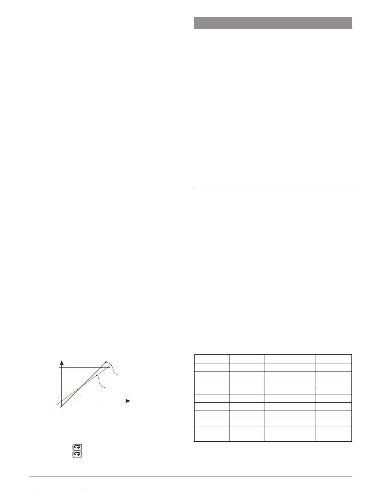
Example: Environmental chamber with an operative range:
10... 100°C.
1. Insert in the chamber a reference sensor connected with
a reference instrument (usually a calibrator).
2. Start the control of the instrument, and set a set point equal to
the minimum value of the operative range (e.g.: 10°C). When
the temperature in the chamber is steady, take note of the
temperature measured by the reference system (e.g.: 9°C).
3. Set [87] AL.P = 10 (low working point) and [88] AL.o = -1
(it is the difference between the reading of the instrument
and the reading of the reference system). Note that after
this set the measured value of the instrument is equal to
the measured value of the reference system.
4. Set a set point equal to the maximum value of the
operative range (e.g. 100°C). When the temperature
in the chamber is steady, take note of the temperature
measured by the reference system (e.g. 98°C).
5. Set [89] AH.P = 100 (low working point) and [90] AHo = +2
(it is the difference between the reading of the instrument
and the reading of the reference system). Note that after
this set the measured value of the instrument is equal to
the measured value of the reference system.
AH.P 100°C
AH.o = 2
AL.o = -1
AH.P 10°C
Real
curve
Modified
curve
The most important step of the configuration procedure is
completed.
In order to exit from configuration parameter procedure,
proceed as follows:
• Push button.
• Push button for more than 10 s. The instru-
ment will come back to the “standard display”.
7 PARAMETER PROMOTION
Another important step of the instrument configuration is due
to the possibility to create a custom HMI (interface) in order
to make the instrument easy to use for the operator and
comfortable for the assistance.
By a special procedure, named promotion, the OEM can
create two parameter subsets.
The first one is the “limited access” level. This subset is protected
by the password programmed by [73] PAS2 parameter.
The last subset is the “Operator” set (Level1). This level is
NOT password protected.
Notes: 1. The “limited access” parameter are collected in a list.
2. The sequence of the “limited access” parameters
is programmable and can be made according to
your needs.
3. The parameter sequence of the operator level is
the same programmed for “limited access” level
but only specified parameters can be displayed
and modified. This set must be create according
to your requirements.
7.1 Parameter promotion procedure
The limited access parameter set is a list, so that, before to
start promotion procedure, we suggest to operate as follows:
1. Prepare the exact parameter list you want to make
accessible for limited access.
2. Number the desired parameters in the same sequence
you want to have in the limited access.
3. Define which of the selected parameter will be available
in Operator level also.
Example: I would like to obtain the following limited access list:
• OPEr - Operative mode selection
• SP - first set point
• SP2 - Second set point
• A.SP - Set point selection
• AL1 - Alarm 1 threshold
• AL2 - Alarm 2 threshold
• Pb - Proportional band
• ti - Integral time
• td - Derivative time
• Aut.r - Manual start of the auto-tune
But I want that the operator to be able to change: the
operative mode, the SP value and the AL1 value. In this
case the promotion will be the following:
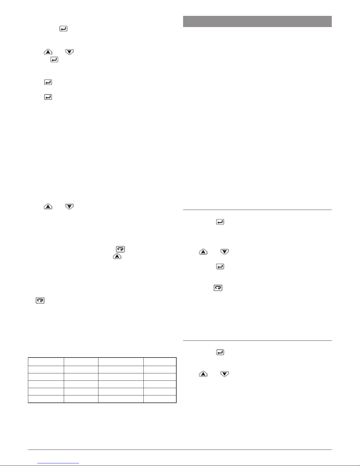
Parameter Promotion Limited Access Operator
- OPEr - o 1 OPEr OPEr
- SP - o 2 SP SP
- SP2 - A 3 SP2
- A.SP - A 4 A.SP
- AL1 - o 5 AL1 AL1
- AL2 - A 6 AL2
- Pb - A 7 Pb
- ti - A 8 ti
- td - A 9 td
- Aut.r - A 10 Aut.r
Page 18
Ascon Tecnologic - KX6 - ENGINEERING MANUAL - PAG. 18
Now, proceed as follows:
1. Push the button for more than 3 seconds.
2. The upper display will show PASS while the middle
display will show 0.
3. By and buttons set a password equal to -81.
4. Push button.
The instrument will show the acronym of the first
configuration parameter group
]
inP
.
5. By button select the group of the first parameter of
your list.
6. By button select the first parameter of your list
7. The upper display will show the acronym of the parameter
while the middle display will show his current promotion
level. The promotion level is defined by a letter followed
by a number. The letter can be:
c: It shows that this parameter is NOT promoted
and it is present only in configuration.
In this case the number is forced to zero.
A: It shows that this parameter has been promoted
to the limited access level.
The number will show the position in the limited
access list.
o: It shows that the parameter has been promoted
to the Operator level.
The number will show the position in the limited
access list.
8. By and buttons assign to this parameter the
desired position.
Note: Setting a value different from 0 the letter c will change
automatically to A and the parameter is automatically
promoted to the limited access level.
9. In order to modify the level from limited access
to operator and vice versa, push button and,
maintaining the pressure, push button.
The letter will change from A to o and vice versa.
10. Select the second parameter that you want to add to the
assistance level and repeat step 6, 7 and 8.
11. Repeat steps 5, 6, 7, 8 until the list has been completed.
12. When you need to exit from promotion procedure, push
button and maintain the pressure for more than 10 s.
The instrument will show the “standard display”.
Note: When you set the some number to two parameter, the
instrument will use only the last programmed parameter.
Example: In the previous example, I have set for SP2 a
promotion value equal to A3.
If now I set for SP3 a promotion value equal to o3, the
Limited Access list and the operator list becomes.
Parameter Promotion Limited Access Operator
- OPEr - o 1 OPEr OPEr
- SP - o 2 SP SP
- SP3 - o 3 SP3 SP3
- A.SP - A 4 A.SP
- AL1 - o 5 AL1 AL1
8 OPERATIVE MODES
As we said at paragraph 6.1, when the instrument is
powered, it starts immediately to work according to the
memorized parameter value.
In other words, the instrument has one status only, the “run
time” status.
During “run time” we can force the instrument to operate
in three different modes: Automatic mode, Manual mode or
Stand by mode:
– In Automatic mode the instrument drives automatically
the control output according to the parameter value set
and the set point/measured value.
– In Manual mode the upper display shows the measured
value while the
middle display shows the power output
[preceded by H (for heating) or C (for cooling)], MAN is lit
and the instrument allows you to set manually the control
output power.
No Automatic action will be made.
– In Stand by mode the instrument operates as an indicator.
It will show on the upper display the measured value and
on the middle display the set point alternately to the “St.bY”
messages and forces the control outputs to zero.
As we have seen, it is always possible to modify the value
assigned to a parameter independently from the operative
modes selected.
8.1 Modify a parameter during
“Operator level”
The instrument is showing the “standard display”.
1. Press the button.
2. The upper display will show the acronym of the first
parameter promoted to this level while the middle display
will show its value.
3. By and button assign to this parameter the
desired value.
4. Press the button in order to memorize the new value
and go to the next parameter.
5. When you want to come back to the “standard display”
push the button for more than 5 seconds.
Note: The parameter modification of the Operator level
is subject to a time out. If no button is pressed for
more than 10 seconds, the instrument goes back to
the “standard display” and the new value of the last
selected parameter will be lost.
8.2 Enter the “Limited access level”
The instrument is showing the “standard display”.
1. Press the button for more than 5 seconds;
2. The upper display will show PASS while the middle
display will show 0;
3. By and buttons set the value assigned to
[73] PAS2 (Level 2 password).
Notes: 1. The factory default password for configuration
parameters is equal to 20.
2. Operator and assistange level of Parameter
modification are protected by a time out. If
no button is pressed for more than 10 second
the instrument comes automatically back to
the Standard display, the new value of the last
selected parameter is lost and the parameter
modification procedure is closed.
Page 19

Ascon Tecnologic - KX6 - ENGINEERING MANUAL - PAG. 19
When you desire to remove the time out (e.g.
for the first configuration of an instrument) you
can use a password equal to 1000 plus the
programmed password
(e.g. 1000 + 20 [default] = 1020).
It is always possible to manually End the
parameter configuration procedure (see below).
3. During parameter modification the instrument
continues to perform the control.
In certain conditions (e.g. when a parameter
change can produces a heavy bump to the
process) it is advisable to temporarily stop the
controller from controlling during the programming
procedure (its control output will be Off). A
password equal to 2000 + the programmed value
(e.g. 2000 + 20 = 2020) will switch the control out
off during configuration. The control will restart
automatically when the para-meter modification
procedure will be manually ended.
4. Push button.
5. The instrument will show on the upper display the
acronym of the first parameter promoted to this
level and on the middle display its value.
6. By and buttons assign to this parameter
the desired value.
7. Press the button in order to memorize the
new value and go to the next parameter.
8. When you want to come back to the “standard
display” push the button for more than 5 s.
8.3 How to see but not modify the
“Limited access parameters”
Sometime it is necessary to give to the operator the possibility
to see the value assigned to the parameter promoted in the
Limited Access level but it is important that all changes are
made by authorized personnel only.
In this cases, proceed as follows:
1. Press the button for more than 5 seconds;
2. The upper display will show PASS while the middle
display will show 0;
3. By and button set the value -181;
4. Push button;
5. The upper display will show the acronym of the first
parameter promoted to the level 2 and middle display will
show its value;
6. Using button it is possible to see the value assigned
to all parameter present in level 2 but it will not be
possible to modify it;
7. It is possible to come back to the “standard display” by
pushing the button for more than 3 seconds or by
pushing no buttons for more than 10 seconds.
8.4 Automatic Mode
8.4.1 Keyboard function when the instrument
is in Auto mode
Performs the action programmed by [75] uSrb
( button function during RUN TIME) parameter.
Enters the parameter modification procedures.
Starts the “Direct set point modification” function (see
below).
Displays the “additional information” (see below).
8.4.2 Direct set point modification
This function allows to modify rapidly the set point value
selected by [68] A.SP (selection of the active Set point)
currently in progress.
The instrument is showing the “standard display”.
1. Push button.
The upper display shows the acronym of the selected set
point (e.g. SP2) and the middle display will show its value.
2. By and buttons, assign to this parameter the
desired value
3. Do not push any button for more than 5 second or
push the button.
In both cases the instrument stores the new value and
returns to the “standard display”.
Note: If the selected set point has not been promoted to the
Operator level, the instrument allows you to see the
value but not to modify it.
8.4.3 Additional information
This instrument is able to show you the power output
calculated by the PID.
1. When the instrument is showing the “standard display”
push button.
The middle display will show H or c followed by a number.
This value is the current power output calculated by the
PID. The H show you that the action is a Heating action
while the c show you that the action is a Cooling action.
2. Push button again. The instrument returns to the
“standard display”.
Note: The additional information visualization is subject to
a time out. If no button is pressed for more than 10
second the instrument comes automatically back to
the Standard display.
8.4.4 Display management
This instrument allows you to program (see parameter [67]
diS.t the time out of the display.
This function allows to turn OFF the display when no alarm
is present and no action is made on the instrument.
When [79] diS.t is different to OFF (display ever ON) and
no button is pressed for more than the programmed time
out, the display goes OFF and only 4 segments of the less
significant digit are turned ON in sequence in order to show
that the instrument is working correctly.
If an alarm occurs or a button is pressed, the display returns
to the normal operation.
Page 20
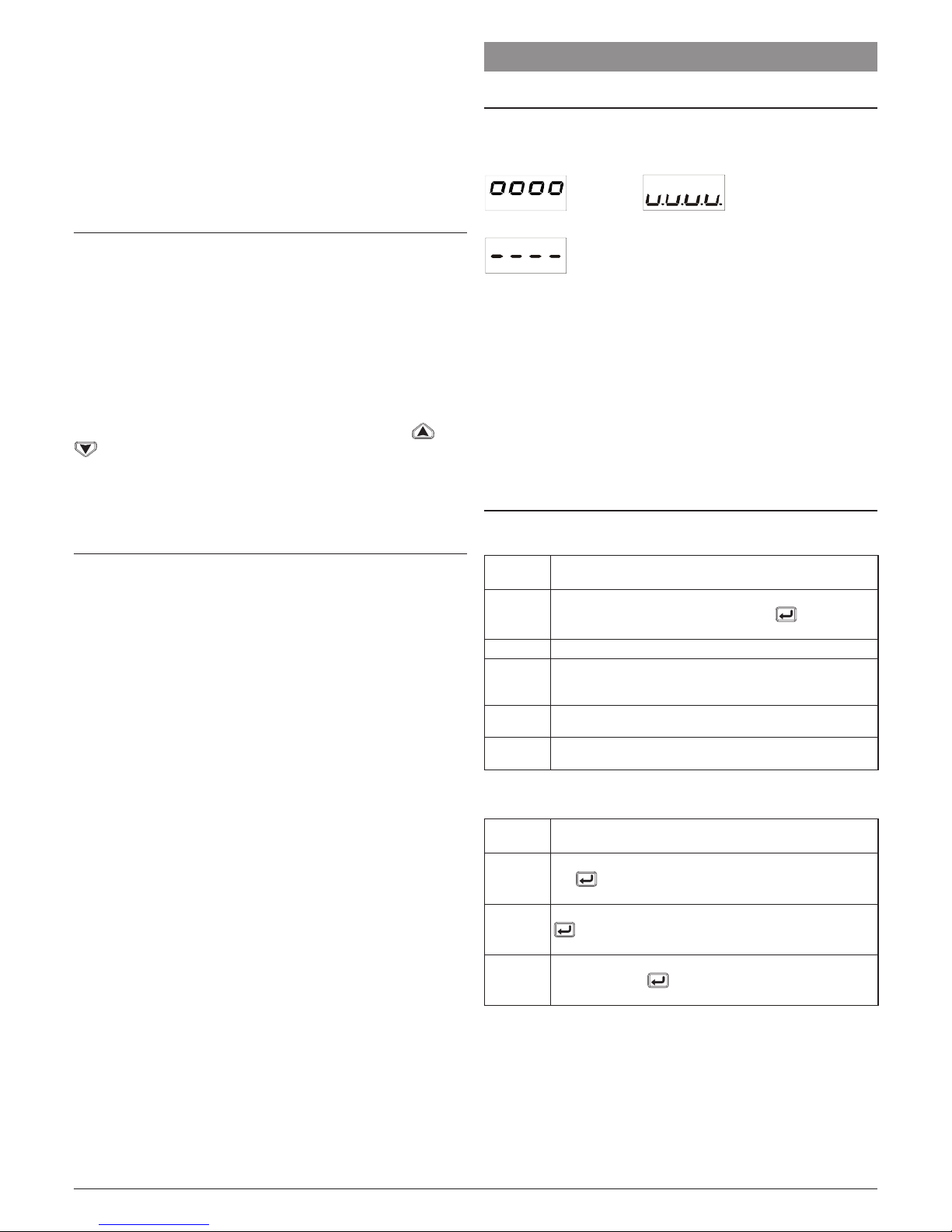
Ascon Tecnologic - KX6 - ENGINEERING MANUAL - PAG. 20
8.4.5 The display colour shows the Deviation
This instrument allows to program the deviation (PV - SP) for
colour display change (see parameter [78] AdE).
In this way the upper display will be:
– Amber when PV is lower than SP - AdE;
– Green when (SP - AdE) < PV<SP + AdE);
– Red when PV is higher than SP + AdE.
8.5 Manual mode
This operative mode allows you to deactivate automatic
control and manually set valve position.
When the instrument is in manual mode, the upper display shows
the measured value, the middle display shows the power output
[preceded by H (for heating action) or C (for cooling action)] while
the lower display continue to show the valve position (measured
or calculated according to [58] Pot parameter setting).
MAN LED is lit.
When manual control is selected, the instrument will start to
operate with the same power output as the last one supplied
by automatic mode and it can be modified using the and
buttons.
Notes: 1. During manual mode, the alarms are operative.
2. If you set manual modes during self-tune
execution, the self- tune function will be aborted.
8.6 Stand by mode
This operative mode also deactivates the automatic control
but forces the control output (valve position) to zero.
In this mode the instrument operates as an indicator.
When the instrument is in stand by mode the upper display
will show the measured value while the middle display will
show alternately the set point and the message “St.bY”.
Notes: 1. During stand by mode, the relative alarms are
disabled while the absolute alarms are operative
or not according to the ALxo (Alarm x enabling
during Stand-by mode) parameter setting.
2. If you set stand by mode during self-tune
execution, the self- tune function will be aborted.
3. When the instrument is swapped from stand
by to auto modes, the instrument will start
automatically the alarm masking, the soft start
functions and the auto-tune (if programmed).
9 ERROR MESSAGES
9.1 Out of range signals
The upper display shows the OVER-RANGE and UNDERRANGE conditions with the following indications:
Over-range Under-range
The sensor break will be signalled as an out of range
Note: When an over-range or an under-range is detected,
the alarms operate as in presence of the maximum or
the minimum measurable value respectively.
To check the out of span Error condition, proceed as follows:
1. Check the input signal source and the connecting line.
2. Make sure that the input signal is in accordance with the
instrument configuration. Otherwise, modify the input
configuration (see section 6.6).
3. If no error is detected, send the instrument to your
supplier to be checked.
9.2 List of possible errors
9.2.1 Controller errors
Displayed
message
Description
ErAT
Fast Auto-tune cannot start. The PV (measured value)
is too close to the set point. Push the button in
order to delete the error message
NoAt
Auto-tune not finished within 12 hours
ErEP
Possible problem in the instrument memory. The
message should automatically disappear, if the error
persists, send the instrument to your supplier
RonE
Possible problem of the firmware memory. If this error
is detected, send the instrument to your supplier
Errt
Possible problem of the calibration memory. If this error
is detected, send the instrument to your supplier
9.2.2 Errors connected to potentiometer usage
Displayed
message
Description
E.p.r.e
Potentiometer reversed. The indication disappears when
the button is pressed (the instrument returns to the
P.cAL parameter)
no.Pt
No potentiometer. The indication disappears when the
button is pressed (the instrument returns to the
P.cAL parameter)
E.p.cA
Potentiometer calibration error. The indication disappears when the button is pressed (the instrument
returns to the P.cAL parameter)
Page 21
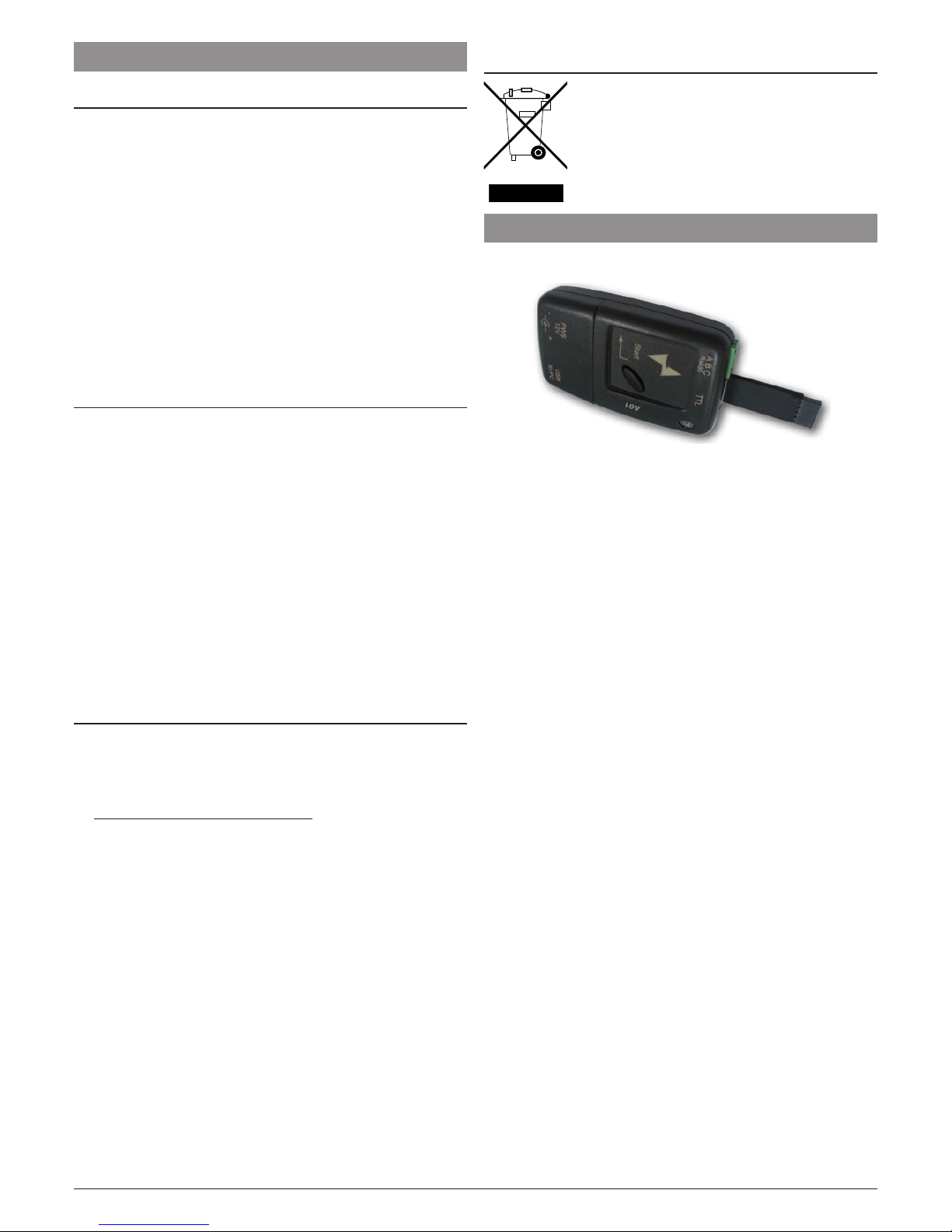
Ascon Tecnologic - KX6 - ENGINEERING MANUAL - PAG. 21
10 GENERAL NOTES
10.1 Proper use
Every possible use not described in this manual must be
consider as a improper use.
This instrument is in compliance with EN 61010-1 “Safety
requirements for electrical equipment for measurement,
control and laboratory use”; for this reason it could not be
used as a safety equipment.
Whenever a failure or a malfunction of the control device
may cause dangerous situations for persons, thing or
animals, please remember that the plant has to be equipped
with additional safety devices.
Ascon Tecnologic S.r.l. and its legal representatives do not
assume any responsibility for any damage to people, things
or animals deriving from violation, wrong or improper use or
in any case not in compliance with the instrument’s features.
10.2 Warranty
This product is under warranty against manufacturing
defects or faulty materials that are found within 18 months
from delivery date. The warranty is limited to repairs or to the
replacement of the instrument.
The tampering of the instrument or an improper use of the
product will bring about the immediate withdrawal of the
warranty effects.
In the event of a faulty instrument, either within the period
of warranty, or further to its expiry, please contact our
sales department to obtain authorisation for sending the
instrument to our company.
The faulty product must be shipped to Ascon Tecnologic
with a detailed description of the faults found, without any
fees or charge for Ascon Tecnologic, except in the event of
alternative agreements.
10.3 Maintenance
This instrument does not requires periodical recalibration
and it have no consumable parts so that no particular
maintenance is required.
Sometimes it is advisable to clean the instrument.
1. SWITCH THE EQUIPMENT OFF
(power supply, relay output, etc.).
2. Using a vacuum cleaner or a compressed air jet (max. 3
kg/cm2) remove all deposits of dust and dirt which may
be present on the case and on the internal circuits being
careful not to damage the electronic components.
3. To clean external plastic or rubber parts use only a cloth
moistened with:
• Ethyl Alcohol (pure or denatured) [C2H5OH] or
• Isopropyl Alcohol (pure or denatured) [(CH3)2CHOH]
or
• Water (H2O).
4. Make sure that there are no loose terminals.
5. Before turning ON the instrument make sure it is perfectly
dry.
6. Apply the power supply to the instrument.
10.4 Disposal
The appliance (or the product) must be
disposed of separately in compliance
with the local standards in force on
waste disposal.
11 ACCESSORIES
The instrument has a lateral socket into which a special
tool can be inserted.
This tool, named A01, allows:
– To store a complete instrument configuration and to use it
for other instruments.
– To transfer a complete instrument configuration to a PC or
from a PC to an instrument
– To transfer from a PC to an instrument a complete
instrument configuration
– To transfer a configuration from an A01 to another one.
– To test serial interface of the instruments and to help the
OEM during machine start up.
Note: When the instrument is powered by the A01 key, the
outputs are NOT supplied.
Page 22

Ascon Tecnologic - KX6 - ENGINEERING MANUAL - PAG. 22
Appendix A
]
inP GROUP - Main and auxiliary input configuration
no. Param. Description
Dec.
Point
Values Default
1
SEnS
Input type 0
J TC J (-50... +1000°C/-58... +1832°F);
crAL TC K (-50... +1370°C/-58... +2498°F);
S TC S (-50... 1760°C/-58... +3200°F);
r TC R (-50... +1760°C/-58... +3200);
t TC T (-70... +400°C/-94... +752°F);
0.20 0... 20 mA linear;
4.20 4... 20 mA linear;
0.60 0... 60 mV linear;
12.60 12... 60 mA linear.
J
2
dp
Decimal Point Position (linear inputs) 0 0... 3 0
3
SSc
Initial scale read-out for linear inputs dp -1999... 9999 0
4
FSc
Full Scale Readout for linear inputs dp -1999... 9999 1000
5
unit
Engineer unit °C/°F °C
6
Fil
Digital filter on the measured value 1 0 (= OFF) - 0.1... 20.0 s 1.0
7
inE
Sensor error used to enable the safety output value
or Over range;
ou Under range;
our Over and under range.
our
8
oPE
Safety output value (% of the output) -100... 100% of the oputput 0
9
diF1
Digital Input 1 function
oFF No function;
1 Alarm reset;
2 Alarm acknowledge (ACK);
3 Hold of the measured value;
4 Stand by mode;
5 Manual mode;
6 HEAt with SP1 and CooL with SP2;
7 SP1 - SP2 selection.
oFF
10
diF2
Digital Input 2 function oFF
11
di.A
Digital Inputs Action
(DI2 only if configured)
0 DI1 direct action, DI2 direct action;
1 DI1 reverse action, DI2 direct action;
2 DI1 direct action, DI2 reverse action;
3 DI1 reverse action, DI2 reverse action.
0
]
Out group
no. Param. Description
Dec.
Point
Values Default
12
o1t
Output 1 type
(when Out 1 is a linear output)
0-20 0... 20 mA;
4-20 4... 20 mA;
0-10 0... 10 V;
2-10 2... 10 V.
0-20
13
o1F
Out 1 function
(when Out 1 is a digital output)
NonE Output not used;
H.rEG Heating output;
c.rEG Cooling output.
H.rEG
14
o2F
Out 2 function (when the instrument is
equipped with 2 digital output)
NonE Output not used;
H.rEG Heating output;
c.rEG Cooling output.
15
o3AL
Alarms linked up with Out 3 0
0... 31:
+1 Alarm 1;
+2 Alarm 2;
+4 Loop break alarm;
+8 Sensor break;
+16 Potentiometer break alarm.
AL2
16
o3Ac
Out 3 action 0
dir Direct action;
rEU Reverse action;
dir.r Direct with reversed LED;
ReU.r Reverse with reversed LED.
dir
17
o4AL
Alarms linked up with the out 4 0
0... 31:
+1 Alarm 1;
+2 Alarm 2;
+4 Loop break alarm;
+8 Sensor break;
+16 Potentiometer break alarm.
AL1 +
AL2
18
o4Ac
Out 4 action 0
dir Direct action;
rEU Reverse action;
dir.r Direct with reversed LED;
ReU.r Reverse with reversed LED.
dir
Page 23

Ascon Tecnologic - KX6 - ENGINEERING MANUAL - PAG. 23
]
AL1 group
no. Param. Description
Dec.
Point
Values Default
19
AL1t
Alarm 1 type 0
nonE Alarm not used;
LoAb Absolute low alarm;
HiAb Absolute high alarm;
LHAo Windows alarm in alarm outside the windows;
LHAi Windows alarm in alarm inside the windows;
SE.br Sensor Break;
LodE Deviation low alarm (relative);
HidE Deviation high alarm (relative);
LHdo Relative band alarm in alarm out of the band;
LHdi Relative band alarm in alarm inside the band.
HiAb
20
Ab1
Alarm 1 function 0
0... 15:
+1 Not active at power up;
+2 Latched alarm (manual reset);
+4 Acknowledgeable alarm;
+8
Relative alarm not active at set point change.
0
21
AL1L
- For High and low alarms, it is the low limit
of the AL1 threshold;
- For band alarm, it is low alarm threshold
dp From -1999 to AL1H (E.U.) -1999
22
AL1H
- For High and low alarms, it is the high
limit of the AL1 threshold;
- For band alarm, it is high alarm threshold
dp From AL1L to 9999 (E.U.) 9999
23
AL1
AL1 threshold dp From AL1L to AL1H (E.U.) 0
24
HAL1
AL1 hysteresis dp 1... 9999 (E.U.) 1
25
AL1d
AL1 delay 0 From 0 (oFF) to 9999 (s) oFF
26
AL1o
Alarm 1 enabling during Stand-by mode and
out of range conditions
0
0 Alarm 1 disabled during Stand by and out of range;
1 Alarm 1 enabled in stand by mode;
2 Alarm 1 enabled in out of range condition;
3 Alarm 1 enabled in stand by mode and in out of
range condition.
0
]
AL2 group
no. Param. Description
Dec.
Point
Values Default
27
AL2t
Alarm 2 type 0
nonE Alarm not used;
LoAb Absolute low alarm;
HiAb Absolute high alarm;
LHAo Windows alarm in alarm outside the windows;
LHAi Windows alarm in alarm inside the windows;
SE.br Sensor Break;
LodE Deviation low alarm (relative);
HidE Deviation high alarm (relative);
LHdo Relative band alarm in alarm out of the band;
LHdi Relative band alarm in alarm inside the band.
Loab
28
Ab2
Alarm 2 function 0
0... 15:
+1 Not active at power up;
+2 Latched alarm (manual reset);
+4 Acknowledgeable alarm;
+8
Relative alarm not active at set point change
0
29
AL2L
- For High and low alarms, it is the low limit
of the AL2 threshold;
- For band alarm, it is low alarm threshold
dp From -1999 to AL2H (E.U.) -1999
30
AL2H
- For High and low alarms, it is the high
limit of the AL2 threshold;
- For band alarm, it is high alarm threshold
dp From AL2L to 9999 (E.U.) 9999
31
AL2
AL2 threshold dp From AL2L to AL2H (E.U.) 0
32
HAL2
AL2 hysteresis dp 1... 9999 (E.U.) 1
33
AL2d
AL2 delay 0 From 0 (oFF) to 9999 (s) oFF
34
AL2o
Alarm 2 enabling during Stand-by mode and
out of range conditions
0
0 Alarm 2 disabled during Stand by and out of range;
1 Alarm 2 enabled in stand by mode;
2 Alarm 2 enabled in out of range condition;
3 Alarm 2 enabled in stand by mode and in out of
range condition.
0
Page 24

Ascon Tecnologic - KX6 - ENGINEERING MANUAL - PAG. 24
]
LBA group - Loop Break Alarm Parameters
no. Param. Description
Dec.
Point
Values Default
35
LbAt
LBA time 0 From 0 (oFF) to 9999 (s) oFF
36
LbSt
Delta measure used by LBA during Soft start dP From 0 (oFF) to 9999 (E.U.) 10
37
LbAS
Delta measure used by LBA dP 1...9999 (E.U.) 20
38
LbcA
Condition for LBA enabling 0
uP Active when Pout = 100%;
dn Active when Pout = -100%;
both Active in both cases.
both
]
rEG group - Control Parameters
no. Param. Description
Dec.
Point
Values Default
39
cont
Control type
(when the controller is equipped
with digital outputs)
Pid PID (Single or double action);
On.FA ON/OFF asymmetric (Single action);
On.FS ON/OFF symmetric (Single action);
nr ON/OFF double action with neutral zone;
3Pt Servomotor control (Out 1 = open, Out 2 = close).
40
Auto
Autotuning selection 0
-4 Oscillating auto-tune with automatic restart at power up and
after all point change;
-3 Oscillating auto-tune with manual start;
-2
Oscillating -tune with automatic start at the first power up only;
-1
Oscillating auto-tune with automatic restart at every power up;
0 Not used;
1 Fast auto tuning with automatic restart at every power up;
2 Fast auto-tune with automatic start the first power up only;
3 FAST auto-tune with manual start;
4 FAST auto-tune with automatic restart at power up and
after a set point change;
5 Evo-tune with automatic restart at every power up;
6 Evo-tune with automatic start the first power up only;
7 Evo-tune with manual start;
8 Evo-tune with automatic restart at power up and after a set
point change.
7
41
tunE
Manual start of the Autotuning 0
oFF Not active;
on Active
oFF
42
hSet
Hysteresis of the ON/OFF control dP 0... 9999 (E.U.)
43
Pb
Proportional band dP 1... 9999 (E.U.) 50
44
ti
Integral time 0 From 0 (oFF) to 9999 (s) 200
45
td
Derivative time 0 From 0 (oFF) to 9999 (s) 50
46
Fuoc
Fuzzy overshoot control 2 0.00... 2.00 0.50
47
tch
Heating output cycle time 1 0.1... 130.0 (s) 20.0
48
rcG
Power ratio between heating and
cooling action
2 0.01... 99.99 1.0
49
tcc
Cooling output cycle time 1 0.1... 130.0 (s) 20.0
50
rS
Manual reset (Integral pre-load) 1 -100.0... +100.0 (%) 0.0
51
Str.t
Servomotor stroke time 0 5... 300 seconds 60
52
db.S
Servomotor dead band 0 0...100% 50
53
oP.L
Minimum Power Output From 100 to OP.H%
54
oP.H
Maximum Power Output From OP.L to 100%
55
St.P
Maximum power output used during
soft start
0 -100... 100 (%) 0
56
SSt
Soft start time 2
0.00 oFF;
0.01... 7.59 (hh.mm);
inF Always ON.
oFF
57
SS.tH
Threshold for soft start disabling dP -1999... +9999 (E.U.) 9999
58
Pot
Potentiometer enabling
nonE Potentiometer not used;
Pot.o Potentiometer used for indication only;
Pot.c Potentiometer used for feedback control
59
P.caL
Automatic potentiometer calibration
no The automatic potentiometer calibration is disabled;
YES The automatic potentiometer calibration is enabled.
Page 25
Ascon Tecnologic - KX6 - ENGINEERING MANUAL - PAG. 25
]
SP group - Set point parameters
no. Param. Description
Dec.
Point
Values Default
60
nSP
Number of used set points 0 1... 4 1
61
SPLL
Minimum set point value dP From -1999 to SPHL -1999
62
SPHL
Maximum set point value dP From SPLL to 9999 9999
63
SP
Set point 1 dP From SPLL to SPLH 0
64
SP2
Set point 2 dP From SPLL to SPLH 0
65
SP3
Set point 3 dP From SPLL to SPLH 0
66
SP4
Set point 4 dP From SPLL to SPLH 0
67
A.SP
Selection of the active set point 0 From 1 (SP 1) to nSP 1
68
SP.rt
Remote set point type 0
rSP The value coming from serial link is used as remote SP;
trin The value will be added to the local set point selected
by A.SP and the sum becomes the operative set point;
PErc The value will be scaled on the input range and this
value will be used as remote SP.
trin
69
SPLr
Local/remote set point selection 0
Loc Local;
rEn = Remote.
Loc
70
SP.u
Rate of rise for POSITIVE set point
change (ramp UP)
2 0.01... 99.99 (inF) engineering units per minute inF
71
SP.d
Rate of rise for NEGATIVE set point
change (ramp DOWN)
2 0.01... 99.99 (inF) engineering units per minute inF
]
PAn group - Operator HMI parameters
no. Param. Description
Dec.
Point
Values Default
72
PAS2
Level 2 password (limited
access level)
0
oFF Level 2 not protected by password;
1... 200.
20
73
PAS3
Level 3 password (complete configuration level)
0 3... 200 30
74
uSrb
button function during
RUN TIME
nonE No function;
tunE Auto-tune/self-tune enabling. A single press (longer than 1 se-
cond) starts the auto-tune;
oPLo
Manual mode. The first pressure puts the instrument in manual mode
(oPLo) while a second one puts the instrument in Auto mode;
AAc Alarm acknowledge;
ASi Alarm reset;
St.by
Stand by mode. The first press puts the instrument in stand by
mode while a second one puts the instrument in Auto mode
t;
SP1.2 SP/SP2 selection.
tunE
75
diSP
Middle display management
nonE Standard display;
SPF Final set point;
Spo Operative set point;
AL1 Alarm 1 threshold;
AL2 Alarm 2 threshold;
Po Power Output
0
76
di.cL
Colour of the upper display
0 The display colour is used to show the actual deviation (PV - SP);
1 Display red;
2 Display green;
3 Display orange.
0
77
AdE
Deviation for display colour
management
1... 9999 (E.U.) 5
78
diS.t
Display Timeout 2
oFF Display always ON;
0.1... 99.59 (mm.ss).
oFF
79
fiLd
Filter on the displayed
value
1
oFF Filter disabled;
1... 100 (E.U.).
oFF
80
dSPu
Instrument status at power
ON
AS.Pr Starts in the same way it was prior to the power down;
Auto Starts in Auto mode;
oP.0 Starts in manual mode with a power output equal to zero;
St.bY Starts in stand-by mode.
AS.Pr
81
oPr.E
Operative modes enabling
ALL All modes will be selectable by the next parameter;
Au.oP Auto and manual (oPLo) mode only will be selectable by the next
parameter;
Au.Sb
Auto and Stand-by modes only will be selectable by the next parameter
ALL
82
oPEr
Operative mode selection
If oPr.E = ALL: - Auto = Auto mode;
- oPLo = Manual mode;
- St.bY = Stand by mode;
If oPr.E = Au.oP:
- Auto = Auto mode;
- oPLo = Manual mode;
If oPr.E = Au.Sb: - Auto = Auto mode;
- St.bY = Stand by mode.
Auto
Page 26

Ascon Tecnologic - KX6 - ENGINEERING MANUAL - PAG. 26
]
Ser group - Serial link parameters
no. Param. Description
Dec.
Point
Values Default
83
Add
Instrument address
oFF Serial link disabled;
1... 254.
1
84
bAud
Baud rate
1200 1200 baud;
2400 2400 baud;
9600 9600 baud;
19.2 19200 baud;
38.4 38400 baud
9600
85
trSP
Selection of the value to
be retransmitted (Master)
nonE Retransmission not used (the instrument is a slave);
rSP The instrument becomes a Master and retransmits the operative set
point;
PErc
The instrument become a Master and it retransmits the power output
nonE
]
cAL group - User calibration parameters
no. Param. Description
Dec.
Point
Values Default
86
AL.P
Adjust Low Point From -1999 to (AH.P - 10) in engineering units 0
87
AL.o
Adjust Low Offset -300... +300 (E.U.) 0
88
AH.P
Adjust High Point From (AL.P + 10) to 9999 engineering units 9999
89
AH.o
Adjust High Offset -300... +300 0
Page 27

Ascon Tecnologic - KX6 - ENGINEERING MANUAL - PAG. 27
Page 28

Ascon Tecnologic - KX6 - ENGINEERING MANUAL - PAG. 28
 Loading...