

Ascon Tecnologic - e33 - OPERATING INSTRUCTIONS - PAG. 1
e33
DIGITAL ELECTRONIC
TEMPERATURE CONTROLLER
WITH DEFROSTING FUNCTION
OPERATING INSTRUCTIONS
Vr 01 (ENG) - 17/06 - cod.: ISTR-Me33ENG01
ASCON TECNOLOGIC S.r.l.
Viale Indipendenza 56, 27029 - VIGEVANO (PV) ITALY
Tel.: +39 0381 69871 - Fax: +39 0381 698730
http:\\www.ascontecnologic.com
info@ascontecnologic.com
PREFACE
This manual contains the information necessary for
the product to be installed correctly and also instructions for its maintenance and use; we therefore recommend that the utmost attention is paid to the following
instructions and to save it
This document is the exclusive property of Ascon Tecnologic
S.r.l. which forbids any reproduction and divulgation, even
partially, of the document, unless expressly authorized.
Ascon Tecnologic
S.r.l. reserves the right to make any formal
or functional changes at any moment and without any notice.
Ascon Tecnologic S.r.l. and its legal representatives do not
assume any responsibility for any damage to people, things
or animals deriving from violation, wrong or improper use or
in any case not in compliance with the instrument features.
Whenever a failure or a malfunction of the device
may cause dangerous situations for persons, thing
or animals, please remember that the plant has to be
equipped with additional electromechanical devices
which will guarantee safety.
1. INSTRUMENT DESCRIPTION
1.1 General description
The model e33 is a microprocessor based digital electronic
temperature controller that is typically used in cooling applications with ON/OFF temperature control and defrost
control at time intervals, by arrival at temperature or by
length of time of continuous compressor operation through
stopping the compressor, electric heating or hot gas/cycle
inversion.
The instrument has up to 3 relay outputs and up to 3 NTC
temperature probes inputs one of which can be configured as digital input; it can also be equipped with a built-in
buzzer for alarms acoustic report.
Index
1. Instrument description ............................................... 1
1.1 General description ........................................................... 1
1.2 Front panel pescription .....................................................2
2. Programming ............................................................... 2
2.1 Fast Set Point programming ..............................................2
2.2 Standard mode parameters programming ........................ 2
2.3 Parameter protection using the password ......................... 3
2.4 Customized mode parameter programming (parameters
programming level) ...........................................................3
2.5 Reset parameters to default value ....................................3
2.6 Keyboard lock function ...................................................... 3
3. Usage warnings ........................................................... 3
3.1 Admitted use ..................................................................... 3
4. Installation warnings ................................................... 4
4.1 Mechanical mounting ........................................................ 4
4.2 Electrical connections ....................................................... 4
5. Functions ..................................................................... 5
5.1 ON/Stand-by function ........................................................5
5.2 Normal, Economic and Turbo operation ............................ 5
5.3 Measure and display configuration ...................................5
5.4 Digital input configuration .................................................. 6
5.5 Outputs and buzzer configuration ..................................... 6
5.6 Temperature control .......................................................... 7
5.7 Compressor protection function and power-on delay ........ 8
5.8 Defrost control ................................................................... 8
5.9 Evaporator fans control ...................................................10
5.10 Alarm functions ............................................................... 10
5.11 Function of keys / and /Aux ................................ 12
6. Accessories ............................................................... 12
6.1 Parameters configuration by “A01” ..................................12
7. Programmable parameters table .............................. 13
8. Problems, maintenance and warranty ..................... 16
8.1 Notifications .................................................................... 16
8.2 Cleaning .......................................................................... 16
8.3 Warranty and Repairs .....................................................16
8.4 Disposal .......................................................................... 16
9. Technical data ............................................................ 16
9.1 Electrical characteristics ................................................. 16
9.2 Mechanical characteristics .............................................. 16
9.3 Functional features .........................................................17
10. Instrument ordering code ......................................... 17

Ascon Tecnologic - e33 - OPERATING INSTRUCTIONS - PAG. 2
1.2 Front panel pescription
e33
P
U
Aux
1
2
3
4
5
9
7
8
10
6
1 : Used for setting the Set Point (short press) and for
programming the function parameters (pressed for 5 s).
In programming mode is used to enter in parameters edit
mode and confirm the values. In programming mode
can be used together with the key to change the programming level of the parameters. When the keyboard is
locked, the keys and used together (hold pressed
for 5 s), unlock the keyboard.
2 /Aux: In programming mode is used for decreasing
the values to be set and for selecting the parameters. If
programmed using the tFb parameter, when it is pressed
for 1 s during normal operation mode, it can perform other
functions such as Eco mode selectionf, Aux output control
etc. (see “Functions of keys
/
and /Aux”).
3 / : In normal mode (pressed for 5 s) can be used
to start/stop manual defrosting ( ). In programming
mode is used for increasing the values to be set and for
selecting the parameters. In programming mode can be
used together with key to change parameters level.
Pressed together with the key for 5 s allows the keyboard unlock.
4 / : Used (short press) for displaying the instrument
variables (measured temperatures etc.). In programming
mode can be used to return in normal mode (hold for 2 s).
If programmed using the tUf parameter, when it is
pressed for 1 s during normal operation mode allows
to turn ON/OFF (Stand by) the control action or other
functions like the Aux input control etc. (see “
Functions of
keys
/
and /Aux
”).
5 LED dp: Decimal Point, when the instrument is placed in
Stand by mode, this is the only lighted LED. During the
normal operation is the decimal point. In programming
mode, while the parameter code is displayed, the dot
indicates the parameter protection level: not protected
(lit up), protected (flashing) and hidden (turned OFF).
6 LED : Indicates the output status (compressor or
temperature control device) when the instrument
is programmed for cooling operation; ON (lit up),
OFF (turned OFF) or inhibited (flashing).
7 LED : Indicates the output status (compressor or temper-
ature control device) when the instrument is programmed
for heating operation; ON (lit), OFF (turned OFF) or inhib-
ited (flashing).
8 LED : Indicates the alarm status: ON (lit),
OFF (turned OFF) or silenced or stored (flashing).
9 LED : Indicates that the defrost is in progress (on) or
drainage time in progress (flashing).
10 LED : Indicates fan output status ON (on), OFF (off)
or inhibited (flashing).
2. PROGRAMMING
2.1 Fast Set Point programming
The normal mode to program the setpoint is done by momentarily pressing the key, the display shows SP (or SPE)
alternated to the programmed value.
To change it press the key to increase the value or to
decrease it.
These keys increase or decrease the value one digit at a time,
but if the button is pressed for more than one second the value
increase or decreases rapidly and after two seconds the speed
increases even more in order to quickly reach the desired value.
However, through ted parameter you can determine if and
which Set Point can be set with the key rapid procedure.
The parameter can have the following values:
oF The Set Points cannot be changed with the key rapid
procedure (pressing/releasing the key, nothing happens);
1
Only SP can be set with this procedure (Normal Set Point);
2 Only SPE can be set with this procedure (Eco Set Point);
3 Both SP and SPE can be set with this procedure;
4 To select the Active Set Point (SP or SPE);
5 Both SP and SPH can be set with this procedure (SPH:
Set Point Turbo or independent Heating Set Point);
6 All the 3 Set Points (SP/SPE/SPH) can be set with this
procedure.
For example, in case the parameter TEd = 1 or 3, the procedure is the following:
Press and release the key, the display shows SP alternated to the Set Point value. To change the Set Point, press
the key to increase the value or to decrease it
If only Set Point 1 is present (TEd = 1), once the desired value
is set, press the button to exit the fast programming mode.
If also the Eco Set Point (TEd = 3) can be set, pressing and
releasing again the button the display shows SPE alternated to its programmed value. To change the value use
the and keys as for the SP Set Point value. Once the
desired value is correctly set, press the button to exit the
fast Set Point change.
For SPH (TEd = 5 or 6) the procedure is the same of the one
used for SPE.
To exit the fast Setpoint programming mode push the
key after the last Set Point has been displayed or pressing
no buttons for about 10 s, after which the display returns to
normal operation.
2.2 Standard mode parameters programming
To access the instrument function parameters when password protection is disabled, press the key and keep it
pressed for about 5 seconds, after which the display shows
the code that identifies the first programmable parameter
The desired parameter can be selected using the / keys,
then, pressing the key, the display shows the parameter
code alternated to its value that can be changed with the
and keys.
Once the desired value has been set, press the key
again: the new value is stored and the display shows only
the code of the selected parameter
Pressing the and keys, it is possible to select another
parameter and change it as described.

Ascon Tecnologic - e33 - OPERATING INSTRUCTIONS - PAG. 3
To exit the programming mode, press no keys for about 30 s
or keep the key pressed for 2 s.
Previous
Param.
Normal
mode
Parameter select
(Program mode)
Parameters set
Next
Param.
2 s
5 s
Increase
value
Decrease
value
-25.5
sLs -30.0
2.3 Parameter protection using the password
The instrument has a parameter protection function using a
password that can be personalised through the tPP parameter
To protect the parameters, set the desired password number
in the parameter tPP.
When the protection is active, press the key to access
the parameters and keep it pressed for about 5 s, after which
the display shows r.p.
Press the key, the display shows 0, using the / keys,
insert the programmed password number and press the key
again.
If the password is correct the instrument displays the code of
the first parameter and it will be possible to program the instrument in the same way described in the previous section.
The password protection can be disabled by setting tPP = oF.
Normal
mode
2 s
5 s
Increase
value
Decrease
value
-25.5
rp 0
sls
Note: If the Password gets lost, just switch OFF and ON the
instrument, push key during the initial test keeping
it pressed for 5 s. In this way it is possible to access all
the parameters, verify and modify the parameter tPP.
2.4 Customized mode parameter programming
(parameters programming level)
The password hides all the configuration parameters behind a
factory set password to avoid unwanted changes to the controller parameters.
To make a parameter accessible without
having to enter the password when tPP password protection
is activate, use the procedure that follows:
Enter the program mode using the tPP Password and select the
parameter that must be accessible (no password protection).
Once a parameter is selected, if the dp LED flashes the
parameter is programmable by entering the password (is
“protected”). If the dp LED is steady ON the parameter is
programmable without password (is “unprotected”).
To change the parameter visibility, press the key and
keeping it pressed also press the button.
The dp LED changes its state indicating the new level of
parameter accessibility (ON = not protected;
flashing = password protected).
In case some parameters are not protected, accessing
the the programming mode the display first shows the not
protected parameters, then the r.p parameter (through which
will be possible to access the “protected” parameters).
Normal
mode
2 s
5 s
Increase
value
Decrease
value
-25.5
r.p
Previous
Param.
Not protected
parameter
Parameters set
Password
request
Insert
password
Password OK,
Program Mode
Next
Param.
Increase
value
Decrease
value
AHA 35.0
0 sls
2.5 Reset parameters to default value
The instrument allows the reset of the parameters to values
programmed in factory as default
To restore the default parameters value set value -48 at r.p
password request Therefore, to make the reset to the default
parameters, enable the Password using the tPP parameter
so that the r.p setting is requested, at this point insert -48
instead of the programmed access password.
Once confirmed the password with the key the display
shows “---” for 2 s therefore the instrument resets all the
parameters to factory default setting.
2.6 Keyboard lock function
On the instrument it is possible to completely lock the keyboard.
This function is useful when the controller is in an accessible
area and the changes must be avoided.
To activate the keyboard lock it is enough program the pa-
rameter tLo to a value different from oF.
The
tLo
value is the keys inactivity time after which the key-
board will be automatically locked.
Therefore, pressing no buttons for the time set at tLo, the in-
strument automatically disable the normal functions of the keys.
When the keyboard is locked, if any of the key is pressed,
the display showss Ln to indicate that the lock is active.
To unlock the keyboard it is enough to contemporarily push
+ keys and keep them pushed for 5 s, after which the
label LF appears on the display and all the key functions will
be available again.
3. USAGE WARNINGS
3.1 Admitted use
The instrument has been projected and manufactured
as a measuring and control device to be used according to EN60730-1 at altitudes operation below 2000 m.
Using the instrument for applications not expressly permitted
by the above mentioned rule must adopt all the necessary
protective measures.
The instrument MUST NOT BE USED in dangerous environments (flammable or explosive) without adequate protections.
The instrument used with NTC 103AT11 probe (identifiable
by the printed code “103AT-11” visible on the sensor part)
is compliant with standard EN 13485 (“Thermometers for
measuring the air and product temperature for the transport,
storage and distribution of chilled, frozen, deep-frozen/quickfrozen food and ice cream”) with the following classification:

Ascon Tecnologic - e33 - OPERATING INSTRUCTIONS - PAG. 4
[EN13485 air, S, A, 2, -50°C +90°C]
Remember that the end user must periodically check and veri-
fy the thermometers in compliance with standard EN 13486.
The installer must ensure that the EMC rules are respected,
also after the instrument installation, if necessary using
proper filters.
4. INSTALLATION WARNINGS
4.1 Mechanical mounting
The instrument, in case 78 x 35 mm, is designed for flushin panel mounting. Make a 71 x 29 mm hole and insert the
instrument, fixing it with the provided special brackets.
In order to obtain the declared front protection degree, mount
the gasket and use the screw type bracket (both optional).
Avoid placing the instrument in environments with very high
humidity levels or dirt that may create condensation or introduction of conductive substances into the instrument
Ensure adequate ventilation to the instrument and avoid
installation in containers that house devices which may
overheat or which may cause the instrument to function at a
higher temperature than the one permitted and declared.
Connect the instrument as far away as possible from sources
of electromagnetic disturbances such as motors, power relays, relays, solenoid valves, etc..
4.1.1 Mechanical dimensions, panel cut-out and
mounting [mm]
35
28
12.2
14.5
8
6
6478
e33
P
U
Aux
29
+0.6
71
+0.6
mm
RECOMMENDED
PANEL CUTOUT
min. 12 mm
min. 15 mm
Panel + Gasket max. 12 mm
Brackets
34
4.2 Electrical connections
Carry out the electrical wiring by connecting only one wire to
each terminal, according to the following diagram, checking
that the power supply is the same as that indicated on the
instrument and that the load current absorption is no higher
than the maximum electricity current permitted.
As the instrument is built-in equipment with permanent connection inside housing, it is not equipped with either switches
or internal devices to protect against current overloads: the
installation will include an overload protection and a twophase circuit-breaker, placed as near as possible to the instrument and located in a position that can easily be reached
by the user and marked as instrument disconnecting device
which interrupts the power supply to the equipment
It is also recommended that the supply of all the electrical circuits connected to the instrument must be protect properly, using devices (ex. fuses) proportionate to the circulating currents.
It is strongly recommended that cables with proper insulation,
according to the working voltages and temperatures, be used.
Furthermore, the input cable of the probe has to be kept separate from line voltage wiring. If the input cable of the probe is
screened, it has to be connected to the ground at only one side.
Whether the instrument is a 12 V version (Power supply code
F) it is recommended to use an external TCTR transformer, or
with equivalent features (class II insulation) and to use only one
transformer for each instrument because there is no insulation
between supply and input
We recommend that a check should be made that the
parameters are those desired and that the application
functions correctly before connecting the outputs to
the actuators so as to avoid malfunctioning that may
cause irregularities in the plant that could cause damage to people, things or animals.
4.2.1 Electrical wiring diagram
Internal
Buzzer
Pr1 Pr3Pr2
Digital
Input
Power
supply
INPUTS
NO
NO
NONC
C
Out2
Out1
Out3
OUTPUTS
(12 A max. for removable connectors models)
16 FLA
96 LRA
15 A Res.
EN
30 (15) A
61810
Out 1 (H):
15 (15) A
5 FLA
30 LRA
12 A Res.16 (9) AOut 1 (R): 10 (4) A
10 A Res.8 (3) AOut 2: 8 (4) A
2 A Gen. Use5 (1) AOut 3: 2 (1) A
60730
EN UL

Ascon Tecnologic - e33 - OPERATING INSTRUCTIONS - PAG. 5
5. FUNCTIONS
5.1 ON/Stand-by function
Once powered the instrument can assume 2 different conditions:
ON: Means that the controller uses the control functions.
STAND-BY:
Means that the controller uses no control function and
the display is turned off except for the Stand-by LED.
The transition between Standby and ON is equivalent to
power ON the instrument providing the electrical power
In case of power failure, the system always sets itself in the
condition it was in before the black-out
The ON/Stand-by function can be selected:
– With the key / pressed for 1 s if tUF = 3;
– With the key /Aux pressed for 1 s if tfb = 3;
– Using the Digital Input if parameter iFi = 7;
5.2 Normal, Economic and Turbo operation
This tool allows to pre-set 3 different Setpoints, Normal - SP,
Economic (or Eco) - SPE and Turbo SPH.
Associated with each Setpoint there is the relative differential
(hysteresis): Normal - rd, Eco - rEd and Turbo - rHe. Switch-
ing between the various modes can be automatic or manual.
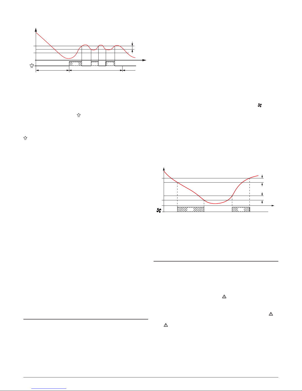
5.2.1 Normal/Eco operation selection
This function can be used when you need to switch two functional temperatures (eg. Day/Night or week-day/week-end).
SPE
SP
Door
rd
rEd
iEt
time“Norm.”
DAY (Shop open) DAY (Shop open)NIGHT (Shop closed)
“Norm.” “ECO”
The Normal/Eco operation can be selected in manual mode:
– Using the / key if parameter tUF = 2;
– Using the /Aux key if parameter tFb = 2;
– Using the Digital Input if parameter iFi = 6.
The Normal/Eco operation can be selected in automatic mode:
– Elapsed the iEt time after the door has been closed
(Normal/Eco switching).
– At door opening if the SPE Setpoint is activated by iEt
parameter (Eco/Normal switching).
– Elapsed the itt time after the door has been closed and
from the activation of SPE Setpoint by iEt parameter
(Eco/Normal switching).
To use this function, it is necessary to set the Digital Input as:
iFi = 1, 2 or 3.
If iEt = oF the selection of Eco/Normal modes via the digital
input is disabled.
If itt = oF the time-out switching from Eco to Normal mode
is disabled.
Switching to Economic mode is indicated by the label Eco.
When idS = Ec the Economic mode is pointed out with a
fixed Eco label otherwise the label Eco appears every 10 s
alternated to the display set with parameter idS.
When used as a shop widow light (oFo = 3), Eco mode
selection is always associated with the Auxiliary Output turn
OFF function.
5.2.2 Turbo/Normal/Eco operation selection
Turbo mode can be selected manually:
– Pressing the / key if parameter tUF = 4;
– Pressing the /Aux key if parameter tFb = 4;
– From digital input if parameter i.Fi = 8;
Turbo mode can be selected automatically:
– Leaving Eco mode (only if rHC = C3)
– Every time the instrument is switched ON (only if rHC = C3
and Pr1 > SPE + rEd)
The instrument quits Turbo mode and returns to normal mode
automatically at the end of rtC time or manually using the
programmed command (key or digital input).
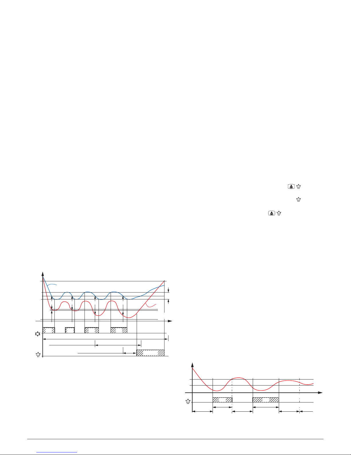
Setting rHC = C3 gives the following operating cycle:
At power ON, the instrument starts in the mode it was in
when it was switched OFF (Normal or “Eco”) unless the temperature at power ON is > SPE + rEd. In this case (see fig.)
a Turbo cycle is automatically initiated.
After time rtC the instrument automatically swiyches to Nor-
mal mode. If the door is opened frequently, the instrument
remains in Normal mode. If however the door is not opened
for time set at iEt parameter, it automatically switches to
Eco mode.
The instrument remains in Eco mode until the door is
opened again or, if set, until the time-out itt.
On leaving Eco mode the instrument therefore runs a Turbo
cycle to allow product temperature to be restored, after
which it reverts to Normal mode and so on.
Temp.
SPE
Eco
SP
SPH
Turbo
rHd
rEd
itt (2)
rtCrtC
time
Normal TurboECOTurbo
iEt (1)
rd
Pr1
1 The time iEt is reset every time the door is opened and
in the case shown the door is always closed.
2 The time itt stops when the door is opened and the
instrument immediately switches to Turbo mode. In the
case shown, the door is always closed.
When in Turbo mode, the instrument shows the characters
trb alternated to the normal display indication.
The normal Set Point SP can be set to a value between the
one set with parameter SLS and the one set with parameter
SHS while the Economic Set Point SPE can be set to a value
between the one set with parameter SP and the one set with
parameter SHS; the Turbo Set point (SHP) can be set to a
value between the one set with parameter SLS and the one
set with parameter Sp.
Note: In the following examples the Set Point is generally
indicated as SP and the differential as rd however the
instrument will act according to the Set Point and the
differential selected as active.
5.3 Measure and display configuration
With parameter iuP it is possible to select the temperature engineering unit and the desired measure resolution
(C0 = °C/1°; C1 = °C/0.1°; F0 = °F/1°; F1 = °F/0.1°).
The instrument allows the measure calibration, which can
be used to recalibrate the instrument according to applica-

Ascon Tecnologic - e33 - OPERATING INSTRUCTIONS - PAG. 6
tion needs, the calibration is made by using parameters iC1
(input Pr1), iC2 (Pr2 input) and iC3 (Pr3 input).
Parameters iP2 and/or iP2 allows to select the instrument
usage of Pr2/Pr3 measure as:
EP Evaporator probe: used to managing the defrost and
the evaporator fans (see relative functions).
Au Auxiliary probe;
DG Digital Input (see the Digital input functions).
If Pr2/Pr3 input is not used, set iP2/ip3 = oF.
Two inputs cannot set to perform the same function.
If two inputs are set to do the same function, this is done
only by the P2 input.
Using iFt parameter can be set a software filter for measuring the input values in order to decrease the sensibility to rapid
temperature changes (increasing the sampling time).
Through the idS parameter is possible to set the variable
normally displayed:
P1 Pr1 probe measurement;
P2 Pr2 probe measurement;
P3 Pr3 probe measurement;
SP Active Set Point;
EC
Pr1 probe measure if the instrument is in Normal mode,
the label Eco if the instrument is in (Eco mode);
OFF If the numerical display must be switched off (oF).
When one of the measures is displayed (idS = P1/P2/Ec)
the iCU parameter allows to set an offset that is to be applied
only to the displayed variable (all controls will always made
according to the correct temperature value, changed only by
the calibration parameters).
Regardless of what is set at idS parameter, all the measurement variables can be shown pressing the key.
The display alternately shows the code that identifies the
variable and its value. The variables are:
Pr1 Probe 1 measurement;
Pr2
Probe 2 measurement (on/oFF if Pr2 is a Digital input);
Pr3
Probe 3 measurement (on/oFF if Pr3 is a Digital input);
Lt Minimum stored Pr1 temperature;
Ht Maximum stored Pr1 temperature.
The Peak (min./max.) temperature values of Pr1 probe are
NOT stored in case of power failure. While the controller is
showing the peak values, these can be reset pressing the
key for 3 s. At the end of the key pressure, the display
shows “---” for an instant to indicate that the min./max. values have been erased and the new peak is the temperature
read in that moment.
The system exits the variable dosplay mode after 15 s from
the last
key pressure.
It is also noted that the Pr1 probe display can also be changed
by “Defrost display lock” function via the ddL parameter
(see the Defrost function).
5.4 Digital input configuration
The digital input function (available on terminal 12 or instead
of Pr2 input if ip2 = dg) is defined using the iFi parameter
and the action is delayed for the time programmed with parameter iti. The iFi parameter can be configured for the
following functions:
0 Digital input not active;
1 Cell door opening with NO contact: at input closure (and
after the iti) the instrument displays alternately oP and
the variable set at idS parameter. With this mode of
operation of the digital input activates also the time set
with parameter AoA elapsed which the alarm is activated
to warn that the door has been left open. In addition, at
door opening, the instrument returns to Normal operation if it was in Eco mode and the Eco mode activation
was enabled through parameter iEt;
2 Cell door opening with NO contact: Similar to iFi = 1
but with evaporator fans stop. In addition, at open door
alarm intervention (AoA), the fans are restarted;
3 Cell door opening with compressor and fan outputs lock
and NO contact: similar to iFi = 2 but with compressor
and fans lock. At open door alarm intervention (AoA)
both the fans and the compressor are re-activated.
4 External alarm signal with NO contact: at input closing
(and after the iti time) the alarm is activated and the
instrument alternately shows on the display: AL and the
variable set with parameter idS;
5 External alarm signal withall control outputs disabled and
NO contact: at input closing (and after the iti time) all
the control outputs are disabled, the alarm is activated
and the instrument alternately shows on the display: AL
and the variable set with parameter idS;
6 Normal/Eco mode selection with NO contact: at input
closing (and after the iti time) the instrument switches to
Economic operation mode. Opening the digital input, the
instrument returns in Normal operation mode.
7 Instrument On/Off (stand-by) selection with NO contact:
at input closing (and after the iti time) the instrument
is switched ON while it is placed in Stand-by mode when
the digital input is open;
8 Turbo cycle activation command with NO contact: at in-
put closing (and after the iti time) the instrument starts
a Turbo cycle;
-1, -2, -3, etc. - Features identical to the above but obtained
through a NC contact and a reversed logic operation.
5.5 Outputs and buzzer configuration
The instrument outputs can be configured by the relative
parameters oo1, oo2 and oo3.
The outputs can be configured for the following functions:
ot To control
the temperature control device (e.g. Compressor). To manage the cooling control device for neutral
zone control or Cooling/Heating (rHC = nr or HC);
df To control the defrosting device;
Fn To control the evaporator fans;
Au To control the auxiliary device;
At To control a silenceable alarm device through a contact
that is NO in normal operation then closed when the
alarm sounds;
AL To control an alarm that cannot be silenced through
a contact that is NO in normal operation then closed

Ascon Tecnologic - e33 - OPERATING INSTRUCTIONS - PAG. 7
when the alarm sounds;
An To control an alarm with a memory function through
a contact that is NO in normal operation then closed
when the alarm sounds (see alarm memory);
-t To control a silenceable alarm device through a con-
tact that is NC in normal operation then closed when
the alarm sounds;
-L Control an alarm that cannot be silenced through a
contact that is NC in normal operation then closed
when the alarm sounds;
-n To control an alarm with a memory function through
a contact that is NC in normal operation then closed
when the alarm sounds;
on To command a device that must be turned ON when
the instrument is ON. The output is therefore deactivated when the instrument is not powered or is in
standby mode. This mode of operation can be used
as a control of the shop window lighting, anti-fogging
resistors or other utilities;
HE To control a heating device in neutral zone or Cooling/
Heating control mode (rHC = nr or HC);
oF Output disabled.
If one of the outputs is configured as auxiliary output (oo1/oo2/
oo3 = Au), its function is set by parameter oFo and its operation can be conditioned by the time set to at parameter otu.
Parameter oFo can be configured for the following functions:
oF Auxiliary output not active;
1 Temperature control output delayed with NA contact:
the auxiliary output is activated with a delay that
can be set with parameter otu applied to the output
configured as ot. The output is then turned OFF at
the same time as the ot output is disabled. This function mode can be used as a command for a second
compressor or for all other working utilities according
to the same ot output conditions, but which must be
delayed after the start up of the compressor to avoid
excess electricity absorption;
2 Activation by front key ( or ): the output is ac-
tivated by pressing the keys or suitably configured (tUF or tFb = 1). These commands have a
bi-stable (toggle) function (at first pression the output is
activated, at the second is disabled). In this mode, the
Aux output can be turned OFF automatically after the
time set at parameter otu. When otu = oF the output
is activated and deactivated only manually, using the
or keys or via the digital input. Differently, the
output, once activated, is turned OFF automatically after the otu time. This mode of operation can be used
as a control of the shop window lighting, anti-fogging
resistors or other utilities;
3 Shop window light managed by Normal/Eco mode.
This output will be ON in Normal mode and OFF when
in Eco mode operation.
4 Internal Light output managed by digital input. This
output will be ON when door is opened (iFi = 1, 2, 3).
If present, the internal buzzer can be configured by parameter obu for the following functions:
oF Buzzer always disabled;
1 The Buzzer sounds when an alarm is active;
2 The Buzzer sounds when a key pressed (no alarm);
3 The Buzzer sounds when a key pressed and when an
alarm is active.
5.6 Temperature control
The instrument controls the temperature with an ON/OFF
action and operates on the outputs configured as ot and
HE depending on the PR1 probe measuring, the acive Set
Point/s SP/SPE/SPH, the Hysteresis rd/rEd/rHd and the
function mode set with rHC parameter. Using the rHC parameter can be obtained the functions that follow.
C Cooling;
H Heating.
SP
Temp.
rd
time
offoff
SP
rd
time
ON
rHC =
C
rHC =
H
offoffON ON ON ON ON
output
ot
output
ot
Pr1
Temp.
Pr1
Depending on the function mode programmed with parameter
rHC the differential is automatically considered by the controller with positive values for a Refrigeration control (rHC = C)
or negative values for a Heating control (rHC = H).
nr Neutral Zone
SP
off off
ON
Temp.
time
rd
rd
offoff
rHC
= nr
ON
ON
HE
ot
Outputs
Pr1
When rHC = nr, the output configured as ot operates with a
cooling action (like rHC = C) while the output configured as HE
operates with a heating action both with the active Set Point
(SP/SPE/SPH). The intervention differential (rd/rEd/rHd) is automatically assumed by the controller to have positive values for
the cooling action and negative values for the heating action.
HC
Cooling and Heating with independent Set Points
SP
SPH
off off off
Temp.
time
rd
rd
offoff
off
RHC = HC
ON ON ON
ONON
HE
ot
Pr1
Outputs
As in the previous case, when rHC = HC the output configured as ot operates with cooling action (like rHC = C) while
the output configured as HE operates with heating action.
In this case, however, the Set Point for the ot output is the
active one between SP, SPE or SPH, while for the HE output
the Set Point is SPH.
The intervention differential for the ot
output is the active between rd, rEd or rHd and is automatically assumed by the controller to have positive values for the
cooling action while for the output HE the differential is RHd
considered with negative values as for the Heating actions.
In this mode, the activation of the Turbo cycle causes the
instrument to operate with Neutral Zone and SPH set point.
The time protections described in the next paragraph (PP1/
PP2/PP3) always work on the output configured as ot and
have no effect on the HE output.
In the event of a probe error, it is possible to set the instru-

Ascon Tecnologic - e33 - OPERATING INSTRUCTIONS - PAG. 8
ment so that that the output continues to work in cycles
according to the times programmed with parameter rt1
(activation time) and rt2 (deactivation time).
If a Pr1 probe error occurs, the instrument can continue to
activate the ot output for rt1 time, then disables it for rt2
time and so on until the error persists.
By programming rt1 = oF the output, in probe error condition, will always be OFF. On the contrary, programming rt1
to any value and rt2 = oF the output, in probe error conditions, will always be on.
Remember that the operation of the temperature controller
can be conditioned by the following functions: Compressor
protection function and power-on delay, Defrost, Open door
and External alarm with output block from digital input.
5.7 Compressor protection function and
power-on delay
The “Compressor Protection” function aims to avoid repeated
compressor start-ups controlled by the instrument in cooling
applications or otherwise can be used to add a timed control
on the actuator control output
This function foresees 3 time controls on the switching ON of
the output configured as ot.
The protection consists of preventing the ot output being switched ON during the times set
with parameters PP1, pP2 and PP3 and therefore that any
activation occurs only after all times are elapsed.
1 First control (parameter PP1) foresees a delay to ot out-
put activation (switching-ON delay).
SP
Temp.
time
offoff off off
ON
ON
r.d
P.P1
P.P1
ot
ON
Pr1
Output
P.P1 P.P1
2 Second control (parameter PP2) foresees an inhibition to
the activation of the output by a time delay that starts when
the output is turning OFF (delay after switching-OFF).
offoff off
ON
SP
time
rd
PP2
ON ON
Temp.
ot
Pr1
Output
PP2 PP2 PP2
3 Third control (parameter PP3) foresees an inhibition to
the activation of the output by a time delay that starts
when the output was turned ON last time (delay between
two switching-ON).
offoffoff
ON
SP
time
rd
PP3
PP3 PP3
PP3
ON ON
Temp.
ot
Pr1
Output
During the output inhibition the LED OUT (Cool or Heat )
blinks. It is also possible to prevent activation of all the outputs
after the instrument is turned ON, for the time set in the parameter Pod.
During the power ON delay phase, the display shows the
indication od alternated with the normal visualization.
All these functions are disabled if the relative parameters are
set to OFF (oF).
5.8 Defrost control
The defrost control acts on the outputs configured as ot and dF.
The type of defrost is set by the parameter ddt:
EL With electrical heating (or By stopping compres-
sor): while defrosting, the output ot is deactivated
while the output dF is enabled. The defrost will be by
Stopping compressor if not using the dF output;
in With hot gas or Cycle inversion: while defrosting
both the ot and dF outputs are enabled:
no Without compressor output conditioning: while de-
frosting, the output ot continuous to operate in order to
control thetemperature, also the output dF is enabled;
Et With electrical heating and defrosting temperature
control: during defrosting, the output ot is deactivated
while the output dF operate as evaporator temperature
control. In this mode the defrost lenght is by time-out
(time ddE). During the defrost, the dF output behaves
as an heating mode control with Set Point = dtE, differential fixed at 1°C and operates with the values of
the EP evaporator probe.
5.8.1 Starting automatic defrosts
The automatic control of defrost occours:
– By interval times (regular or dynamic);
– By Evaporator temperature;
– By continuous compressor running time.
In order to avoid unnecessary defrosting when the evaporator temperature is high the dtS parameter allows to set the
temperature related to the evaporator probe (probe configured as EP) under which defrosts are possible.
Defrost by regular interval time
As an alternative to programmable defrosts, the instrument
allows to execute the defrosts at programmed interval time.
Through the ddC parameter, can be set the defrost interval
counting mode:
rt At real-time power-ON intervals. The ddi interval is
counted as the total ignition time of the instrument.
This mode is the one currently used in the refrigeration systems.
ct At time intervals of the compressor operation. The
ddi interval is counted as the sum of the operating
times of the ot output (ot output activated). This mode
is usually used in refrigeration systems with compressor stop defrosting.
cS Defrost cycle at each compressor stop. The instrument
starts a defrost cycle every time the ot output is deactivated, when the Set Point is reached or at the expiration of the interval set with ddi paramreter. If ddi =
oF the defrost happens only at compressor stop.
This mode is used only on particular refrigerating ma-
chines in which is required the maximum evaporator
efficiency at each compressor cycle.
To enable automatic defrost at intervals, after setting the ddC
parameter as desired between rt, ct or cS, with the ddi parameter select the time interval between the end of a defrost
and the beginning of the next.
The time that the instrument must wait to perform the first
defrost after power ON can be set with parameter dSd. This
allows to perform the first defrost to a different interval from
ddi time.
To force the instrument to perform a defrost cycle at each
Ascon Tecnologic - e33 - OPERATING INSTRUCTIONS - PAG. 9
power ON (as long as the conditions set with parameters
dtS and dtE are satisfied) set parameter dSd = oF.
This allows the evaporator to be permanently defrosted,
even when frequent interruptions to power supply occur that
may cause the cancellation of the various defrosting cycles.
If instead it is desired that all the defrosts are performed at
the same interval time, set dSd = ddi.
Setting ddi = oF the Automatic defrost function by interval
is totally disabled (including the first, regardless of the time
set to the dsd parameter).
Dynamic Defrost Intervals System
If ddd = 0 the Dynamic defrost is disabled.
Note: For this function is necessary to use the evaporator
probe.
To enable the Dynamic Defrost Intervals System, program
ddC = rt, ct or cS and set ddd = any value.
Setting ddd = 0, the defrost intervals are those set by the user
and the Dynamic Defrost Intervals System is disabled.
This mode allows to dynamically reduce the defrost interval
counting (ddi or dSd if is the first defrost), anticipating, when
necessary, the defrost execution, all based on an algorithm that
detects a drop in the refrigerator thermal exchange performance.
The algorithm estimates a reduction in thermal exchange
based on the increase in temperature difference between
Pr1 (cell control) and evaporator probe (probe configured as
EP). The result is stored by the instrument when the tem-
perature is close to the Set Point setting.
The advantage of the Dynamic Defrost Interval is the possi-
bility to program a defrost interval time longer than normal.
In this way, when necessary, the instrument has the pos-
sibility to anticipate the defrost or to start the cycle after the
programmed time.
If the system results correctly set, it is possible to avoid
many unnecessary defrosting cycles (and therefore to obtain
aconsistent energy saving) that may occur with normal operation when, to ensure more system efficiency, the defrosting interval is programmed with a time that is often too short.
Phase
off off
ON
01 2 3
Temp.
ddi/dSd time to defrost Phases 0, 1
Defrost
off off
DT0
dtE
dtS
Cool
ot
Defrost
dF
SP + rd
SP
Pr1
rd
EP
1°
DT1 DT2 DT3
time to defrost Phase 2
time to defrost Phase 3
time
ON ON ON
Example “dynamic defrost intervals system” with a reduction
ddd = 40% and end defrost by temperature.
With the parameter ddd - Defrost interval percentage reduc-
tion is possible to establish the percentage of reduction of
the remaining time to start defrost when the conditions for
the reduction happen.
If parameter ddd = 100% at the first increase of the stored
difference of temperature (> 1°) between cell (Pr1) and
evaporator (EP) probes a defrost starts immediately.
For correct functioning the instrument needs a first reference
value of the temperature difference between cell and evaporator, in this way all variations to the Active Set Point value, to
the differential rd, the start of a continuous cycle or a defrost
execution deletes this reference value and any reduction cannot be performed until the acquisition of a new reference value.
Defrost by evaporator temperature
The instrument starts a defrost cycle when the evaporator
temperature (EP probe) goes below the dtF programmed
temperature for dSt programmed time.
This system can be used to guarantee a defrost if the evaporator reaches very low temperatures that normally result
symptomatic of a bad thermal exchange in comparison to
the normal working conditions.
When dtF = -99.9 the function is disabled.
Defrost by continuous compressor running time
The instrument start a defrost cycle when the compressor is
turned ON continuously for the time dcd.
This function is used because the continuous operation for an
extended period of the compressor is usually symptomatic of
a bad thermal exchange in comparison to the normal working conditions.
When dcd = oF the function is disabled.
5.8.2 Manual defrost
To start a manual defrost cycle, press the key / when
in Normal operation mode and keep it pressed for about 5 s
after which, if the conditions are correct, the LED lights up
and the instrument performs a defrost cycle.
To stop a defrost cycle, press the key / during the defrost and keep it pressed for about 5 seconds.
5.8.3 End of defrosts
The defrost cycle duration can be time based, or, using the
evaporator probe (configured as EP) when a specific temperature is reached.
If the evaporator probe is not used or the thermostated
defrost mode is used (ddy = Et), the cycle length is set by
parameter dde.
If the Evaporator Probe (EP) is used and the thermostated
electric defrost is not selected (ddy = EL, in, no), the defrost
time occurs when the temperature measured by EP probe
exceeds the temperature at parameter DtE.
If this temperature is not reached in the time set in the parameter ddE, defrost cycle is interrupted.
To avoid unnecessary defrosting when the evaporator temperature is high in modes ddC = rt, ct, cS parameter DtS
allows to set the temperature related to the EP probe under
which defrosts are possible.
Therefore, in the indicated modes, if the temperature measured by the EP probe is higher than the one set at parameters dtS and also dtE the defrosting is inhibited.
dtE
dts
Defrost
dF
offoffoff
ON ON
AB
Temp.
time
C
(NO defrost)
dde
ddi/dSd
(Defrost)
ddi/dSd
ddi/dSd ddi
(Defrost)
EP
Example: Defrost A ends due to reaching of temperature
dtE, defrost B ends at the end of the ddE time as the
Ascon Tecnologic - e33 - OPERATING INSTRUCTIONS - PAG. 10
temperature dtE is not reached, defrosting C does not take
place as the temperature is higher than dts.
dtE
dts
offoffoff off
ddi/dSd
ON ON ON
time
ddi
(Defrost)
dde
1°
Defrost
dF
Temp.
EP
Example of electric defrost with evaporator temperature
control: the defrost end after ddE programmed time. During
defrost the dF output switch ON/OFF to control evaporator
temperature in heating mode with set point dtE and 1° differential (Hysteresis).
The active defrost is shown on the instrument display with
the lighting up of the LED .
At the end of defrosting, it is possible to delay the new compressor start up (output ot) at the time set in parameter dtd
to allow the evaporator to drain. During this delay, the LED
flashes to indicate the draining state.
5.8.4 Intervals and defrosts duration in case of
evaporator probe error
In event of evaporator probe error the defrosts occur at intervals dEi and duration dEE.
In case an error occurs when the time remaining to the start
or the end of defrost is lower than the one normally set with
the parameters related to error probe conditions, the start or
the end takes place with the shortest time.
These functions are provided because when the EP evaporator probe is used, the set defrost endurance time is usually
longer than necessary (the time ddE is a security time-out)
and in case is used the “Dynamic Intervals Defrost System”
the interval is usually set more longer than what is normally
programmed into instruments that do not have the function.
5.8.5 Display lock during Defrost
Through parameters ddL and AdA it is possible to define the
display behaviour during defrost:
on The ddL parameter locks the display at the last tem-
perature reading during all the defrost cycle until, at
the end of defrost, the temperature has not reached
the lock value or the value [SP + rd] or is elapsed the
time set at parameter AdA
Lb Shows the label dEF during the defrost cycle and PdF
after the defrost until, at the end of defrost, the temperature has not reached the lock value or the value
[SP + rd] or is elapsed the time set on parameter AdA
oF The display continues showing the temperature meas-
ured by the Pr1 probe during the defrost cycle.
5.9 Evaporator fans control
The control of the evaporator fans on the output configured as
Fn depends on some specific control statuses of the instrument
and the temperature measured by the evaporator probe (EP).
In the case that the evaporator probe is not used or in error,
the Fn output is activated only depending on parameters
Ftn, FtF and FFE.
Parameters Ftn and FtF can be used to determine the behavior
of the evaporator fans when the ot outupt (compressor) is OFF.
When ot output is OFF, it is possible to set the instrument so
that that the Fn output continues working in cycles according
to the times programmed at parameters Ftn (fan activation
time) and FtF (fan deactivation time).
When output ot is switched OFF the instrument activates the
output Fn for the time Ftn, then deactivates it for the time
FtF and so on whilst the otuput ot remains OFF.
Programming Ftn = oF the output Fn in ot OFF condition
remains switched OFF.
Programming instead Ftn to any value and FtF = oF the
output Fn when ot in OFF condition remains switched ON.
The parameter FFE decides whether the fans must always
be switched ON independently of the defrosting status
(FFE = on) or switched OFF during defrosting (FFE = oF).
In this later case, it is possible to delay the start up of the
fans even after the end of the defrosting of the time set in the
parameter FFd. When this delay is active the LED flashing to point out that the delay is in progress.
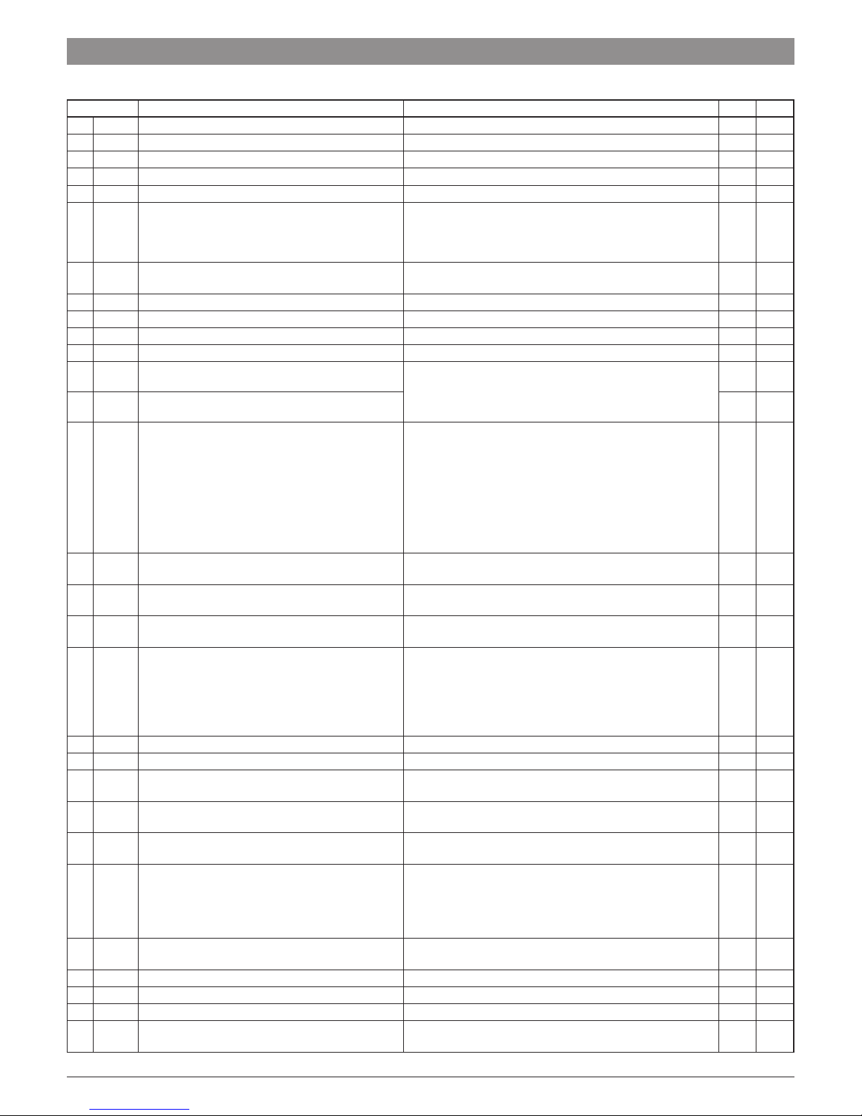
When the evaporator probe is used the fans, as well as being conditioned by the parameters Ftn, FtF and FFE, are
also conditioned by a temperature control.
It is possible to determine whether the fans should be disabled
when the temperature measured by the evaporator probe is
higher than the FFL parameter (too hot) or even when it is
lower than the FLF parameter (too cold).
The relative differential that can be set in parameter FdF is
also associated with these parameters.
FLF
FFL
Temp.
FdF
FdF
time
offoff offON ON
Ep
Fan
Note: It is necessary to pay attention to the correct use of
this fans temperature control functions because in
the typical application of refrigeration the stop of the
evaporator fans stops also the thermal exchange.
Remember that the fans functioning can be conditioned by
the Door open function by the digital input.
5.10 Alarm functions
The alarm conditions of the instrument are:
– Probe errors E1, -E1, E2, -E2 and E3, -E3;
– Temperature alarms Hi and Lo;
– External alarm AL;
– Door open oP.
The alarm functions acts on LED , on the internal buzzer,
if present and configured by the obu parameter and on the
desired output if configured by parameters oo1, oo2 or oo3.
Any active alarm condition is signaled lighting up the LED ,
while the acknowledged alarm status is shown by flashing the
LED .
The buzzer (if present) can be configured to point out the alarms
by programming parameter obu = 1 or 3 and always acts to
signal the acknowlegeable alarms. This means that, when
activated, it can be switched OFF by briefly pressing any key.
The possible selections of output parameters for the alarm
signalling function are:
At
When the output is to be activated in alarm condition

Ascon Tecnologic - e33 - OPERATING INSTRUCTIONS - PAG. 11
and can be deactivated manually by pressing any key of
the instrument (typical application for an acoustic signal);
AL When the output is to be activated in alarm condition
but cannot be deactivated manually; it is then deactivated only when the alarm status ceases (typical
application for a light signal);
An When the output is to be activated in alarm condi-
tion and that remains active even when the alarm
status has ceased. The disabling action (recognition
of stored alarm) can only be carried out manually by
pressing any key when the alarm status has removed
(typical application for light signal).
-t when one wants the function described as At but with
an inverse function (output activated in normal condition and disabled in alarm status).
-L This alarm function is similar to AL but with inverse
logic (output active in normal conditions and disabled
in alarm status).
-n This alarm function is similar to An but with inverse
working logic (output active in normal conditions and
disabled in alarm status).
The instrument offers the possibility to have the alarm
memory function activated via the parameter AtA.
If AtA = oF, the instrument cancels the alarm signal when
the alarm status ends, if instead AtA = on, the instrument
maintains the alarm signal also when the alarm status ends.
To cancel the alarm memory signal, press any key.
It must be remembered that if an output function is desired
with an alarm memory (oo1/oo2/oo3 = An/-An) it is
necessary to set the parameter AtA = on.
5.10.1 Temperature alarms
The temperature alarm works according to Pr1 or AU probes
measurement, the type of alarm set in the parameter AAy the
alarm thresholds set in parameters AHA (maximum alarm)
and ALA (minimum alarm) and the relative differential AAd.
Through parameter AAy it is possible to set the alarm thresholds AHA and ALA as absolute or relative to the active Set
Point, must be related to Pr1 or Au probes and if the message
Hi (High alarm) and Lo (Low Alarm) are to be displayed at
alarm intervention.
Depending on the desired alarm operating mode, parameter
AAy
can be set as:
1 Absolute alarms referred to probe Pr1, displays Hi/Lo;
2 Relative Alarms referred to probe Pr1, displays Hi/Lo;
3 Absolute alarms referred to probe Au, displays Hi/Lo;
4 Relative Alarms referred to probe Au, displays Hi/Lo;
5
Absolute alarm referred to probe Pr1, displays no labels;
6
Relative alarm referred to probe Pr1, displays no labels;
7
Absolute alarm referred to probe Au, displays no labels;
8
Relative alarm referred to probe Au, displays no labels
.
Using some parameters it is also possible to delay the enabling and the intervention of these alarms.
These parameters are:
APA
Temperature alarm exclusion time on switching ON the
instrument if the instrument is in alarm status when it
is switched ON. If the instrument is not in alarm status
when it is switched on the time APA it is not considered.
AdA Temperature alarm exclusion time at the end of de-
frost cycle (and, if programmed, after the draining) or
after a continuous cycle.
AAt Temperature alarms delay activation time. Tempera-
ture alarms are enabled at the end of the exclusion
times and are activated after the AAt time when the
temperature measured by the probe exceeds or goes
below the respective maximum and minimum alarm
thresholds. The alarm thresholds are those set at
parameters AHA and ALA when the alarms are set as
absolute (AAy = 1, 3, 5, 7).
Temp.
AHA
AAd
time
AL
ALA
AAd
offoffoff
ON ON
Hi Lo
Pr1
or they assume the values [SP + AHA] and [SP + ALA]
if the alarms are relative (AAy = 2, 4, 6, 8).
AHA
SP
ALA
offoffoff
ON ON
Hi Lo
AL
AAd
AAd
Temp.
time
Pr1
The maximum and minimum temperature alarms can be disabled by setting the related parameters AHA and ALA = oF.
The temperature alarms are signalled lighting up the alarm
LED ( ) and, if configured, also with the buzzer
5.10.2 External alarm from digital input
The instrument can signal an alarm external to the instrument
using the digital input setting iFi = 4 or 5. The instrument
signals the alarm turning ON the
alarm LED ( )
and display-
ing AL label alternated to the variable set with parameter Ids.
Mode iFi = 4 operates no action on the control output, while
iFi = 5 deactivates the control output at digital input inter-
vention.
5.10.3 Open door alarm
The instrument can signal the open door alarm coondition using
the digital input setting iFi = 1, 2 and 3. As the digital input is
activated, the instrument signals that the door is open showing
on the display the oP label alternated to the variable set with
parameter ids.
After the delay set with parameter AoA the instrument signals
the Open Door alarm with the configured devices (buzzer and/
or Output), lighting up the LED while showing the oP label.
At the open door alarm intervention are also re-activated the
inhibited outputs (compressor).

Ascon Tecnologic - e33 - OPERATING INSTRUCTIONS - PAG. 12
5.11 Function of keys / and /Aux
Two of the instrument keys, in addition to their normal functions, can be configured to operate other commands. The
/ key function can be defined using the tUF parameter
while the /Aux key via parameter TFb. Both parameters
have the same possibilities and can be configured to perform
the following functions:
oF The key carries out no function;
1 Pressing the key for at least 1 s, it is possible to enable/
disable, if configured, the auxiliary output (oFo = 2);
2 Pressing the key for at least 1 s, can be sequentially
select a normal or eco operating mode (SP/SPE).
A selection has been made the display shows for about
1 s the active Set Point code (SP or SPE);
3 Pressing the key for at least 1 s is possible to switch the
instrument from ON to Stand-by state and vice-versa;
4 Pressing the key for at least 1 s activates/deactivates a
Turbo cycle.
6. ACCESSORIES
6.1 Parameters configuration by “A01”
The instrument is equipped with a connector that allows the
transfer from and toward the instrument of the functioning parameters through the device A01 with 5 poles connector.
This device it is mainly usable for the serial programming of
some instruments which need to have the same parameters
configuration or to keep a copy of the parameters setting of an
instrument and allow its rapid retransmission.
The same device allows to connect a PC via USB with which,
through the appropriate configuration software for “AT UniversalConf tools”, the operating parameters can be configured.
To use the device A01 it is necessary that the device or instrument are being supplied directly or through the key.
AC supply
Supply adapter
12 VDC
Power supply
Enter
PWS
12 V
A B C
TTL
+-
USB
to PC
USB
Enter
PWS
12 V
A B C
TTL
+-
USB
to PC
USB
For additional info, please have a look at the A01 instruction
manual.
Ascon Tecnologic - e33 - OPERATING INSTRUCTIONS - PAG. 13
7. PROGRAMMABLE PARAMETERS TABLE
Here below is a description of all the parameters available on the instrument. Some of them may not be present, either due
to the fact they depend on the type of instrument or because they are automatically disabled as unnecessary.
Parameter Description Range Def. Note
1
SLS
Minimum Set Point -99.9... HS -50.0
2
SHS
Maximum Set Point LS... 999 99.9
3
SP
Set Point LS ÷ HS 0.0
4
SPE
Set Point Eco SP ÷ SHS 0.0
5
SPH
Turbo Set Point (or indep. Heating Set Point, HC mode) SLS ÷ SP 0.0
6
iuP
Unit of measurement and resolution (decimal point)
C0 °C, resolution 1°;
F0 °F, resolution 1°;
C1 °C, resolution 0.1°;
F1 °F, resolution 0.1°.
C1
7
iFt
Measurement filter
oF Not used;
0.1 ÷ 20.0 s
2.0
8
iC1
Pr1 Probe Calibration -30.0 ÷ +30.0°C/°F 0.0
9
iC2
Pr2 Probe Calibration -30.0 ÷ +30.0°C/°F 0.0
10
iC3
Pr3 Probe Calibration -30.0 ÷ +30.0°C/°F 0.0
11
iCU
Display offset -30.0 ÷ +30.0°C/°F 0.0
12
iP2
Input Pr2 usage
oF Unused;
EP Evaporator probe;
Au Auxliary probe;
dG Digital Input.
dG
13
iP3
Input Pr3 usage dG
14
iFi
Function and logic functioning of the Digital Input
(adding the “-” minus sign the logic is inverted)
0 No function;
1 Open Door;
2 Open Door with Fan Lock;
3 Open Door with Fan and Output Lock;
4 External Alarm;
5 External alarm with control output disabling;
6 Normal/Eco select;
7 On/Stand by select;
8 Start a Turbo cycle.
0
15
iti
Digital Input Delay
oF Disabled;
-1 ÷ -59 (s) ÷ 1 ÷ 99 (min).
oF
16
iEt
Eco Mode activation delay at Door closed
oF Disabled;
-1 ÷ -59 (min) ÷ 1 ÷ 99 (h).
oF
17
itt
Max. time functioning in Eco Mode
oF Disabled;
-1 ÷ -59 (min) ÷ 1 ÷ 99 (h).
oF
18
idS
Variable normally displayed
oF Display not lit;
P1 Probe Pr1 measure;
P2 Probe Pr2 measure;
P3 Probe Pr3 measure;
Ec Measure Pr1 in Normal mode + ECO label when in ECO mode;
SP Active Set Point.
P1
19
rd
Differential (Hysteresis) 0.0 ÷ 30.0°C/°F 2.0
20
rEd
Differential (Hysteresis) in ECO mode
0.0 ÷ 30.0°C/°F
2.0
21
rHd
Differential (Hysteresis) in Turbo mode or Heating in
HC mode
0.0 ÷ 30.0°C/°F
2.0
22
rt1
Output activation time for Pr1 probe error
oF Disabled;
-1 ÷ -59 (s) 1 ÷ 99 (min).
oF
23
rt2
Output deactivation time for Pr1 probe error
oF Disabled;
-1 ÷ -59 (s) 1 ÷ 99 (min).
oF
24
rHC
Output operating mode
H Heating;
C Cooling;
nr Neutral zone;
HC Neutral Zone with indep. Set Point;
C3
Cooling with3 autom. switch modes.
C
25
rtC
Lengh of Turbo cycle
oF Function disabled;
-1 ÷ -59 (min) 1 ÷ 99 (h).
oF
26
dtE
Defrost stop temperature -99.9 ÷ +999°C/°F 8.0
27
dtS
Defrost enable temperature -99.9 ÷ +999°C/°F 10.0
28
dtF
Defrost start temperature -99.9 ÷ +999°C/°F -99.9
29
dSt
Delay start Defrost by dtF start temperature
oF Function disabled;
-1 ÷ -59 (s) ÷ 1 ÷ 99 (min)
1

Ascon Tecnologic - e33 - OPERATING INSTRUCTIONS - PAG. 14
Parameter Description Range Def. Note
30
ddL
Display Lock during defrost
oF Not active;
on Active at last measure;
Lb Active with label (dEF during defrost and PdF at defrost).
oF
31
dcd
Defrost activation time for continuous compressor
operating
oF Disabled;
-1 ÷ -59 (min) ÷ 1 ÷ 99 (h)
oF
32
dde
Max. defrost duration
oF Function disabled;
-1 ÷ -59 (s) ÷ 1 ÷ 99 (min).
oF
33
dtd
Compressor delay after defrost (drainage time)
oF Function disabled;
-1 ÷ -59 (s) ÷ 1 ÷ 99 (min)
20
34
ddt
Defrosting Type
EL Electrical heating/stop compressor;
in Hot gas/reverse cycle;
no Without compressor output condictioning;
Et Electrical heating with evaporator temperature control.
EL
35
ddC
Defrosting starting mode
rt Real time intervals;
ct “ot” output on time intervals;
cS defrost every “ot” switching off (+ rt intervals);
cL Do not use.
rt
36
ddi
Defrosting interval
oF Function disabled;
-1 ÷ -59 (min) ÷ 1 ÷ 99 (h).
oF
37
dSd
Delay first defrost after power-on
oF Defrost at power-on;
-1 ÷ -59 (min) ÷ 1 ÷ 99 (h).
oF
38
ddd
Dynamic Defrost Percentage reduction
0 ÷ 100% 0
39
dEi
Defrosting interval for evaporator probe error
oF Function disabled;
-1 ÷ -59 (min) ÷ 1 ÷ 99 (h)
6
40
dEE
Lengh of defrost cycle for evaporator probe error
oF Function disabled;
-1 ÷ -59 (s) ÷ 1 ÷ 99 (min).
10
41
Ftn
Fan time activation with ot output (compressor) OFF
oF Function disabled;
-1 ÷ -59 (s) ÷ 1 ÷ 99 (min).
5
42
FtF
Fan time deactivation with ot output (compressor) OFF
oF Function disabled;
-1 ÷ -59 (s) ÷ 1 ÷ 99 (min).
oF
43
FFL
High temperature fan deactivation - 99.9 ÷ 999 °C/°F 10.0
44
FLF
Low temperature fan deactivation - 99.9 ÷ 999°C/°F -99.9
45
FdF
Differential fan control 0.0 ÷ 30.0°C/°F 1.0
46
FFE
Fan status during defrost oF - on oF
47
FFd
Fan delay after defrost
oF Function disabled;
-1 ÷ -59 (s) ÷ 1 ÷ 99 (min).
oF
48
PP1
ot output delay at switching ON
oF Function disabled;
-1 ÷ -59 (s) ÷ 1 ÷ 99 (min).
oF
49
PP2
ot output delay after switching OFF
oF Function disabled;
-1 ÷ -59 (s) ÷ 1 ÷ 99 (min).
oF
50
PP3
Min. time between two ot output switching ON
oF Function disabled;
-1 ÷ -59 (s) ÷ 1 ÷ 99 (min).
oF
51
Pod
Outputs delay at power ON
oF Function disabled;
-1 ÷ -59 (s) ÷ 1 ÷ 99 (min).
oF
52
AAy
Temperature Alarm 1 type
1
Absolute for Pr1 with label Hi or Lo;
2
Relative to Pr1 with
label Hi or Lo;
3
Absolute for Au with label Hi or Lo;
4
Relative to Au with
label Hi or Lo;
5 Absolute for Pr1 with no label;
6 Relative to Pr1
with no label;
7
Absolute for Au with no label;
8 Relative to Au
with no label.
1
53
AHA
High temperature Alarm threshold
oF Function disabled;
-99.9 ÷ +999°C/°F.
oF
54
ALA
Low temperature Alarm threshold
oF Function disabled;
-99.9 ÷ +999°C/°F
oF
55
AAd
Temperature Alarms Differential 0.0 ÷ 30.0°C/°F 1.0
56
AAt
Temperature Alarms Delay
oF Function disabled;
-1 ÷ -59 (s) ÷ 1 ÷ 99 (min).
oF
57
AtA
Alarms memory
oF Alarm memory disabled;
on Alarm memory enabled;
oF
58
APA
Temperature Alarms delay at power ON
oF Function disabled;
-1 ÷ -59 (s) ÷ 1 ÷ 99 (min).
2.00

Ascon Tecnologic - e33 - OPERATING INSTRUCTIONS - PAG. 15
Parameter Description Range Def. Note
59
AdA
Temperature Alarms delay and
unlock display delay after defrost
oF Function disabled;
-1 ÷ -59 (min) ÷ 1 ÷ 99 (h).
1.00
60
AoA
Open Door Alarm Delay
oF Function disabled;
-1 ÷ -59 (s) ÷ 1 ÷ 99 (min).
3.00
61
oo1
OUT1 function
oF No function;
ot
Temperature control (compr.);
dF Defrost;
Fn Fans;
Au Auxiliary;
At/-t Silenceable alarm;
AL/-L Not silenceable Alarm;
An/-n Stored Alarm;
on ON when the instrument is ON;
HE Heating (Neutral zone control).
ot
62
oo2
OUT2 function dF
63
oo3
OUT3 function Fn
64
obu
Buzzer function mode
oF Function disabled;
1 Active for alarms only;
2
Active for key pressed only
;
3
Active for alarms and key pressed
.
oF
65
oFo
Auxiliary output function
oF Function disabled;
1 Control output ot delayed;
2 Manual activation by key or digital inpu;
3 Shop window light with Eco mode (ON with SP, OFF with SPE);
4 Internal light (OFF with door closed and ON with door opened).
oF
66
otu
Time relative to auxiliary output
oF Function disabled;
-1 ÷ -59 (s) ÷ 1 ÷ 99 (min).
oF
67
tUF
/ Key Function
oF No function;
1 Auxiliary output command;
2 Normal/Eco Mode selection;
3 Switch ON/Switch OFF (Stand-by);
4 Turbo cycle command.
oF
68
tFb
/Aux Key Function oF
69
tLo
Keyboard lock function delay
oF Function disabled;
-1 ÷ -59 (s) ÷ 1 ÷ 30 (min).
oF
70
tEd
Set Point visibility with key fast procedure
0 None;
1 SP;
2 SPE;
3 SP and SPE;
4 Active SP;
5 SP and SPH;
6 SP, SPE and SPH.
4
71
tPP
Password to Access Parameter functions
oF Function disabled;
001 ÷ 999.
oF
Ascon Tecnologic - e33 - OPERATING INSTRUCTIONS - PAG. 16
8. PROBLEMS, MAINTENANCE AND WARRANTY
8.1 Notifications
8.1.1 Error messages
Error Reason Action
E1 -E1
E2 -E2
E3 -E3
The probe may be interrupted
(E) or in short circuit (-E) or
may measure a value outside
the range allowed
Check the probe connection with the instrument
and check that the probe
works correctly
epr
Internal EEPROM memory
error
Press P key
err
Fatal memory error
Replace the instrument or
ship to factory for repair
8.1.2 Other messages
Message Reason
od
Delay at power-on in progress
Ln
Keyboard locked
Hi
Maximum temperature alarm in progress
Lo
Minimum temperature alarm in progress
AL
Digital Input alarm in progress
oP
Door Open
dEF
Defrost in progress with ddL = Lb
PdF
Post-defrosting in progress with ddL = Lb
Eco
Eco Mode in progress
trb
Turbo Mode in progress
8.2 Cleaning
We recommend cleaning of the instrument only with a slightly
wet cloth using water and not abrasive cleaners or solvents.
8.3 Warranty and Repairs
The instrument is under warranty against manufacturing flaws
or faulty material, that are found within 18 months from delivery date. The warranty is limited to repairs or to the replacement of the instrument.
The eventual opening of the housing, the violation of the instrument or the improper use and installation of the product will
bring about the immediate withdrawal of the warranty effects.
In the event of a faulty instrument, either within the period
of warranty, or further to its expiry, please contact our sales
department to obtain authorisation for sending the instrument
to our company.
The faulty product must be shipped to Ascon Tecnologic with
a detailed description of the faults found, without any fees or
charge for Ascon Tecnologic, except in the event of alternative
agreements.
8.4 Disposal
The appliance (or the product) must be
disposed of separately in compliance
with the local standards in force on
waste disposal.
9. TECHNICAL DATA
9.1 Electrical characteristics
Power supply: 230 VAC, 115 VAC, 12 VAC/VDC ±10%;
AC frequency: 50/60 Hz;
Power consumption: about 3.5 VA;
Inputs: 3 inputs for temperature probes:
NTC (103AT-2, 10 kW @ 25°C);
1 free of voltage digital input as an alternative
to input probe Pr3;
Output: Up to 3 relay outputs:
EN 61810 EN 60730 UL 60730
Out1 (H) - SPST-NO - 30A 2HP 250V, 1HP 125 VAC
30 (15) A 15 (15) A 15 A Res.,
96 LRA,
16 FLA
Out1 (R) - SPST-NO - 16A 1HP 250V, 1/2HP 125 VAC
16 (9) A 10 (4) A 12 A Res.,
30 LRA,
5 FLA
Out2 - SPDT - 8A -
1/2HP 250V, 1/3HP 125 VAC
8 (3) A 8 (4) A 10 A Res.
Out3 - SPST-NO - 5A -
1/10HP 125/250 V
5 (1) A 2 (1) A 2 A Gen.
Use
12 A max. for those with removable terminal model;
Relay output Electrical life: 100000 operations;
Action type: Type 1.B (EN 60730-1);
Overvoltage category: II;
Protection class: Class II;
Isolation: Reinforced insulation between the low voltage
parts (type C or D power supply and relay output) and front
panel; Reinforced insulation between the low voltage parts
(type C or D power supply and relay output) and the extra
low voltage section (inputs), No insulation between type F
power supply and inputs.
9.2 Mechanical characteristics
Housing: Self-extinguishing plastic, UL 94 V0;
Heat and fire resistance category: D;
Ball Pressure Test as described in EN60730: accessible
parts 75°C; support live parts 125°C;
Dimensions: 78 x 35 mm, depth 64 mm;
Weight: about 190 g;
Mounting: Incorporated flush in panel (thickness max. 12 mm)
in a 71 x 29 mm hole;
Connections:
Inputs: fixed or removable screw terminal block for
0.2 ÷ 2.5 mm2/AWG 24 ÷ 14 cables;
Power supply and Outputs: fixed or removable screw
terminal block or Faston 6.3 mm for 0.2 ÷ 2.5 mm2/
AWG 24 ÷ 14 cables;
Protection degree: IP65 mounted with gasket and screw
type bracket (both optional);
Pollution degree: 2;
Operating temperature: 0 ÷ 50°C;
Operating humidity: < 95 RH% with no condensation;
Storage temperature: -25 ÷ +60°C.
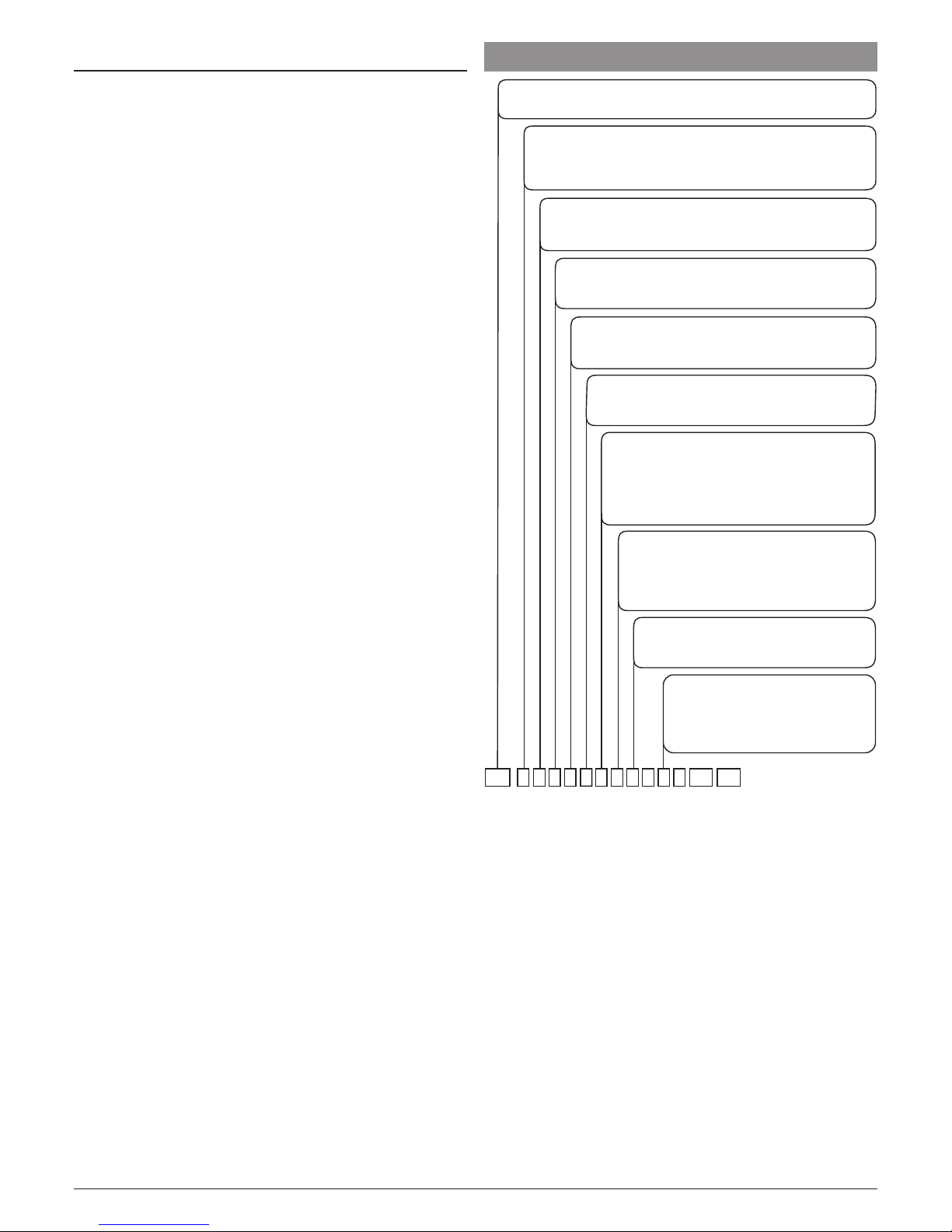
Ascon Tecnologic - e33 - OPERATING INSTRUCTIONS - PAG. 17
9.3 Functional features
Temperature Control: ON/OFF mode;
Defrost control: Interval cycles or evaporator temperature by
electric heating/stopping compressor or hot-gas/reverse cycle;
Measurement range:
NTC: -50 ÷ +109°C/-58 ÷ +228°F;
Display resolution: 1° or 0.1° (range -99.9 ÷ +99.9°);
Overall accuracy: ±(0.5% fs + 1 digit);
Sampling rate: 130 ms;
Display: 3 Digit Red or Blue (optional), height 17.7 mm;
Software class and structure: Class A;
Compliance: Directive 2004/108/CE (EN55022: class B;
EN61000-4-2: 8kV air, 4kV cont.; EN61000-4-3: 10V/m;
EN61000-4-4: 2kV supply and relay outputs, 1kV inputs;
EN61000-4-5: supply 2kV com. mode, 1 kV\diff. mode;
EN61000-4-6: 3V),
Directive 2006/95/CE (EN 60730-1, EN 60730-2-9),
Control 37/2005/CE (EN13485 air, S, A, 2, -50°C +90°C with
probe NTC 103AT11).
10. INSTRUMENT ORDERING CODE
MODEL
e33 - = Instrument with mechanical keyboard
a: POWER SUPPLY
D = 230 VAC
C = 115 VAC
F = 12 VAC/VDC
b: OUTPUT 1 (OUT 1)
H =
Out1 Relay
SPST-NO 16A-AC1 (f
or resistive loads
)
R =
Out1 Relay
SPST-NO 30A-AC1 (f
or resistive loads
)
d: OUTPUT 3 (OUT 3)
R =
Out3 Relay
SPST-NO 5A-AC1 (f
or resistive loads
)
- = No
c: OUTPUT 2 (OUT 2)
R =
Out2 Relay
SPDT 8A-AC1 (f
or resistive loads
)
- = No
i, k: RESERVED CODES; ll, mm: SPECIAL CODES
cae33 -b d
e: BUZZER
B = Buzzer
- = No
e
f: POWER SUPPLY AND OUTPUT TERMINALS
V = Screw terminals (standard)
E = Complete removable screw terminals
(step 5.00)
N = Removable screw terminals (step 5.00)
F = Faston 6.3 mm
g: INPUT
TERMINALS
V = Screw terminals (standard)
E =
Complete removable screw terminals
(step 5.00)
N =
Removable screw terminals (step 5.00)
h: DISPLAY
I = Red (standard)
C = Blue
fgh ll
mm
i j k
j: PACKAGING + BRACKET TYPE
B = At package + “Butterfly” type
brackets (standard)
C = At package + gasket + screw
type bracket

Ascon Tecnologic - e33 - OPERATING INSTRUCTIONS - PAG. 18

Ascon Tecnologic - e33 - OPERATING INSTRUCTIONS - PAG. 19

Ascon Tecnologic - e33 - OPERATING INSTRUCTIONS - PAG. 20
 Loading...