

ascobloc AEH 300, AEH 300.110, AEH 503.110, AEH 503, AEH 505 Operating Instructions Manual
...Page 1
1
EN
Operating Instructions
ASCOLINE 700
AEH 3xx, 5xx, 7xx
Electric Range with
Glass Ceramic Surface
Quality and expertise in
stainless steel
Page 2

Operating instructions Ascoline 700, AEH 3xx, 5xx, 7xx
1 Table of Contents
Page
1 Table of Contents ................................................................................................................. 1
2 General information on the appliance ................................................................................ 2
3 Details for the secure handling of the appliance .............................................................. 2
3.1 General Details ....................................................................................................................... 2
3.2 Safety instructions for handling, cleaning and repair ............................................................. 2
3.3 Shipping instructions .............................................................................................................. 3
3.4 Installation instructions ........................................................................................................... 3
4 Installation............................................................................................................................. 3
4.1 Setting up ............................................................................................................................... 3
4.2 Connections............................................................................................................................ 3
5 Proper Use of the Equipment .............................................................................................. 4
5.1 Bringing into use ..................................................................................................................... 4
5.2 Operating ................................................................................................................................ 4
5.3 Cleaning ................................................................................................................................. 5
6 Maintenance .......................................................................................................................... 5
6.1 Maintenance ........................................................................................................................... 5
6.2 Measures in case of a longer breakdown .............................................................................. 6
7 Faults and their Rectification .............................................................................................. 6
7.1 Fault rectification .................................................................................................................... 6
7.2 Customer Service ................................................................................................................... 6
8 Spare parts ............................................................................................................................ 7
8.1 Spar parts list for glass ceramic ranges ................................................................................. 7
8.2 Illustrations ............................................................................................................................. 8
9 Declaration of conformity .................................................................................................. 10
Enclosure
• Technical data sheet
• Wiring diagram
• Advice on cleaning and repair
Dear customer,
Please make sure that you have read this manual attentively before the initial operation of the appliance. It contains crucial
information on the initial operation, usage and maintenance of the appliance. Particularly pay attention to security advice in
the following text.
Provide easy access to this manual for any operating staff. In addition to this manual you will also find further information for
your staff.
Hazard symbol description
General danger sign
The nonobservance of security advice leads to danger or damage of the appliance
Hot surfaces. Contact may lead to injuries.
ascobloc Gastro-Gerätebau GmbH 01156 Dresden, Grüner Weg 29 Germany
Tel. +49 351 4533-0 Fax +49 351 4537-339 Email:
Subject to change without notice!
[email protected] AEHC3ff.doc Edition: 19.11.2018
1
Page 3
Operating instructions Ascoline 700, AEH 3xx, 5xx, 7xx
Type
Specification
Ident
-
No.
Free-standing appliances
Wall and table top appliances
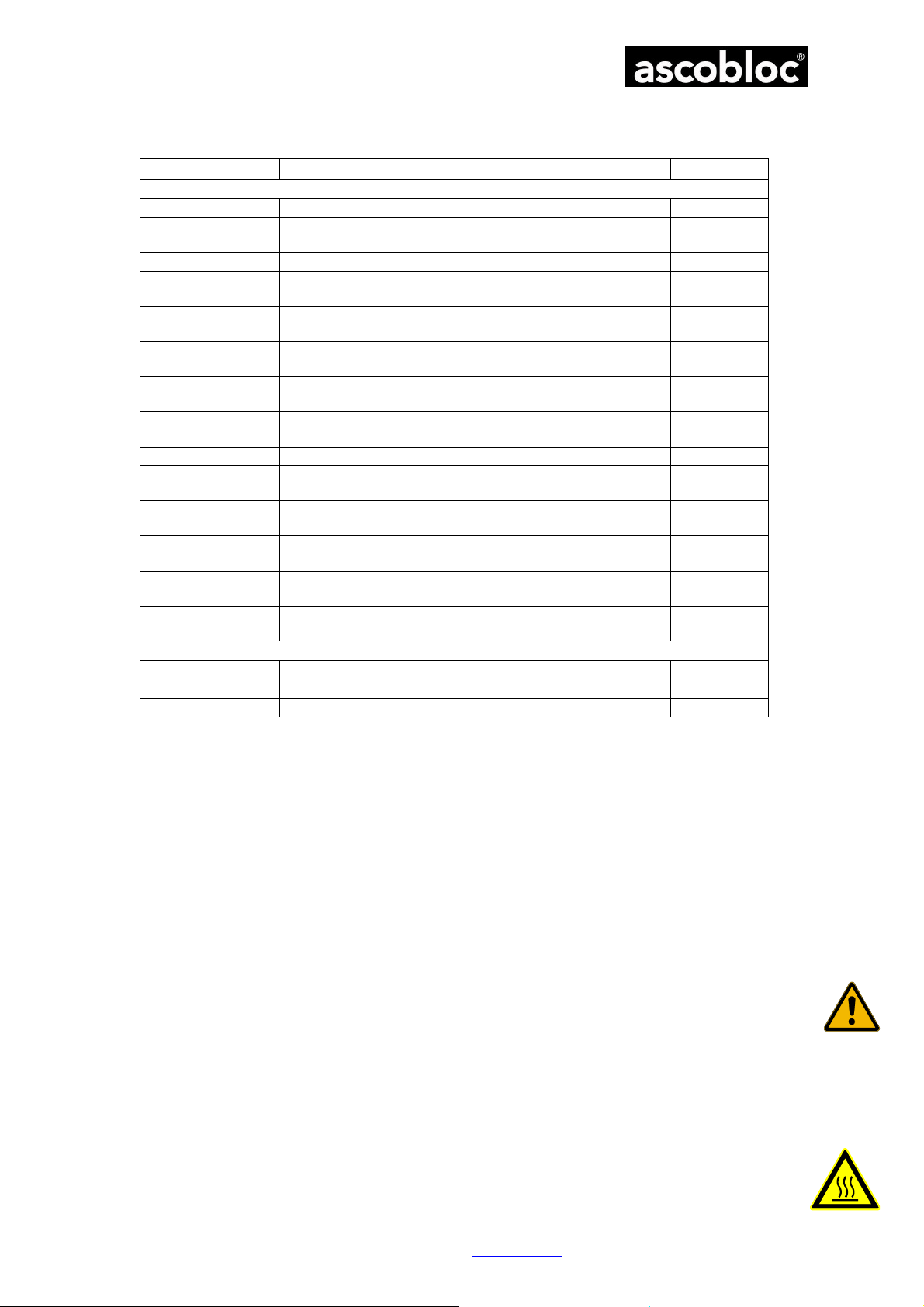
2 General information on the appliance
AEH 300 Electric Range with glass ceramic surface, 2 cooking zones 6510.100
AEH 300.110
AEH 500 Electric Range with glass ceramic surface, 4 cooking zones 6511.100
AEH 500.110
AEH 503
AEH 503.110
AEH 505
AEH 505.110
AEH 700 Electric Range with glass ceramic surface, 6 cooking zones 6514.100
AEH 700.110
AEH 703
AEH 703.110
AEH 705
AEH 705.110
Electric Range with glass ceramic surface, 2 cooking zones,
pot detection
Electric Range with glass ceramic surface, 4 cooking zones,
pot detection
Electric Range with glass ceramic surface, 4 cooking zones,
baking oven
Electric Range with glass ceramic surface, 4 cooking zones,
pot detection, baking oven
Electric Range with glass ceramic surface, 4 cooking zones,
air-vented baking oven
Electric Range with glass ceramic surface, 4 cooking zones,
pot detection, air-vented baking oven
Electric Range with glass ceramic surface, 6 cooking zones,
pot detection
Electric Range with glass ceramic surface, 6 cooking zones,
baking and roasting oven
Electric Range with glass ceramic surface, 6 cooking zones,
pot detection, baking oven
Electric Range with glass ceramic surface, 6 cooking zones,
air-vented baking oven
Electric Range with glass ceramic surface, 6 cooking zones,
pot detection, air-vented baking oven
6510.110
6511.110
6512.100
6512.110
6513.100
6513.110
6514.110
6515.100
6515.110
6516.100
6516.110
AEH 308 Electric Range with glass ceramic surface, 2 cooking zones 6610.100
AEH 508 Electric Range with glass ceramic surface, 4 cooking zones 6611.100
AEH 708 Electric Range with glass ceramic surface, 6 cooking zones 6614.100
(Technical data sheet enclosed)
3 Details for the secure handling of the appliance
3.1 General Details
These are technical appliances which are exclusively made for industrial use and operation under
supervision.
The electric ranges are only intended for commercial cooking.
The appliances are not intended to heat rooms or other materials, except those, which are normally used
for cooking.
The appliance should only be operated in a sufficiently ventilated room.
Technical modifications of the appliance without a prior written authorisation by the manufacturer are not
allowed and result in a total loss of warranty. The product liability of the manufacturer invalidates
immediately.
These instructions must be anounced to all employees concerned when they are trained in how to use
the appliance.
3.2 Safety instructions for handling, cleaning and repair
• Overheated fat and oil is inflammable by themselves. Meals with fat and oil should only be dressed
supervised.
• Some parts, like the oven door or the covering plate are, depending on the frying and roasting function,
very hot. Save yourself by only touching the appliance at the control elements and ware appropriate
clothing, which avoids the direct contact with your skin.
ascobloc Gastro-Gerätebau GmbH 01156 Dresden, Grüner Weg 29 Germany
Tel. +49 351 4533-0 Fax +49 351 4537-339 Email:
Subject to change without notice!
[email protected] AEHC3ff.doc Edition: 19.11.2018
2
Page 4

Operating instructions Ascoline 700, AEH 3xx, 5xx, 7xx
• Operation and cleaning must be carried out by trained employees. Maintenance and repair must be
carried out by qualified personnel only.
• The manufacturer is not responsible for damages caused by improper installation or operation. In these
cases of damage the warranty becomes void.
• When carrying out repair all poles of the appliance must be free of voltage (use cut-off device provided
by customer, e.g. fuse).
3.3 Shipping instructions
• We advise to ship ascobloc-appliances only in their original packing in order to avoid unnecessary
damage or costs.
• Check appliances for damage before unpacking and again before installation.
• Do not raise or move the appliance using the top plate, the lower edges on the side or the door
handles. Instead please use the lower edge at the front or at the back.
3.4 Installation instructions
The appliance is wired up to the connection box. To ensure the safety of our products it is necessary that
every connection process is carried out by an expert. Please allow these experts to look at these
documents. The statutory regulations (Germany VDE, Austria ÖVE, Switzerland SEV etc.) as well as the
connection conditions of the local electricity supply company must be observed completely.
Before beginning the installation work, it should be checked that the mains voltage, mains type and the
current rating of the fuse match the values given on the type plates. An isolating device in the customer's
scope of supply that is effective on all poles must be provided, e.g. contactor fuses with at least 3 mm
contact gaps, so that the equipment is disconnected from the power supply during repair and installation
work. Connection to an equipotential bonding system is available (check effectiveness).
Do not bend, squash or damage cables on any sharp edges. Lay the cables in such a way that they
cannot be brought into contact with hot parts. The connection cable leading through the appliance must
be fully sheathed from the connection point up to the entrance to the terminal box. The appliance is
intended for fixed connection; it is not permitted to connect the appliance using plugs.
4 Installation
4.1 Setting up
Do not install the appliance next to walls, kitchen furniture, decorations or other inflammable materials.
Nonobservance causes fire danger!!! For the minimum distance please refer to the wiring diagram and
product description. Pay attention to the local fire protection regulations!
The appliance must be levelled out by using a spirit level. Otherwise the drawers and doors will not work
and shut perfectly. Appliances with height-adjustable feet can level the uneven floor slightly (+/- 20 mm)
by turning the feet. In case of installation on a plinth the appliance may be levelled by an appropriate
underlay.
4.1.1 Free-standing appliance
For installation as a free-standing appliance, it must be attached in a suitable way to prevent the
appliance from tipping over or moving.
4.1.2 Installation in groups or blocks
For installation in groups or blocks the appliances must be connected with each other by using suitable
connection elements. This is in the interest of hygiene. Furthermore, take note of the respective
instructions in the appliances’ leaflet, brochure or installation diagram.
4.2 Connections
Refer to details about connections in the enclosed wiring diagram and in the description of the appliance.
Please check whether the dimensions and the position of the electric outlet correspond to the
specifications in the appliances’ leaflet, brochure or installation diagram.
The terminal box is located behind the front panel A. Please make the connections according to the valid
wiring diagram. The number of the applicable wiring diagram is on the appliance identification plate.
4.2.1 Free-standing appliance
Connections can be made underneath or at the back of the appliance. For connection underneath a gap
of at least 500 mm towards the footprint is needed.
4.2.2 Wall and table top appliance, connection to an installation wall or wall-mounted frame
When mounting the appliance next to an installation wall or a wall-mounted frame (ACC 881),
connections underneath or at the back of the appliance should be used.
ascobloc Gastro-Gerätebau GmbH 01156 Dresden, Grüner Weg 29 Germany
Tel. +49 351 4533-0 Fax +49 351 4537-339 Email:
Subject to change without notice!
[email protected] AEHC3ff.doc Edition: 19.11.2018
3
Page 5

Operating instructions Ascoline 700, AEH 3xx, 5xx, 7xx
4.2.3 Wall and table top appliance, connection through rear cover plate
There is an angle bracket with a hole on the right rear cover plate of the appliance covering the entrance
to the duct. Remove this angle bracket and turn it 180° before screwing it on again. The hole in the angle
bracket should now enable the entry to the duct through the rear wall of the appliance.
5 Proper Use of the Equipment
5.1 Bringing into use
Before initiation detach the protection film off the steel surface.
Clean the appliance with diluted soap solution.
5.2 Operating
5.2.1 Glass Ceramic Hobs
Use pots with flat and flush bottoms for a better temperature transmission.
The glass ceramic hobs have two separately adjustable cooking zones, one on the front and one on the
back.
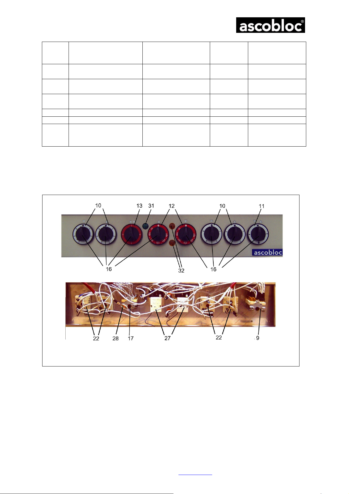
The knobs, used for the temperature control (Illustration 1, 10), and the signal lamp are placed on the
control panel.
By turning the knob you can switch on the cooking zone and bring it to the designated temperature.
The temperature is continuously adjustable from 80° to 380°C.
If the cooking zone is on, the signal lamp illuminates green.
If the appliance is shut down, please turn all knobs to “zero”.
5.2.2 Glass Ceramic Hobs with Pot detection (optional)
Turn the knob of the regarding cooking zone to the right. The green signal lamp has to illuminate all the
time. Afterwards put a suitable cooking or roasting pot on the regarding cooking zone and switch on the
pot detection. Due to the heating with the pot detection it is possible to save energy, because the heating
zone only switches on, when you put the pot on it. The pot detection only works, if the pot has a size of
the used cooking zone. In case of using smaller pots it could be possible, that you need to switch of the
pot detection, because the pot needs to have a minimum size.
Remark: When initiating or in case of voltage drop, first switch on the cooking zone, then draft the pot to
enable the pot detection.
Switch (Illustration 1, 11)
Position 0 pot detection on
Position 1 pot detection off
5.2.3 Baking Room (optional)
Baking and Roasting Oven:
When using a baking room with additional air-vented heating the switch (Illustration 1;13) needs to be in
position mode (II)
By turning the knobs (temperature control) you can switch on the temperature, separately for upper
(12▲) and lower heat (12▼)
If the baking room is on, either the green or the yellow signal lamp illuminates
By reaching of the designated temperature the yellow signal lamp extinct
Air-vented Baking Oven:
Turn the switch (13) to air-circulation (I)
By turning the knob (12▲) to upper heat, the temperature is switched on,
If the baking room is on, either the green or the yellow lamp extinct
The temperature during the air-circulation can be 250°C at most.
Always preheat the oven, when baking and roasting, to achieve the best result possible.
Attention: The heating and the ventilator remain on, despite an opened oven door!
Turn the heating capacity back to step I if the cooking zone is empty, to avoid unnecessarily high
temperatures of the appliance and ambiance temperature, as well as unnecessarily high energy
consumption. High temperatures during idling can cause a shortened durability of the thermal loaded
components.
ascobloc Gastro-Gerätebau GmbH 01156 Dresden, Grüner Weg 29 Germany
Tel. +49 351 4533-0 Fax +49 351 4537-339 Email:
Subject to change without notice!
[email protected] AEHC3ff.doc Edition: 19.11.2018
4
Page 6

Operating instructions Ascoline 700, AEH 3xx, 5xx, 7xx
5.3 Cleaning
Please pay attention to the hygienic regulations which are valid in your kitchen! These present
instructions are not substitutes for them.
Attention! Do not spray the appliances with water, steam jet or high-pressure cleaners. The appliance
has to be turned off when cleaning the surrounding with water, steam jet or high-pressure cleaner.
Before cleaning the appliance it must be switched off and allowed to sufficiently cool down. Parts of the
appliance or accessories that come in contact with food must be thoroughly rinsed with drinking water
after being treated with cleaning material. Do not use inflammable liquids for cleaning.
To avoid trouble during operation and for reasons of hygiene, the appliance should be cleaned every day
after being used.
Glass Ceramic
The glass ceramic surface is easier to clean than common cooking plates, but even they need a regular
caring.
To detach gross dirt always use the glass ceramic scraper (ACC 560). If using improper scrapers the
surrounding silicone gasket could be damaged.
Over boiled and entombed materials have to be picked up immediately, to avoid encrustations.
Avoid contact between the hot cooking zone and any melting materials, e.g. plastics, film, and especially
sugar-containing meals. Lift any kind of encrustations immediately from the cooking zone with the glass
ceramic scraper to avoid partial damage.
Clean the cooking zone multiple times a day, but at least after operation end. In case of slight dirt it
suffices to clean the cooking zone with a wet drapery and a little bit of rinsing agent. In case of heavy dirt
first pick up gross dirt with the glass ceramic scraper. Afterwards clean it up with fine scrubbing milk,
coarse scrubbing brush or emulsified steel wadding (e.g. AKO-PADS, Abbrazzo).
The use of plastic sponges with embedded sand or steel wool shall be avoided in any case. Sand
dropped off on the glass-ceramic surface during salad washing or potato peeling may provoke scratches
when pots are slides. Wash off with clear water!
Should a grey film coat (layer of calcium) arise, please wipe off with diluted vinegar.
We recommend the following devices:
ACC 558 Softening agent
ACC 559 Substitute plates for glass ceramic scraper
ACC 560 Glass ceramic scraper
ACC 561 Maintenance agent for glass ceramic hobs on ranges
Cover plate
In case of persevering dirt, the cover plate can be sprayed with customary cleaning agents for
stainless steel.1 After an exposure time of 10-20 minutes, clean the cover plate with a rough sponge
and water. Do not flood the cover plate, just wipe it out with a couple of draperies.
Baking oven
The lateral supporters for the basins can be unscrewed, removed and cleaned (in a dishwasher). The
bottom of the baking oven can also be removed.
Spray the supporting grids and the refining room with customary cleaning agents or baking oven
cleaner. After an exposure time of 10-20 minutes, clean the baking room with a rough sponge and
water and open the baking oven door, to ventilate the baking oven.
1
Attention! The cleaning agents used, have to be free of chlorous and fluoric compounds as these
halogenides can even corrode high-quality stainless steel.
6 Maintenance
6.1 Maintenance
Please notice the cleaning and maintenance instructions enclosed!
AEH 503/503.110/505/505.110/703/703.110/705/705.110
Please check the function of the ventilator on a regular base, at least one time a week.
The ventilator of the appliance works blameless, when air comes out of the ventilation slot underneath the
panel (bottom).
Please check the function of the ventilator on a regular base, at least one time a week.
When air comes out of the ventilation slot underneath the panel (bottom) the ventilator of the appliance
works blameless.
ascobloc Gastro-Gerätebau GmbH 01156 Dresden, Grüner Weg 29 Germany
Tel. +49 351 4533-0 Fax +49 351 4537-339 Email:
Subject to change without notice!
[email protected] AEHC3ff.doc Edition: 19.11.2018
5
Page 7
Operating instructions Ascoline 700, AEH 3xx, 5xx, 7xx
6.2 Measures in case of a longer breakdown
Please clean the appliance efficiently. The baking oven has to be dried completely, before closing the
door.
If necessary, cut he appliance off the electricity network.
7 Faults and their Rectification
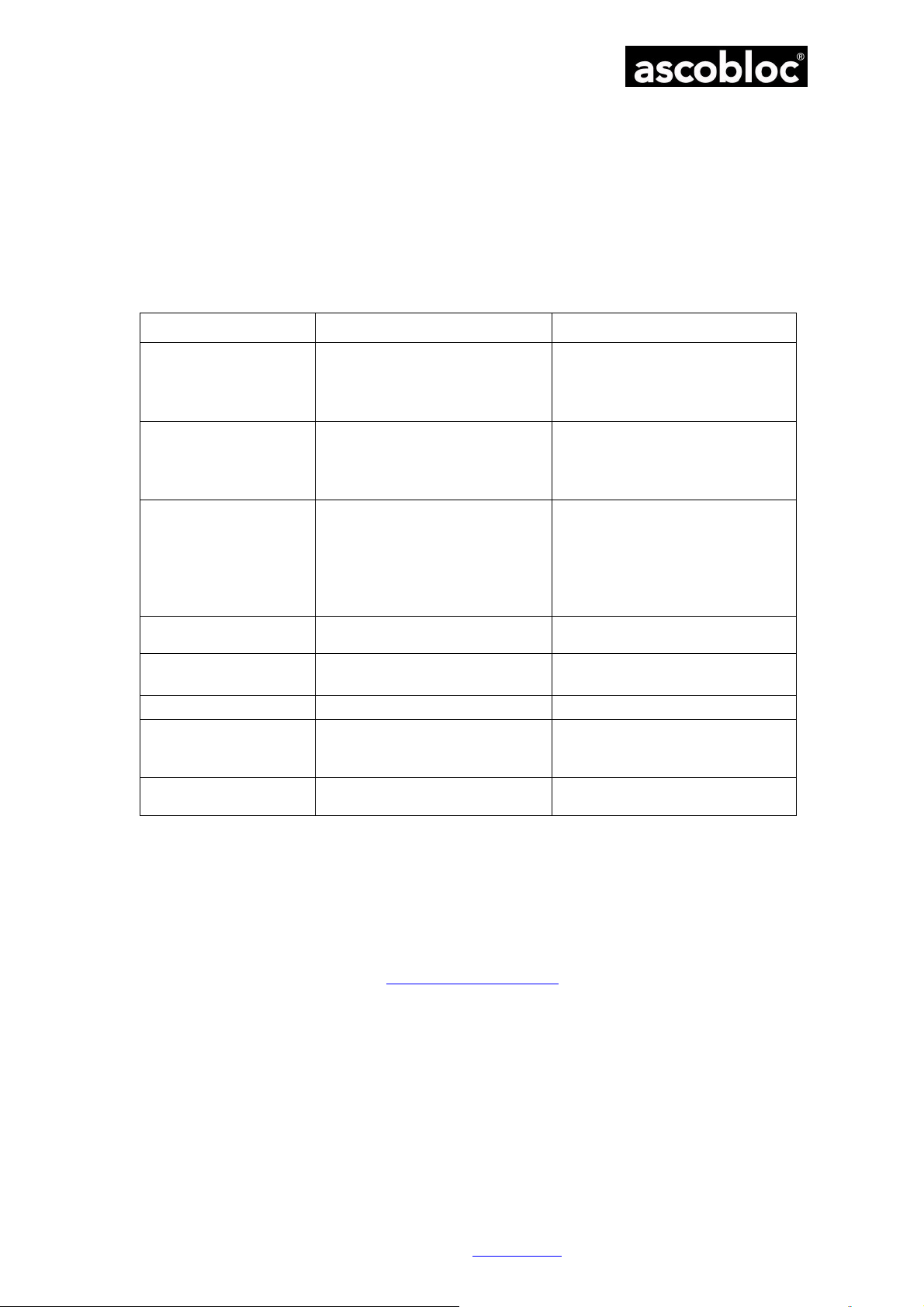
7.1 Fault rectification
Do always remove the plug before repair!
Failure Possible Cause Solution
The green signal lamp
illuminates, nevertheless
there is no heat emission.
Pot detection does not
work
No heat emission in the
baking oven
Fuse disconnects
repeatedly
Baking room door does
not close
Baking room leaky worn gaskets replace
Green lamp does not
illuminate after switching
on the appliance
Heating element upper
heat is not fixed
Repair should only be carried out by qualified staff. Please state the serial number and the type
designation which you will din on the appliance identification plate.
Cooking zone, heating element,
switch or temperature control is
broken,
Phase is missing
Switch to position 0
Pot to small
Radiant heating element / conductor
plate is broken
Network connection is broken
Fuse by customer disconnected
Green signal lamp illuminates,
nevertheless there is not heat
emission
> heating element is broken
Wrong fuse protection or short-
circuit
Not enough tension
Network connection or fuse is
broken
Signal lamp is broken
Bracket for heating rod is not
attached correctly
Replace broken component
Turn the switch to position 1
Use a bigger pot
Replace
refit
refit
replace heating element
replace broken component
adjust
replace fuse
fix again
7.2 Customer Service
ascobloc Gastro-Gerätebau GmbH 01156 Dresden, Grüner Weg 29 Germany
Tel. +49 351 4533-0 Fax +49 351 4537-339 Email:
Subject to change without notice!
[email protected] AEHC3ff.doc Edition: 19.11.2018
6
Page 8
Operating instructions Ascoline 700, AEH 3xx, 5xx, 7xx
1.
2.
3.
4.
5.
6.
7.
8.
9.
10.
11.
12.
13.
14.
15.
16.
17.
18.
19.
20.
21.
21.1
22.
ceramic cooking zones (with
23.
24.
25.
26.
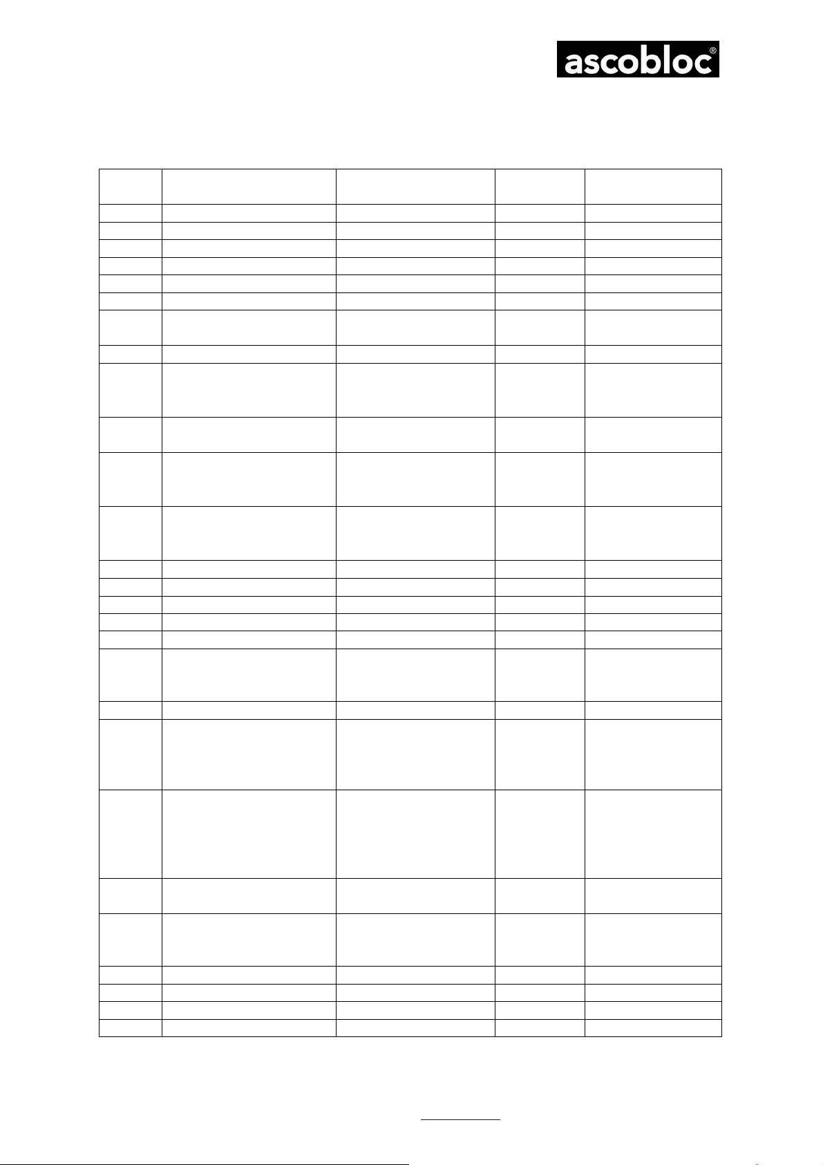
8 Spare parts
8.1 Spar parts list for glass ceramic ranges
Pos. Description Type / Specification Ident-No. Comment
Baking tray
Grid
Bottom
Register
Upper gasket (oven)
Gasket sideways (oven)
Foot
Knurled knob
Ein-, Ausschalter
Topferkennung
(Gerät mit Topferkennung)
Graduated collar
Temperature controler
Graduated collar for switch
of pot detection
(with pot detection)
Graduated collar
(upper & lower heating, aircirculation temperature)
Graduated collar (switch)
Hinge A
Hinge B
Knob
Switch
Glass ceramic hob
Scraper
Heating element for glass
ceramic cooking zone
radiant heating element 3,0
kW
AEH 503/505/703/705 08/2527
AEH 503/505/703/705 08/2459
AEH 503/505/703/705 06/3732
AEH 503/505/703/705 08/6280
AEH 503/505/703/705 04/1783
AEH 503/505/703/705 04/8356
not for
AEH 308/508/708
AEH 308/508/708 08/1320
AEH xxx.110 09/3022
08/2940
AEH xxx.110
AEH 503/505/703/705 08/2909
AEH 505/705 08/2916
AEH 703/705 04/5252
AEH 703/705 04/5253
09/2662
AEH 505/705 09/2197 X
AEH 30x
AEH 50x
AEH 70x
08/2470
AEH xxx 09/3580 X
08/6232
PD
08/6276
08/7424
08/7425
08/7426
PD
X
x
ascobloc Gastro-Gerätebau GmbH 01156 Dresden, Grüner Weg 29 Germany
Tel. +49 351 4533-0 Fax +49 351 4537-339 Email:
Heating element for glass
ceramic cooking zone
radiant heating element 3,0
kW, pot detection
(with pot detection)
Sensorelectronic pot
detection
Temperature control glass
pot detection
Cross-flow ventilator
Ventilator R2K
Heating element 6000 W AEH 505/705
Heating element 2100 W
AEH xxx.110 09/3579
AEH xxx.110 09/2997
AEH xxx.110 09/2995
AEH 505/705 09/1047 X
AEH 505/705 09/1503 X
AEH 503/505/703/705 09/2341 X
Subject to change without notice!
PD
Radiant heating
element
X
Sensorelectronic
PD
x
09/1945 X
[email protected] AEHC3ff.doc Edition: 19.11.2018
7
Page 9
Operating instructions Ascoline 700, AEH 3xx, 5xx, 7xx
27.
28.
29.
30.
31.
32.
33.
Temperature control
(upper & lower heating, aircirculation temperature)
Temperature control
Cross-flow ventilator
Temperature control
Glass ceramic hob
Air-circulation temperature
control
Signal lamp green
Signal lamp yellow
Temperature control glass
ceramic cooking zone
AEH 503/505/703/705 09/2085 X
AEH 505/705
AEH 505/705
09/2092 X
09/2093 X
AEH xxx
09/1933 X
09/3578 X
09/1687 X
09/2995
09/3459
09/3460
PD = Spare parts only for appliances with pot detection AEH 30x.110 / AEH 50x.110 / AEH 70x.110
x = Replacement or repair only by authorised specialists.
8.2 Illustrations
X
Illustration 1 Switch panel (pictured AEH 505.110) and installation room behind the switch
panel
ascobloc Gastro-Gerätebau GmbH 01156 Dresden, Grüner Weg 29 Germany
Tel. +49 351 4533-0 Fax +49 351 4537-339 Email:
Subject to change without notice!
[email protected] AEHC3ff.doc Edition: 19.11.2018
8
Page 10
Operating instructions Ascoline 700, AEH 3xx, 5xx, 7xx
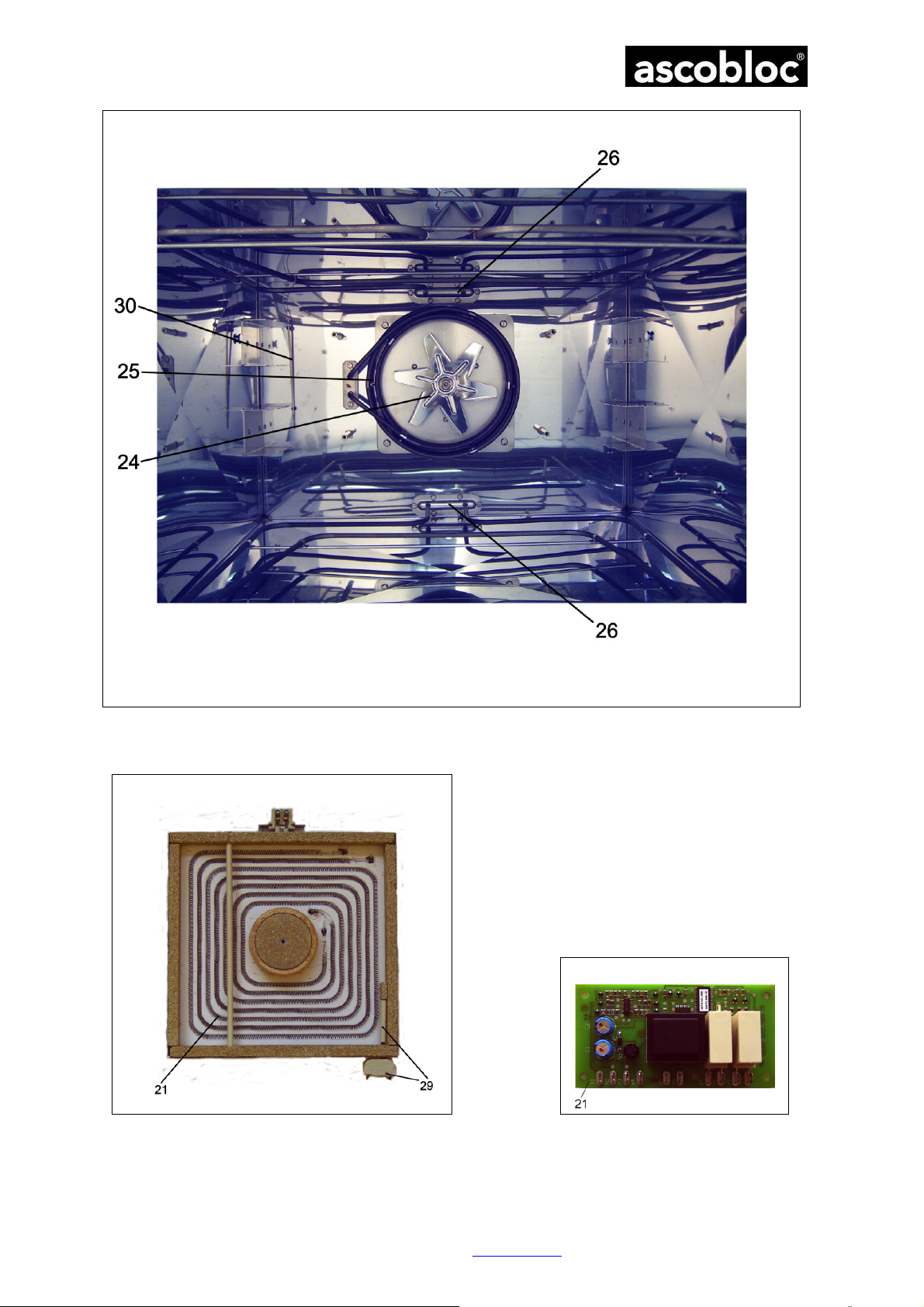
Illustration 2 Baking oven (without bottom, register, partition plate, air-circulation heating element)
Illustration 3 Radiant heating element (pictured AEH xxx.110 with pot detection and conductor
plate)
ascobloc Gastro-Gerätebau GmbH 01156 Dresden, Grüner Weg 29 Germany
Tel. +49 351 4533-0 Fax +49 351 4537-339 Email:
Subject to change without notice!
[email protected] AEHC3ff.doc Edition: 19.11.2018
9
Page 11
Operating instructions Ascoline 700, AEH 3xx, 5xx, 7xx
Type
Specification
Ident
-No.
Free-standing appliances
Wall and
table top appliances
9 Declaration of conformity
EC-Declaration of conformity for CE-mark
The manufacturer
Gastro-Gerätebau GmbH
Grüner Weg 29
D-01156 Dresden, Germany
declares herewith that the appliances described below
AEH 300 Electric Range with glass ceramic surface, 2 cooking zones 6510.100
AEH 300.110
AEH 500 Electric Range with glass ceramic surface, 4 cooking zones 6511.100
AEH 500.110
AEH 503
AEH 503.110
AEH 505
AEH 505.110
AEH 700 Electric Range with glass ceramic surface, 6 cooking zones 6514.100
AEH 700.110
AEH 703
AEH 703.110
AEH 705
AEH 705.110
Electric Range with glass ceramic surface, 2 cooking zones,
pot detection
Electric Range with glass ceramic surface, 4 cooking zones,
pot detection
Electric Range with glass ceramic surface, 4 cooking zones,
baking oven
Electric Range with glass ceramic surface, 4 cooking zones,
pot detection, baking oven
Electric Range with glass ceramic surface, 4 cooking zones,
air-vented baking oven
Electric Range with glass ceramic surface, 4 cooking zones,
pot detection, air-vented baking oven
Electric Range with glass ceramic surface, 6 cooking zones,
pot detection
Electric Range with glass ceramic surface, 6 cooking zones,
baking and roasting oven
Electric Range with glass ceramic surface, 6 cooking zones,
pot detection, baking oven
Electric Range with glass ceramic surface, 6 cooking zones,
air-vented baking oven
Electric Range with glass ceramic surface, 6 cooking zones,
pot detection, air-vented baking oven
6510.110
6511.110
6512.100
6512.110
6513.100
6513.110
6514.110
6515.100
6515.110
6516.100
6516.110
ascobloc Gastro-Gerätebau GmbH 01156 Dresden, Grüner Weg 29 Germany
Tel. +49 351 4533-0 Fax +49 351 4537-339 Email:
AEH 308 Electric Range with glass ceramic surface, 2 cooking zones 6610.100
AEH 508 Electric Range with glass ceramic surface, 4 cooking zones 6611.100
AEH 708 Electric Range with glass ceramic surface, 6 cooking zones 6614.100
satisfy the provisions of
the EMC Directive 2004/108/EC,
of the Low Voltage Directive 2006/95/EC, including modifications valid at the time of the declaration.
The following harmonised standards were applied:
DIN EN 60335-2-6:2005-09 Safety of electric appliances for domestic use or similar purpose –
Part 2-6: Special requirements for fixed ranges, hobs, baking ovens and
similar appliances
DIN EN 60335-2-36:2005-09 Safety of electric appliances for domestic use or similar purpose –
Part 2-36: Special requirement for electric ranges, baking and roasting oven
and cooking plate for industrial use
DIN EN 60335-1:2007-02 Safety of electric appliances for domestic and similar purpose – Part 1:
General demands
DIN EN 55014-1: 2010-02 Electromagnetic compatibility - Requirements for household appliances,
electric tools and similar apparatus - Part 1: Emission
Subject to change without notice!
[email protected] AEHC3ff.doc Edition: 19.11.2018
10
Page 12

Operating instructions Ascoline 700, AEH 3xx, 5xx, 7xx
DIN EN 55014-2:2009-06 Electromagnetic compatibility - Requirements for household appliances,
electric tools and similar apparatus - Part 2: Immunity
The following national or international standards (or parts/clauses) and specifications have been applied:
DIN 18851:2003-06 Appliances for industrial kitchens – Ranges – Demands and Inspection
Dresden, 22.04.2010
ppa. R. Ziegler
Technical director
ascobloc Gastro-Gerätebau GmbH 01156 Dresden, Grüner Weg 29 Germany
Tel. +49 351 4533-0 Fax +49 351 4537-339 Email:
Subject to change without notice!
[email protected] AEHC3ff.doc Edition: 19.11.2018
11
 Loading...