

Page 1
Service manual
Type: WM50
Replaces
New type old type Main differences Product info
WM33A WM33 Programmer no longer fitted, replaced by rotary switch
and electronic control card. E2 no longer fitted,
new programs. A
New panel graphic.
WM44A WM44 Programmer no longer fitted, replaced by rotary A
switch and electronic control card.
E2 no longer fitted, new programs.
New panel graphic.
WM50 NEW Electronic control with knob and 7-segment B
LED display. 11 programs.
WM55A WM55 New control card. New menu logic. C
New programs. Among other things, 1-24 hour delayed start.
New panel graphic. Shop program indicated on the display.
WM56 NEW Electronic control with buttons and display. D
8 programs. Shop program indicated on display.
WM66A WM66 See WM55A. C
Overview of new/modified types of
washing machines introduced to the
market in 2001
Product:
Date: 11.1.2002
Reference: N-Å Carlsson
Group: 21
Page: 1(10)
ASKO Cylinda’s range of washing machines was modified during the autumn of 2001. A brief
overview of the modifications which were carried out follows below.
Further information is given in the product data given below.
Front-loading
washing machine
Page 2
Service manual
Type: WM50
New type of washing machine
WM50
Product:
Date: 11.1.2002
Reference: N-Å Carlsson
Group: 21
B
Page:2(10)
This service manual is intended as a supplement to the W600 series Service Manual.
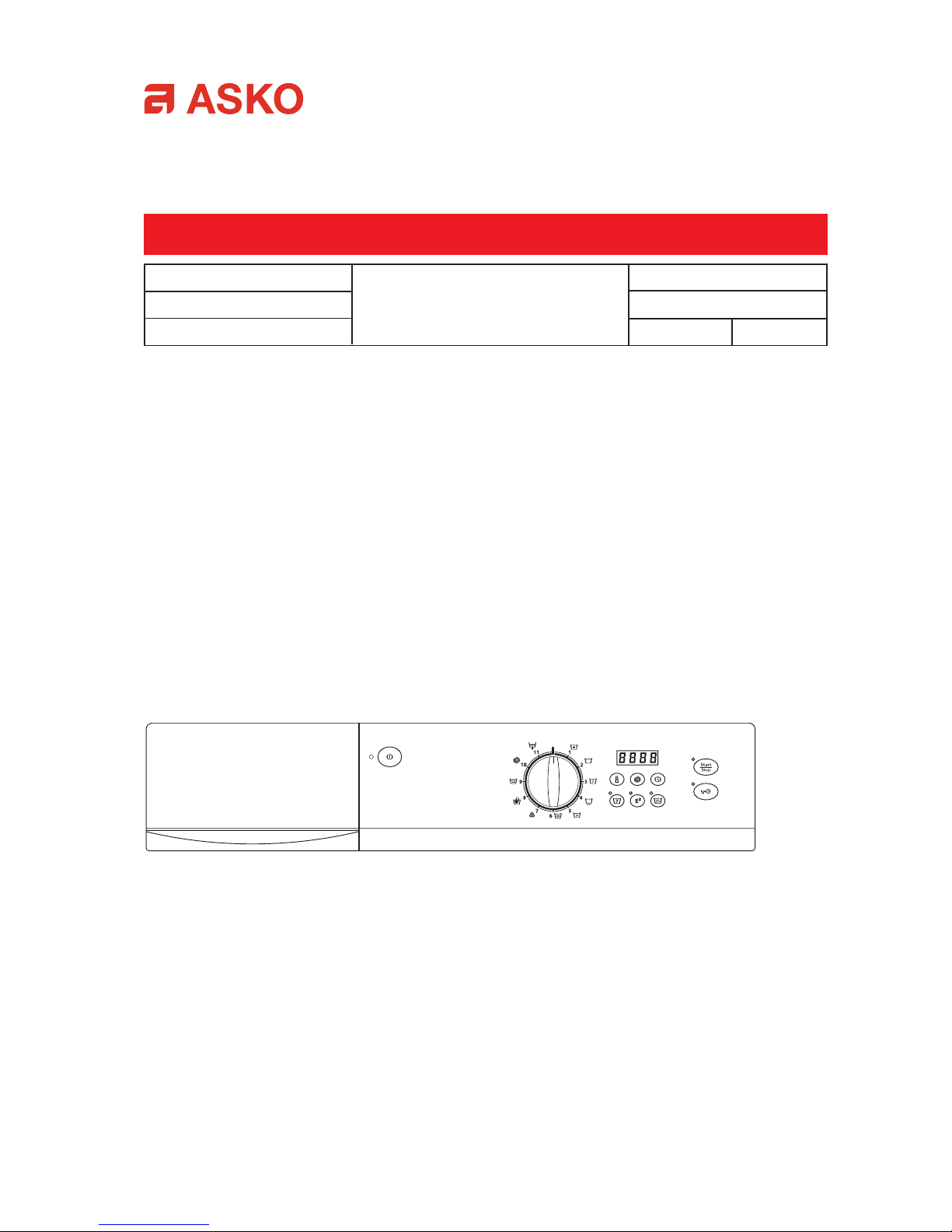
Example of WM50 Panel
General
Mechanically the machine is based on the WM55 (W640/W650), with the exception of the panel and
control unit. For more information see the service manual for the W600-series.
The machine is available with different pushbutton options, thus the pushbuttons may vary from one
market to another. See also loops on the control card below.
Contents
• Example of panel •
• General
• Handling
• Display indications
• Options and settings
• Error messages
• Faultfinding
• Consumption values
• Test program
• Loops on control card
• Settings
• Programs
• Component and measured values
Front-loading
washing machine
Page 3
Handling
1. Sort the wash
2. Press the main switch,
, open the door, , and place the wash in the machine.
3. Pour in the washing powder and also the rinsing aid if necessary.
4. Select program, adjust temperature, spin speed and option if necessary.
Settings appear on the display . Options appear as a lit LED alongside each button.
5. Close the door and start the program with the
- button.
T o interrupt a program hold down the
- button for 3 seconds.
6. At the end of the wash program open the door with
.
7. After the wash turn off the main switch
and close the wash door.
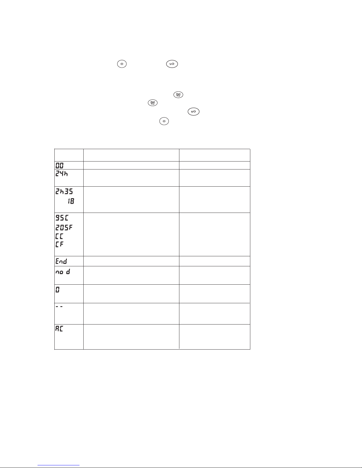
Display indications
The display shows Explanation
No program selected
One or two digits, followed by an h.
Delayed start has been selected and the program has started. The display shows the number of hours left until the
program starts.
One digit, an H followed by two digits or only 1-2
digits, means that a program is running.
The display shows the remaining time in the program
in hours and minutes.
Appears when temperature is selected. The temperature can be indicated either in degrees Celsius ( C)
or Fahrenheit (F).
CC and CF respectively mean that the machine is set
to the temperature of the incoming water.
To change the display see the section Washing temperature – Celsius or Fahrenheit in the instructions for
use.
Program ready. Remove the wash.
Can be displayed when selecting spin speed. Indicates No spin/No drain. The programme will then
be run without spins and will be completed with the
final rinse water still in the machine.
Can be displayed when selecting spin speed. Indicates No spin. The programme will then be run without spins.
When the Anti-crease option has been activated the
drum rotates a few times/min. for 2 hours after the
program has ended. In the mean time AC appears on
the display. You can end and open the door at ay time
by pressing the door opening button.
May appear instead of temperature when the setting
is not appropriate. For example temperature cannot
be selected for Rinse program.
Page 4
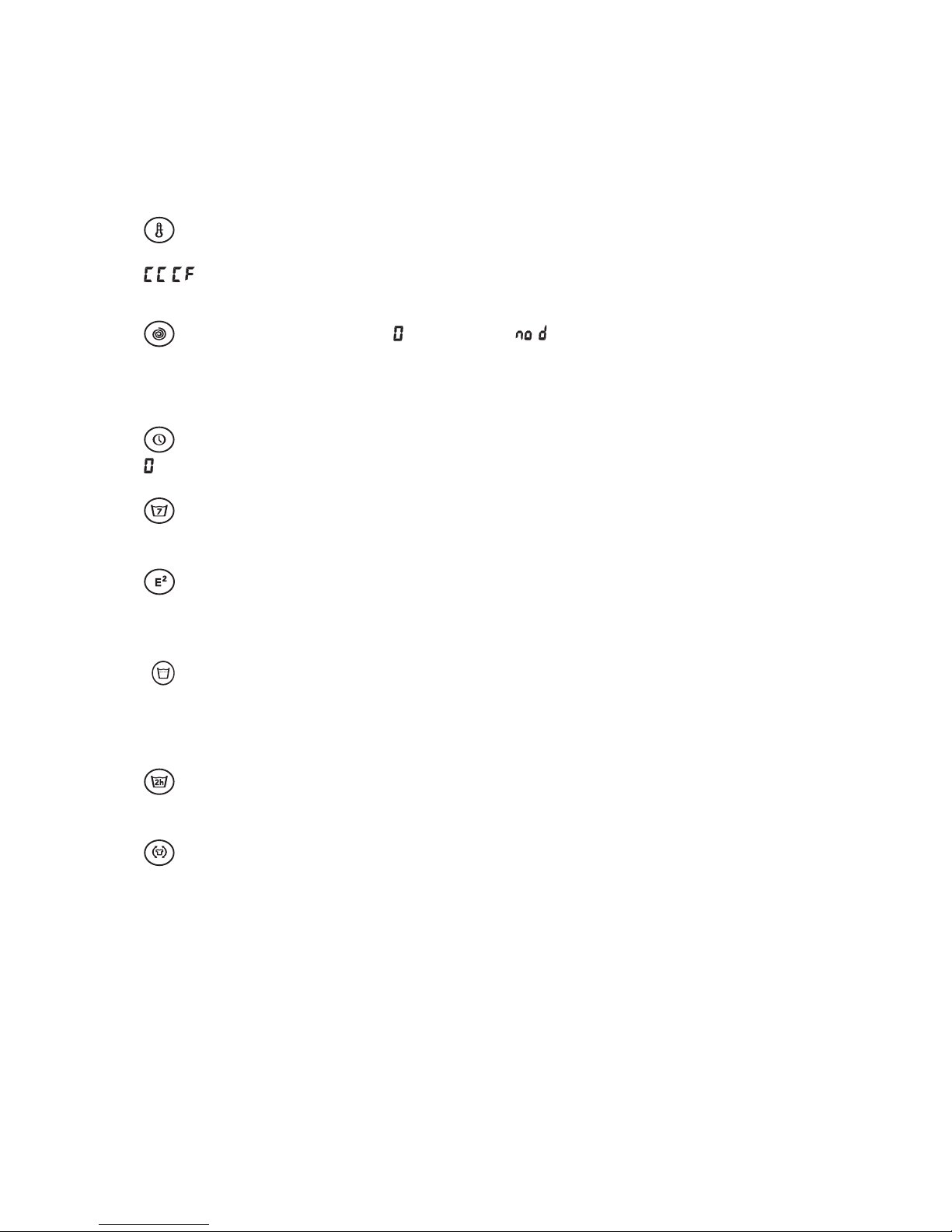
Options and settings (not all options are provided on all machines):
Settings are shown on the display or on LED’s alongside the respective buttons. The machine remembers
the settings and options you make for each program and start from them (with one or two exceptions –
temperatures over 60°C and delayed start) next time you select the program concerned.
Temperature 30-95°C or C
For certain programs it is not possible to select a temperature higher than 40°C, (see program table).
( when setting for Fahrenheit) means that the washing temperature will be equal to the temperature
of the incoming water.
Spin 400-1600 rpm. No spin ( ) or No drain ( ).
For certain programs it is not possible to select a speed higher than 800 rpm, see the table.
Speed 400-800 rpm means short spin.
Speed 1000-1600 rpm always means long final spin.
Delayed start (1-24 hours)
means that the option has been switched off and the program will start immediately as usual.
Super rinse
Super rinse means that extra rinses are added to the program (see program table).
E2 Economy and efficiency
The option means that the main wash is extended by 22 minutes. E2 can only be used on Heavy wash,
Normal wash and Light wash.
High water level
High water level means that an extra amount of water is used in the main wash and rinses. This option
may be used for all wash programs except Wool wash and Hand wash. These programs always have
high water level.
Pre-soak
Pre-soak means that the wash is left to soak two hours before the program starts.
Anti-crease
Anti-crease means that the machine rotates the drum one or two seconds per minute for two hours after
the end of the program. Anti-crease does not operate together with No spin and No spin/No drain.
Page 5

Flashing
Error messages
If an error or fault occurs in the course of the program this is indicated on the display .
N.B.
To reset the error message the main switch
must be turned off.
Faultfinding
The machine does not start
1. Is the washing door properly closed?
2. Check that the Delayed start option has been switched on. The time remaining until start will then
appear in whole hours on the display , e.g.
. To change: stop the program, change the setting and
restart.
3. Is there a break in the power supply? Check the house fuses (plugs).
4. Has the child lock been switched on? If so hold down the
- button for three seconds.
The display shows Description Explanation/proposed measure
Draining fault
The machine indicates that it has not succeeded in
pumping out the water within 3 minutes.
Where there is a draining fault check:
- that no object has caught in the drain hose outlet
- that the drain pump is not blocked by foreign objects. Clean the pump, see Chapter 11, Maintenance
and cleaning, in the instructions for use.
- that there are no kinks in the drain hose.
After the fault has been remedied run the Drain program. If this does not help, call service.
Water inlet fault
The indicates that it does not reach the water level
within 5 minutes.
Where there is a fault in the water supply, check:
- that the cock on the water pipe is open.
- that the screen in the machine water intake is not
blocked.
1. Close the water cock.
2. Unscrew the hose.
3. Clean the screen in the inlet valve on the machine.
4. Retighten the hose.
5. Open the water cock.
6. Run the program again to check whether the fault
has been remedied.
Thermistor fault
Temperature stop fault
Foaming (this function is not provided on all machines).
The fault indication appears at the end of the program, but foaming is checked after the main wash.
Run the rinse program once. Check the washing powder doe. Use low lather washing powder.
Door opening fault
The machine has not spun.
1. The machine has a built-in imbalance sensor which
causes the speed to be reduced or the spin to be jumped if there is major imbalance in the load. Turn off
the main switch and turn it on again. Open the door
and redistribute the wash.
2. After the fault is remedied run the Spin program.
You have tried to start a program with the door open.
Close the door and try again.
Flashing
Over flow
The sensor receives the first signal that Over flow has
taken place if, or example, an inlet valve has jammed or
if the machine has taken in water for a reason which the
sensor cannot control.
Machines with a float also receive the indication when
there is water at the bottom of the machine.
Wash motor fault
Interruption in any cables to the motor gives rise to this
fault, which means that an interruption in the power to the
motor may also produce the fault. Locking of the motor
also results in an error indication.
The machine indicates whether there is an interruption or short-circuit in the thermistor.
Indicates whether the temperature is not reached
within 80 mins., 30 mins. For wool and hand wash.
A fault has occurred on the control card, which must
be replaced to ensure complete safety.
Page 6

The following conditions apply to the consumption values indicated below:
T emperature of the incoming water: 15°C. Element power: 2000W. Options: none.
Consumption values
PROGRAMME MATERIAL/WASHING LOAD WATER CONSUMP- POWER CONSUMP- PROGRAMME TIME
TEMPERATURE(1) (2) TION (approx. litre) TION (approx. kWh) (approx. minutes)
Heavy wash Cotton, linen, 60°C 5,0 kg 5-rinse: 62 1,20 140
3-rinse: 52 135
Normal wash Cotton, linen, 60°C 5,0 kg 59 0,95 125
49 120
Light wash Cotton, linen, 60°C 5,0 kg 59 0,90 85
49 80
Synthetic wash Polyester, cotton / 3,0 kg 28 0,35 65
polyester, nylon, 40 C
Quick wash Cotton, linen, 60°C 5,0 kg 35 0,90 5 8
Super quick Polyester , cotton / 3,0 kg 22 0,30 3 5
wash polyester, nylon, 40 C
Wool wash Wool/Hand wash, IWS, 2,0 kg 54 0,30 40
Superwash, 30
°C
Hand wash W ool/Hand wash, IWS 2,0 kg 54 0,30 40
Superwash, 30°C
Rinse Cotton, linen 5,0 kg 7-12 0,05
programme
Spin Cotton, linen 5,0 kg ---- 0,05
Drain Cotton, linen 5,0 kg ---- ---- 1
(1) All programmes are set to the highest available spin speed.
(2) The machine can handle a maximum load of 6.0 kg.
Varies according
to model
Varies according
to model
Page 7

Test program
The machine control unit incorporates a built-in test program which can be used for faultfinding.
The machine can be provided with various silicon chips for different markets, which is why we have
numbered the buttons as shown in the figure below:
S1
S2
S4
S5
S3
S6
Hold down
Start
Stop
and at the same time press S5 5 times in 15 seconds to start level 1 of the test program
(see below).
Press S6 once to reach level 2.
Press S6 again to return to level 1.
Start
Stop
ends the test program.
Select level 1
S1 Inlet valve 1 (pre-wash compartment)
S2 Inlet valve 2 (main wash compartment)
S3 Inlet valve 3 (hot water)
S4 Inlet valve 4 (washing powder compartment)
S5 Door pull magnet
Select level 2
S1 Heating relay (clicking sound from relay on control unit).
S2 Drain pump
S3 Motor, normal running
S4 Motor, economy running
S5 Long spin
Page 8

Loops and their function.
J1 J2 J3 J4 J5
E 14
Loop Option Not broken / Closed Broken / Open
J1 Eco/High water level (S5) Eco High water level
J2 Pre-soak/Anti-crease (S6) Pre-soak Anti-crease
J3 Number of rinses 3 rinses 5 rinses
J4 Foaming Off On
J5 Not used
Reprogramming display and button functions.
Change from Celsius to Fahrenheit.
Program knob in 0 position 5 x Start + 5 x Temperature.
Change setting with Temperature button.
Setting child-safe Start.
Program knob in 0 position 5 x Start + 5 x Spin.
Change setting with the Spin button, 0 or 3 seconds.
Setting of water intake.
Program knob in 0 position 5 x Start + 5 x Later start.
Change setting with Later start button. C=cold E=mix H=hot
Setting of spin speed.
Program knob in 0 position. Hold down the Start button+ press 5 x Super rinse.
Release the Start button and change setting with Super rinse.
1300, 1400, 1500 or 1600 rpm.
Loops on WM 50 control card
Control unit Art.no. 8064257
Page 9

Program WM50 5 -rinse
Program WM50 3 -rinse
WM505566-5
Programme information Programme content
Programme No.
1/3 (2,0 kg)
1/2 (3,0 kg)
Rinse
Long spin
Programme
Max. quantity
Temperature
°C (A)
Max. spin speed
rev/min
Pre-wash
Main wash
Spin
Rinse (B)
Spin
Rinse (B)
Spin
Other
1/1 (6,0 kg)
Wash Short spin
(max. 800 rev/min)
(A) C in the display denotes the temperature of
the incoming water.
(B) The Super rinse On option provides two
extra rinses before the final normal rinse.
(C) Delicate wash – high water level.
C,30-95 1500Heavy wash1
C,30-95 1500Normal wash2
C,30-95 1500Light wash
Shorter main wash than for Normal
wash.
3
C,30-95 800Synthetic wash4
C,30-95 1500Quick wash5
C,30-95 1500Super quick wash6
C,30-40 800Wool wash (C)7
C,30-40 800Hand wash (C)
Slightly more gentle than Wool
wash.
8
Rinse programme9
Spin
10
Pumping onlyDrain11
1500
1500
Programme information Programme content
Programme No.
1/3 (2,0 kg)
1/2 (3,0 kg)
Rinse
Long spin
Programme
Max. quantity
Temperature
°C (A)
Max. spin speed
rev/min
Pre-wash
Main wash
Spin
Rinse (B)
Spin
Rinse (B)
Spin
Rinse (B)
Spin
Other
1/1 (6,0 kg)
Wash Short spin
(max. 800 rev/min)
C,30-95 1500Heavy wash1
C,30-95 1500Normal wash2
C,30-95 1500Light wash
Shorter main wash than for Normal
wash.
3
C,30-95 800Synthetic wash4
C,30-95 1500Quick wash5
C,30-95 1500Super quick wash6
C,30-40 800Wool wash (C)7
C,30-40 800Hand wash (C)
Slightly more gentle than Wool wash.
8
Rinse programme9
Spin10
Pumping onlyDrain11
(A) C in the display denotes the temperature of the incoming
water.
(B) With the Super Rinse On option:
For programmes 1-3, four extra rinses will be included, and
one spin will be omitted.
For programmes 4-8: two extra rinses will be included
before the final ordinary rinse.
(C) Delicate wash – high water level.
1500
1500
Page 10

WASHING MACHINE MOTOR
WM 50/55A/56/66A (FHP)
Art.no. 80 637 34 (50/60 Hz)
Resistances:
Pins 5-6 Stator 1,58 W
Pins 7-6 Stator 0,87 W
Pins 3-4 Rotor 1,20 W*
Pins 1-2 Tacho 135 W
*) 1,20 W measured diagonally across collector .
All resistance values are ±8%.
MOTOR CONTROL UNIT WM 50/55A/56/66A
Art.no. 80 613 99
The motor control unit is an external unit
(MCU) which is installed on the bottom and
connected to the program control card (PCU),
see electrical diagram.
ELEMENT
2000 W
Art.no. 80 617 06
Resistance: 28,4 W
1000 W
Art.no. 80 617 07 (Certain models)
Resistance: 56,7 W
THERMISTOR
Art.no. 80 616 63
Resistance: 65-35 kW
Room temperature 20-30 °C
The thermistor for temperature measurement is
installed between the motor cradle and the
tank.
The thermistor measures and controls the water
temperature, which may vary from 0-90 °C.
The element is sisconnected if the thermistor is
short- circuited or disconnected from the
program control card or programmer .
DRAIN PUMP
50 Hz
Art.no. 80 616 96
N.B. Ordered under art.no. 88 011 66.
Resistance: 144 W
Current: 0,2 A, 23 W loaded
60 Hz
Art no. 80 619 37
N.B. Ordered under art.no. 88 011 67.
Resistance: 76 W
Current: 0,3 A, 28 W loaded
The drain pump is combined with an integrated needle trap, which can be cleaned by the
user .
If the drain pump has run for 180 seconds during
draining, the program i stopped, reset and an error
code appears on the display .
LEVEL SWITCH
Art.no. 80 642 75
An electromechanical level switch with two
levels, see wiring diagram. Controls the water
level and starts the drain pump if Over flow is
indicated.
Components and measured values
Page 11

LEVEL SENSOR
Art.no. 80 616 64
ASKO Level sensor type 1166.
Voltage:
0,5 V output from the sensor at pressure 0 and
0-level is reached during pumping out.
Measurement by control unit.
The level sensor is mounted on the bridge for
electrical components and connected to the
PCU, see electrical diagram.
RADIO SUPPRESSION FILTER
Art.no. 80 585 58
Leakage current 230 V/ 50/60 Hz 0,3-0,4 mA
The filter eliminates radio interferences in the
machine.
INLET VALVES
3-way inlet valve
Art.no. 80 617 57
Resistance: 3,7 kΩ ± 0,5 kΩ
Current: 0,02 A, 5 W
Inlet valve for hot water (option)
Art.no. 80 617 29
Resistance: 3,7 kΩ ± 0,5 kΩ
Current: 0,02 A, 5 W
INDICATING LAMP (WM50/55A/66A)
Art.no. 80 640 68 USA
Current: 230 V, 50 Hz 1,7 mA
Art.no. 80 640 69 EU
Current: 230 V, 50 Hz 1,7 mA
The lamp indicates that the main switch is turned on.
DOOR LOCK
Art.no. 80 616 79
Resistance: 122 Ω
Current: ca 2 A
The door lock is mechanical and is controlled
by the button for door opening and different
safety devices.
PROGRAM CONTROL CARD (WM50/55A)
Art. no. 80 642 57
PANEL CARD (WM50)
Art.no. 80 642 60 (ASKO)
Art.no. 80 642 71 (OEM)
FUSE
Art.no. 80 554 21 6,3 A (EU)
80 581 40 15 A (US)
80 800 70 Rev. 1
Components and measured values
 Loading...