

Page 1
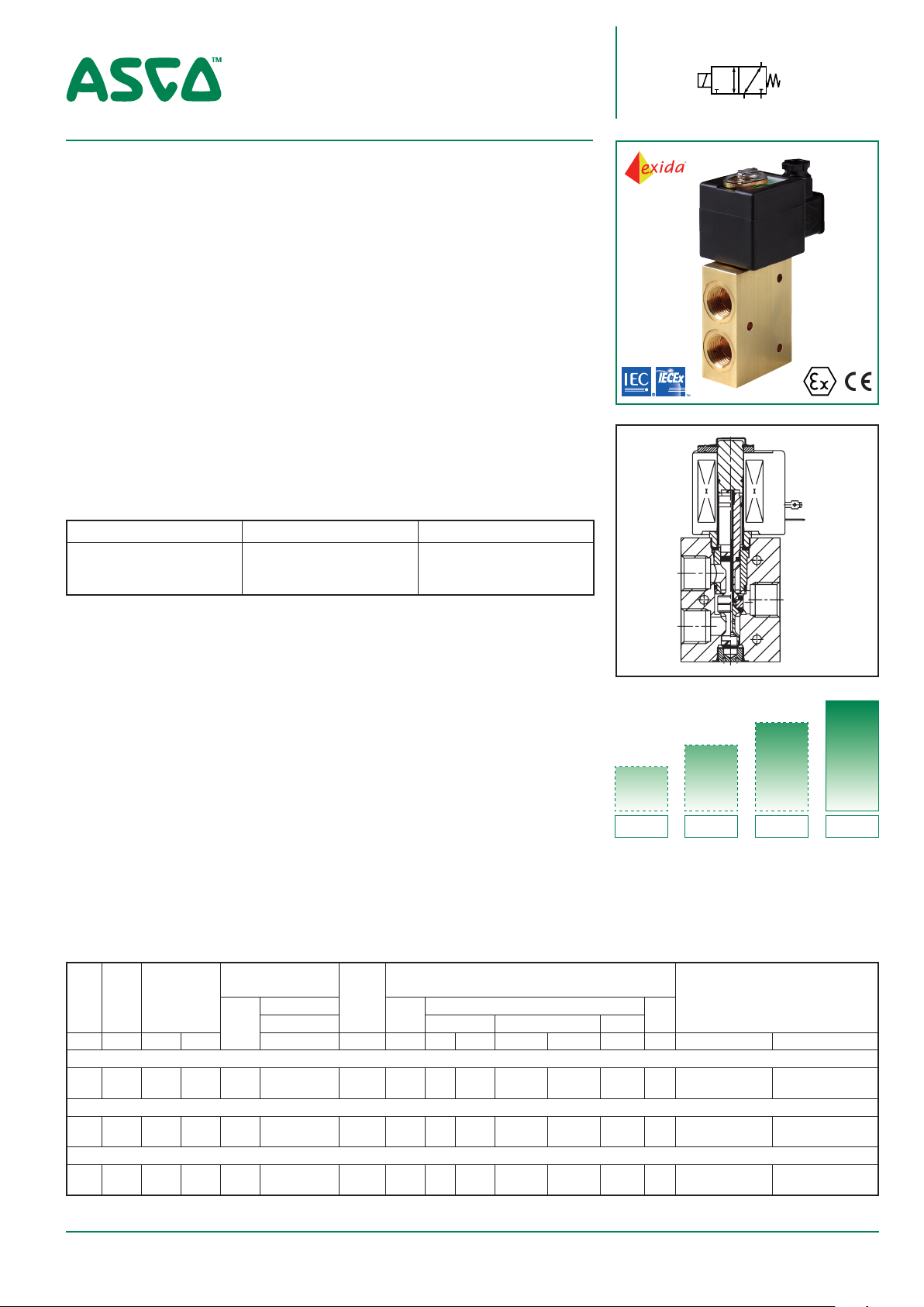
SOLENOID VALVES
2
1
3
direct operated, high flow
balanced poppet
1/4 to 1/2
FEATURES
• The valves are certified according to IEC 61508 Functional Safety data and have
SIL-3 capability (TÜV & Exida certification)
• The solenoid valves are recommended for pilot applications with high flow, wide
pressure ranges and no minimum operating pressure
• Coils used in metal enclosures have class H insulation materials
•
The core movement is guided to ensure optimal alignment. The special low friction
seal accomplishes a balanced construction at the specified temperature and
pressure range at minimum power levels
• Special rider rings eliminate sticking and provide exceptional service life
• No minimum operating pressure required
• Pressure can be applied at any port
• 316L stainless steel construction for highly corrosive atmospheres
• The solenoid valves satisfy all relevant EU directives
• Manual Operators are optional including an under pressure removable type
• Environmental NACE compliant and certified vibration resistant in combination
with WSCR solenoids
GENERAL
Differential pressure 0 - 10 bar [1 bar = 100kPa]
Response times < 100 ms
3/2
U
Series
327
fluids ()
air, inert gas
(1)
Can be limited by the operator ambient temperature range for explosion proof solenoids
temperature range (TS)
- 25 to + 60°C
- 10 to + 90°C
- 50 to + 60°C
(1)
seal materials ()
NBR (nitrile)
FPM (fluoroelastomer)
(F)VMQ ((fluor)silicone)
MATERIALS IN CONTACT WITH FLUID
()
Ensure that the compatibility of the fluids in contact with the materials is verified
Brass body Stainless steel body
Body Brass AISI 316L SS
Stem Stainless steel Stainless steel
Core tube Stainless steel Stainless steel
Core and plugnut Stainless steel Stainless steel
Springs Stainless steel Stainless steel
Seals NBR, FPM or (F)VMQ NBR, FPM or (F)VMQ
Rider ring PTFE PTFE
SPECIFICATIONS
operating pressure
differential (bar)
max. (PS)
min.
air (
~/= ~/= EF NF WSCR
power
level
NEMA
)
7&9
pipe
orifice
size
size
(mm) (m3/h) (l/m)
flow
coefficient
Kv
U - Universal, NBR sealings and poppets
1/4 12 1,5 25,0 0 10 BP 1/2 12 1,5 25,0 0 10 BP -
U - Universal, FPM sealings and poppets
1/4 12 1,5 25,0 0 10 BP 1/2 12 1,5 25,0 0 10 BP -
U - Universal, (F)VMQ sealings and poppets
1/4 12 1,5 25,0 0 10 BP 1/2 12 1,5 25,0 0 10 BP -
Select 8 for NPT ANSI 1.20.3 or Select G for ISO G(228/1) ● Available feature
(2)
Not in combination with WSCR solenoids
prefix optional solenoids
ATEX/IECEx
Ex db Ex eb mb Ex mb
WSCREM PV SC
EM
1
2
3
MP
RP
LP
Not
Available
Low
power
POWER LEVELS - cold electrical holding values (watt)
IP65
-
-
-
-
-
-
Available feature in DC only - Not available
Not
Available
Reduced
power
brass
327A647 327A648
327A607 327A608
327A649 327A650
327A609 327A610
327A645 327A646
327A605 327A606
Not
Available 8W - 14,1W
Medium
power
basic
catalogue
number
(2)
stainless steel
All leaflets are available on: www.asco.com
BP
Basic
power
80021GB-2018/R01
1
Page 2

SERIES 327
PREFIX TABLE
prefix
1 2 3 4 5 6 7
E M Waterproof IP66/67 - Metal enclosure (EN/IEC 60079-7,-18 and -31)* - - -
E T
N F
S C
W P
W S
W S C R Flameproof 316L SS (EN/IEC 60079-0+1+31)* - - W S C R E M Increased Safety / Encapsulated 316L SS (EN/IEC 60079-0+7+18+31)* - - W S E M
W S N F
T
* ATEX/IECEx valves using these solenoids are approved according to EN 13463-1 (non electrical)
Threaded conduit/hole (M20 x 1,5) - - Flameproof - Aluminium (EN/IEC 60079-1, 60079-31)* - - Solenoid with spade plug connector (EN/IEC 60730) - - Waterproof IP67 - Metal enclosure - - Waterproof IP67 - 316 SS enclosure - - -
Waterproof IP66/67 - 316 SS enclosure (EN/IEC 60079-7,-18 and -31)* - - Flameproof - 316L SS (EN/IEC 60079-1, 60079-31)* - - Threaded conduit (1/2" NPT) - - -
X
Other special constructions - - -
description
power level
LP RP MP BP
SUFFIX TABLE
suffix
1 2 3 4 5
V FPM (fluoroelastomer) - - -
C O
M O
M S Screw type manual operator
● Available feature Available feature in DC only -Not available
(1)
Functional Safety certification is not applicable with this feature
(2)
Under pressure removable execution (see page 5)
Epoxy coating on all external surfaces - - Push type manual operator
description
(2)
(1) (2)
power level
LP RP MP BP
- - -
- - -
PRODUCT SELECTION GUIDE
STEP 1
Select the fluid temperature range and
seal material from the general table
on page 1. Select, based on the se-
lected seal material (if applicable), the
basic catalogue number. Also select
the pipe thread identification letter.
Example: G327A607
STEP 2
Select prefix (combination): Select
the appropiate operator from the
prefix table on the left. Select for this
operator in the electrical characteristics table on page 3: the power level
(LP,RP,MP,BP) the type of electrical
enclosure protection and the desired
temperature class.
Warning: the ambient temperature
range of your application may not
exceed the temperature range of
your operator (see also on page 3
the section: Explanation of temperature ranges of solenoid valves).
Example: SC G327A607
OPTIONS & ACCESSORIES
catalogue number
SC 327A605 C117638
SC 327A606 C117638
SC 327A607 C117640
SC 327A608 C117640
SC 327A609 C117640V
SC 327A610 C117640V
SC 327A645 C117638
SC 327A646 C117638
SC 327A647 C117640
SC 327A648 C117640
SC 327A649 C117640V
SC 327A650 C117640V
Select 8 for NPT ANSI 1.20.3 or select G for ISO G(228/1)
(2)
Standard prefixes/suffixes are also applicable to kits
Mounting holes in body
spare part kit no.
~ / =
(2)
mounting bracket
ORDERING EXAMPLES VALVES:
SC 8 327A607 24V / DC
WSEMT G 327A608 MS
NFET G 327A607
WSCREM G 327A608 MS
NF 8 327A645
WS G 327A648 MS
EM 8 327A607
WSNF G 327A608 MS
prefix
pipe thread voltage
basic number suffix
24V / DC
230V / 50 Hz
24V / DC
24V / DC
24V / DC
230V / 50 Hz
24V /
DC
STEP 3
Select suffix (combination) if required.
Refer to the suffix table on page 2,
respect the indicated power level.
Example: VMS
STEP 4
Select voltage. Refer to standard
voltages on page 3.
Example: 230V / 50Hz
STEP 5
Final catalogue / ordering number.
Example:
SC G327A607 VMS 230V / 50 Hz
ORDERING EXAMPLES KITS:
C117640
WSEM C117640 MS
NF C117640
WSEM C117640 MS
prefix
basic number
(1)
Basic kit number applies to SC coil construction
All leaflets are available on: www.asco.com
2
(1)
suffix
80021GB-2018/R01
Page 3

SERIES 327
EXPLANATION OF TEMPERATURE RANGES OF SOLENOID VALVES
Valve temperature range The valve temperature range (TS) is determined by the selected seal material, the temperature
range for proper operation of the valve and sometimes by the fluid (e.g. steam)
Operator ambient temperature range The operator ambient temperature range is determined by the selected power level and the
safety code
Total temperature range The temperature range of the complete solenoid valve is determined by the limitations of both
temperature ranges above
ELECTRICAL CHARACTERISTICS
Coil insulation class H
(1)
(2)
/ F
Electrical safety IEC 60335-1
Standard voltages DC (=) 24V - 48V; Allowable voltage variation ± 10%
AC (~) 24V - 48V - 115V - 230V/50/60Hz; Other voltages are available on request
operator
ambient
temperature
range
(3)
safety code
electrical
enclosure
protection
(EN 60529)
replacement coil / kit
~ =
230V/50/60 Hz
prefix
option
power ratings
inrush
(VA) (VA) (W) (W) (C°)
holding
~ ~ =
hot/cold
Basic power (BP)
SC
SC
WP/WS
WP/WS
WSCR
WSCR
NF/WSNF
NF/WSNF
WSCREM
WSCREM
EM/WSEM
EM/WSEM
(1)
Coils used in metal enclosures have class H insulation materials
(4)
Refer to the dimensional drawings on page 4 and 5
10,0 10,0 10,0 9/10 -40 to +60 EN 60730
14,1 14,1 14,1 11/14 -40 to +90 EN 60730
10,0 10,0 10,0 9/10 -40 to +60 EN 60730
14,1 14,1 14,1 11/14 -40 to +90 EN 60730
8,0 8,0 8,0 6,4/8 -60 to +25/40/60
10,0 10,0 10,0 9/10 -60 to +25/60/90
10,0 10,0 10,0 9/10 -60 to +40/60
14,1 14,1 14,1 11/14 -60 to +40/60/90
8,0 8,0 8,0 6,4/8 -60 to +25/40/60
10,0 10,0 10,0 9/10 -60 to +25/60/90
10,0 10,0 10,0 9/10 -40 to +40/60
14,1 14,1 14,1 11/14 -40 to +40
II2G Ex db IIC Gb T6/T5/T4, II2D Ex t IIIC Db
II2G Ex db IIC Gb T5/T4/T3, II2D Ex t IIIC Db
II2G Ex db IIC Gb T6/T5, II2D Ex tb IIIC Db
II2G Ex db IIC Gb T6/T5, II2D Ex tb IIIC Db
II2G Ex eb mb IIC Gb T6/T5/T4, II2D Ex tb IIIC Db
II2G Ex eb mb IIC Gb T5/T4/T3, II2D Ex tb IIIC Db
II2G Ex eb mb IIC Gb T4/T3, II2D Ex tb IIIC Db IP66/67, steel /SS
II2G Ex eb mb IIC Gb T3, II2D Ex tb IIIC Db IP66/67, steel /SS
(2)
Encapsulated (open) coils have class F insulation standard
- Not available
IP65, moulded
IP65, moulded
IP67, steel /SS
IP67, steel /SS
IP66/67, SS
IP67, alu./SS 400962-197 400961-342 04
IP66/67, alu./SS
IP66/67, alu./SS
IP66/67, SS
IP66/67, SS
(3)
Temperature range can be limited by sealings
400924-197 400923-342 01
400924-697 400923-642 01
400921-197 400911-342 02
400921-697 400911-642 02
400962-497 400961-042 04
400921-197 400911-342 03
400921-697 400911-642 03
400962-497 400961-042 04
400962-197 400961-342 04
400921-197 400911-342 02
400921-697 400911-642 02
ELECTRICAL CONNECTIONS
prefix connection
SC
WP, WS, EM, WSEM M20 plastics cable gland for cables with an outer diameter from 7 to 12 mm.
WSCREM M20 316 SS cable gland for cables with an outer diameter from 7,2 to 11,7 mm.
NF, WSNF, WSCR 1/2” NPT threaded cable entry. Enclosures are supplied without cable gland
NFET, WSNFET M20 x 1,5 threaded cable entry. Enclosures are supplied without cable gland
Spade plug connector with cable gland EN175301-803A (ISO 4400) for cables with an outer
diameter from 6 to 10 mm
24V/DC
type
(4)
ADDITIONAL OPTIONS
• Manual operator MO (push type) and MS (screw type)
• 3/8” pipe thread execution
• 1/2” NPT (prefix “T”) and M20 x 1,5 (prefix “ET”) conduits (aluminium or 316 SS) available for steel solenoid housing
• Solid state components for peak voltage suppression and/or rectification
• For manual reset type see page PIC-11-25
• Manual Operators are available as shown on page 5
• Class H insulation for encapsulated coils
• Material certification like EN 10204 3.1 on the 316L Stainless Steel bodies are available on request
INSTALLATION
• Multi language installation/maintenance instructions are included with each valve
• The solenoid valves can be mounted in any position without affecting operation
• The mounting holes are provided in the valve body
• Threaded pipe connection identifier is 8 = NPT (ANSI 1.20.3); G = G (ISO 228/1)
• Declarations of conformity are available on request
All leaflets are available on: www.asco.com
80021GB-2018/R01
3
Page 4

DIMENSIONS (mm), WEIGHT (kg)
A
D
TYPE 01: TYPE 02:
Epoxy moulded
SC: IEC 60335-1 / ISO 4400
SERIES 327
Metal, epoxy coated / AISI 316L SS
WP / WS : IEC 60335-1
EM / WSEM : EN/IEC 60079-7+18+31
327A605 / A606 / A607 / A608 / A609 / A610
327A645 / A646 / A647 / A648 / A649 / A650
360°
TYPE 03: TYPE 04:
Aluminium, epoxy coated / AISI 316L SS
NF / WSNF: EN/IEC 60079-1+31
327A605 / A606 / A607 / A608 / A609 / A610
327A645 / A646 / A647 / A648 / A649 / A650
Manual operator
(MO/MS) execution
327A605 / A606 / A607 / A608 / A609 / A610
327A645 / A646 / A647 / A648 / A649 / A650
360°
AISI 316L SS
WSCR : EN/IEC 60079-0, 60079-1, 60079-31
WSCREM : EN/IEC 60079-0, 60079-7, 60079-18,
EN/IEC 60079-31
327A605 / A606 / A607 / A608 / A609 / A610
327A645 / A646 / A647 / A648 / A649 / A650
Manual operator
(MO/MS) execution
Manual operator
(MO/MS) execution
360°
type prefix/option power level
G
H
360°
1
3
B
C
24
F
E
Ø5.5
48
62
32
46
J
A B C D E F G H J K L M N
Manual operator
(MO/MS) execution
M
01 SC BP 50 30 135 95 54 32 100 23 70 60 38 40 54 1,6 kg
02
WP, WS, EM/WSEM
NF BP 97 30 165 115 54 32 102 55 60 100 38 40 54 2,4 kg
03
WSNF BP 97 30 165 115 54 32 102 55 60 100 38 40 54 3,8 kg
04
WSCR, WSCREM BP 92 30 167 128 54 32 116 75 60 - 38 40 54 3,2 kg
BP 75 30 140 95 54 120 80 60 38 40 54 - - 1,6 kg
2
L
N
weight
All leaflets are available on: www.asco.com
4
80021GB-2018/R01
Page 5

SECTIONAL DRAWINGS
REF A.
Manual Operator (MS*) Manual Operator (MO) Removable Manual Operator (MS*) / (MO)
SERIES 327
1
3
Suffix MS* Suffix MO
REMOVABLE MO / MS TOOL
1
2
2
3
1
2
3
adapter
Adapter
plug
29 mm
plug
Tool to remove plug. Kit no.: C325325
* MS type is not covered in the Functional Safety (SIL) certification
EXHAUST PROTECTOR
pipe
size
1/4
1/2
thread
brass nickel plated 316L stainless steel
ISO 228/1 131875-001 131875-014
NPT 131875-002 131875-015
ISO 228/1 131875-005 131875-012
NPT 131875-006 131875-013
part number
mesh\filtering
100 - 200 µm 16 mm
100 - 200 µm 23 mm
wrench size
(REF A.)
Mounted adapter use TPL 26710
Removable Manual Operator Kit number
MS type*
MO type
Adapter type
C325324
C325323
C325410
All leaflets are available on: www.asco.com
80021GB-2018/R01
5
Page 6

All leaflets are available on: www.asco.com
6
PIC-02-0055-GB -- Availability, design and specifications are subject to change without notice. All rights reserved.
80021GB-2018/R01
 Loading...