

Page 1
INSTALLATION AND MAINTENANCE INSTRUCTIONS
INSTRUCTIONS D’INSTALLATION ET DE MAINTENANCE
INBETRIEBNAHME - UND WARTUNGSANLEITUNG
INSTRUCCIONES DE PUESTA EN MARCHA Y MANTENIMIENTO
INSTRUZIONI DI MESSA IN SERVIZIO E MANUTENZIONE
ALGEMENE INSTALLATIE- EN ONDERHOUDSINSTRUCTIES
INSTALLASJONS- OG VEDLIKEHOLDSINSTRUKSER
INSTALLATIONS- OCH UNDERHÅLLSINSTRUKTIONER
ASENNUS - JA HUOLTO-OHJEET
INSTALLATIONS - OG VEDLIGEHOLDSANVISNINGER
INSTRUÇÕES DE INSTALAÇÃO E MANUTENÇÃO
ΟΔΗΓΙΕΣ ΤΟΠΟΘΕΤΗΣΗΣ ΚΑΙ ΣΥΝΤΗΡΗΣΗΣ
POKYNY PRO INSTALACI A ÚDRŽBU
INSTRUKCJA MONTAŻU I KONSERWACJI
TELEPÍTÉSI ÉS KARBANTARTÁSI ÚTMUTATÓ
ИНСТРУКЦИЯ ПО УСТАНОВКЕ И ОБСЛУЖИВАНИЮ
ОРНАТУ ЖƏНЕ ҚЫЗМЕТ КӨРСЕТУ НҰСҚАУЛАР
3/2 SLOW-START
QUICK EXHAUST VALVES
EN
FR
DE
ES
IT
NL
NO
SE
FI
DK
PT
GR
CZ
PL
HU
RU
KZ
651 - 652 - 653
F°
F°
160
160
150
150
140
140
130
130
120
120
110
110
100
100
90
90
80
80
70
70
60
60
50
50
40
40
30
30
20
20
10
10
0
0
-10
-10
C°
C°
70
70
60
60
50
50
40
40
30
30
20
20
10
10
-10
-10
-20
-20
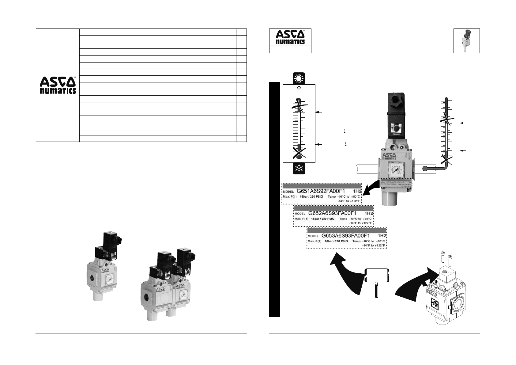
3/2 SLOW-START
QUICK EXHAUST VALVES
651 - 652 - 653
▼ ▼
NBR
C°
F°
210
200
190
180
+50°C
+50°C
651/652 = 145 PSIG (10 bar)
653 = 230 PSIG (16 bar)
0
0
max.
651/652/653 = 55 PSIG (3,8 bar)
-10°C
-10°C
min.
(bar)
P1
170
160
150
140
130
120
110
100
110
100
90
80
60
+50°C
50
40
90
30
80
70
20
60
50
10
40
30
20
10
-10
0
-10
-20
-10°C
0
651
1/8 - 1/4
1/2 - 3/4 - 1
652
1/4 - 3/8 - 1/2
2 3
653
OPERATING CONDITIONS
508608-001 / B
Availability, design and specifi cations are subject to change without notice. All rights reserved.
OPTIONS:
&
FKM/FPM
-20°C
+50°C/+80+C
508608-001508608-001
Page 2
651 - 652 - 653
3/2 SLOW-START
QUICK EXHAUST VALVES
651 - 652 - 653
▼ ▼
651 - 652 - 653
3/2 SLOW-START
QUICK EXHAUST VALVES
651 - 652 - 653
▼ ▼
&
P651AT504958001
651 ►
NBR
FPM/FKM
652 ►
653 ►
651 ►
652 ►
653 ►
P652AT502466001
P653AT507291001
P651AT504958003
P652AT502466003
P653AT507291003
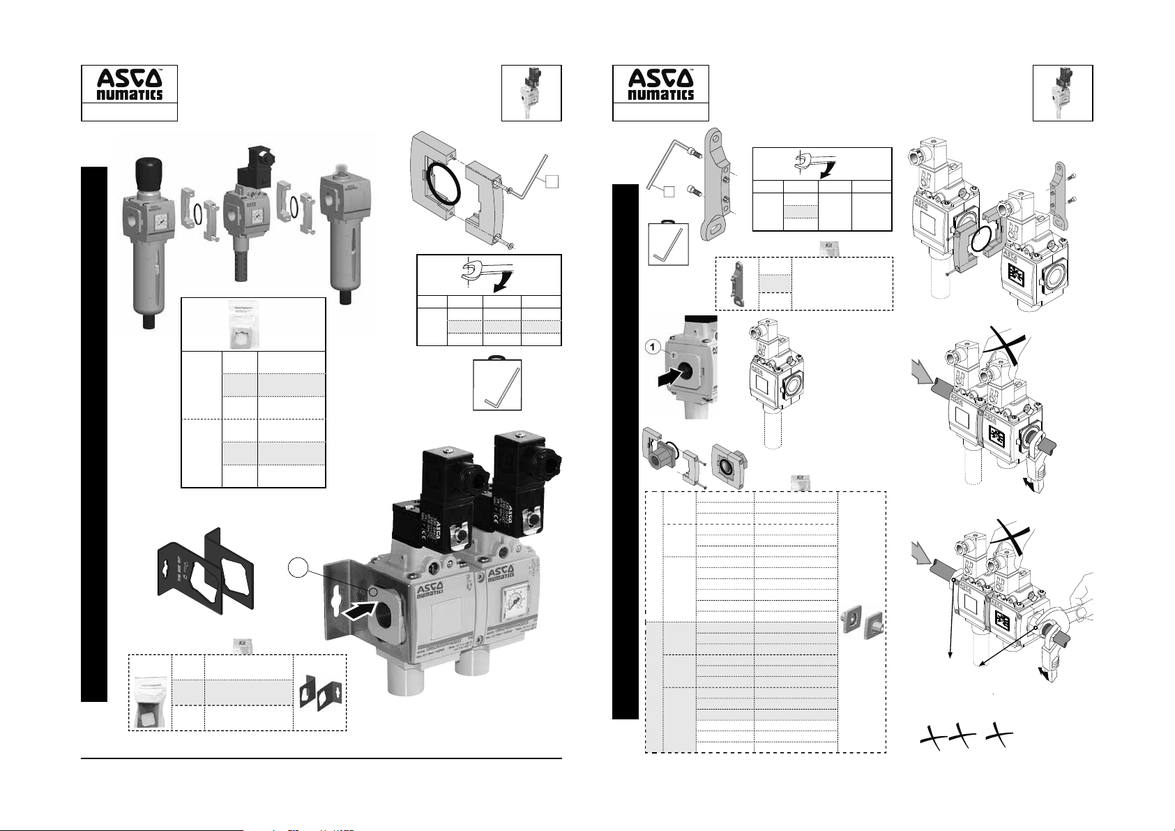
MOUNTING / ASSEMBLING UNITS
&
P651AT503860001
651 ►
&
P652AT503860002
652 ►
P653AT503860003
653 ►
A
B
4
items N.m
651 ►
B
652 ►
653 ►
F
Inch.pounds
4,2±0,2 37±2
&
651 ►
652 ►
653 ►
items N.m
A
651 ►
652 ►
653 ►
1,13±0,2 10±2
1,9±0,2 17±2
2,9±0,2 25±2
651 = 2,5
652 = 3
653 = 4
F
Inch.pounds
MOUNTING
1/4 NPTF
1/4 ISO 228/1-G
651 ►
1/4 ISO 7/1 Rc
1/2 NPTF
1/2 ISO 228/1-G
652 ►
653 ►
651 ►
652 ►
653 ►
1/2 ISO 7/1 Rc
1 NPTF
1 ISO 228/1-G
1 ISO 7/1 Rc
1-1/4 NPTF
1-1/4 ISO 228/1-G
1-1/4 ISO 7/1 Rc
1/4 NPTF
1/4 ISO 228/1-G
1/4 ISO 7/1 Rc
1/2 NPTF
1/2 ISO 228/1-G
1/2 ISO 7/1 Rc
1 NPTF
1 ISO 228/1-G
1 ISO 7/1 Rc
1-1/4 NPTF
1-1/4 ISO 228/1-G
1-1/4 ISO 7/1 Rc
4
4
4
NBR
FPM/
FKM
T651AT504959001
T651AT504959002
T651AT504959003
T652AT502468001
T652AT502468002
T652AT502468003
T653AT507292001
T653AT507292002
T653AT507292003
T653AT507292019
T653AT507292020
T653AT507292021
T651AT504959007
T651AT504959008
T651AT504959009
T652AT502468007
T652AT502468008
T652AT502468009
T653AT507292007
T653AT507292008
T653AT507292009
T653AT507292027
T653AT507292026
T653AT507292021
P699AT502467001
651
1/8
1/4
&
1/4
652
3/8
1/2
1/2
3/4
1
&
653
&
&
651
1/4
&
&
1/8
652
1/2
&
1/4
3/8
653
&
1
3/4
508608-001508608-001
Page 3
FRL ASSEMBLY
651 - 652 - 653
651 - 652 - 653
Assembly: All ports on the device that may come in contact with pressurized fl uids must be connected to a conduit or an associated component (example: exhaust
silencer, etc.). Stamped brackets and nut are not to be used to support product during installation of pipe or fi ttings.
Use: Personnel working with the components must be familiar with electric controls, such as redundancies and feedback (electronic controls), where applicable.
EN
Environment: In order to prevent noise nuisance due to system purging by certain components (especially with compressed air), it is recommended to use noise
reduction systems.
Montage : Tous les orifi ces de l'appareil pouvant être en contact avec le fl uide sous pression doivent être raccordés à une canalisation ou à un composant associé
(exemple : silencieux d'échappement, etc.). L'installation des supports et fi xations ne doivent se faire qu'une fois les tuyauteries installées.
Utilisation : Le personnel intervenant sur certains de ces composants doit être familiarisé avec la commande électrique, par ex. redondances et le cas échéant le
FR
DE
ES
IT
NL
NO
SE
FI
DK
PT
GR
CZ
PL
HU
RU
KZ
retour d’information (commandes électroniques).
Environnement : Afi n d'éviter les nuisances sonores dues à la purge de capacité (notamment en air comprimé) par certains composants, il est préconisé d'utiliser des systèmes de
Montage: Alle Anschlüsse der Komponente, die mit dem unter Druck stehenden Medium in Berührung kommen können, sind mit der dazugehörigen Verrohrung oder einem dazugehörigen Gerät zu
Einsatz: Das mit Arbeiten an den Komponenten betraute Personal muss mit elektrischer Steuerungstechnik wie Redundanzen und, gegebenenfalls, Rückkopplungen (elektronische
Umweltschutz: Um die von manchen Komponenten durch die Entlüftung verursachte Geräuschentwicklung (insbesondere bei Druckluft) zu vermeiden, wird eine Schalldämpfung empfohlen.
Montaje: Todos los orifi cios del aparato susceptibles de entrar en contacto con el fl uido presurizado deben estar conectados a un conducto o a un componente asociado (ejemplo:
Utilización: El personal que maneje los componentes debe tener conocimientos sobre controles eléctricos, como las redundancias y, si se diera el caso, sobre el retorno de
Medio ambiente: Para evitar las molestias del ruido de las purgas de capacidad (especialmente con aire comprimido) causadas por determinados componentes, se reco-
Montaggio: È necessario che tutte le connessioni del dispositivo che entrano in contatto con il fl uido pressurizzato siano collegati a un condotto o a un componente associato
Utilizzo: È necessario che il personale che utilizza i componenti conosca bene i controlli elettronici, come le ridondanze e i principi dei feedback (controlli elettronici).
Ambiente: Per evitare disturbi sonori dovuti allo scarico di determinati componenti (soprattutto con l'aria compressa), si consiglia di utilizzare sistemi di riduzione della rumorosità.
Assemblage: Alle poorten op het apparaat die in contact kunnen komen met onder druk staande media moeten worden aangesloten op een leiding of een daarbij behorend onderdeel (bijvoorbeeld
Gebruik: De personen die met deze componenten werken, moeten op de hoogte zijn van de geldende eisen ten aanzien van elektrische (elektronische) regelaparatuur zoals
Omgeving: Teneinde geluidsoverlast als gevolg van capaciteitsreiniging (met name met behulp van perslucht) door bepaalde onderdelen te voorkomen, raden wij u aan gebruik
Montering: Alle portene på enheten som kan komme i kontakt med trykkvæske, må være tilkoblet en ledning eller en tilbehørskomponent (for eksempel en avgassdemper
Bruk: Personalet som arbeider med komponentene, må være fortrolig med den elektroniske styringen, for eksempel redundans og feedback der dette er aktuelt
Omgivelser: For å unngå støy som oppstår når innholdet i enkelte komponenter tømmes ut (spesielt når det gjelder trykkluft), anbefales bruk av støyreduksjonssystemer.
Montering: Alla öppningar på apparaten som kan komma i kontakt med tryckfl öden ska vara anslutna till en ledning eller tillbehörskomponent (till exempel: avgasdämpare
Användning: Den personal som utför arbetet på vissa av komponenterna ska vara förtrogna med den elektriska styrningen, till exempel redundans och i förekommande
Miljö: För att undvika oljud som uppstår när vissa komponenter tömmer innehållet (i synnerhet med tryckluft), ska man använda ljuddämpande system.
Kokoaminen: Kaikkiin laitteessa oleviin aukkoihin, jotka voivat joutua kosketuksiin paineenalaisen nesteen kanssa, on liitettävä putki tai jokin komponentti (esimerkki:
Käyttö: Komponentteja käsittelevien henkilöiden täytyy tuntea soveltuvin osin elektroniset säädöt, kuten redundanssit ja takaisinkytkentä (elektroniset säädöt).
Ympäristö: Jotta vältettäisiin joidenkin komponenttien aiheuttamat meluhaitat (erityisesti paineilman vuoksi), on suositeltavaa käyttää äänenvaimennusjärjestelmiä.
Samling: Alle de porte på enheden, som kan komme i kontakt med væsker under tryk, skal være forbundet med andre rør eller en tilsluttet komponent, f.eks. en lyd-
Brug: De personer, som arbejder med komponenterne, skal have erfaring med elektronikarbejde, f.eks. statisk elektricitet og tilbagekobling (elektroniske kontrolsystemer).
Omgivelser: For at undgå lydgener, når visse komponenter arbejder på højtryk (især med komprimeret luft), anbefales det at installere systemer til støjreduktion.
Montagem: Todas as portas do dispositivo que possam entrar em contacto com o fl uido sob pressão têm de ser ligadas a uma tubagem ou a um componente associado (por
Utilização: O pessoal que trabalha com os componentes tem de estar familiarizado com controlos electrónicos, tais como redundâncias e feedback, se for o caso (controlos electrónicos).
Ambiente: Para evitar a poluição sonora, devido à purga de capacidade (especialmente com ar comprimido), por determinados componentes, é aconselhável utilizar sistemas
Ухнбсмпльгзуз: ¼лет пй иэсет фзт ухукехЮт рпх хрЬсчей ендечьменп нб Эсипхн уе ербцЮ ме фп хгсь хрь рЯеуз рсЭрей нб еЯнбй ухндедемЭнет уе Энб ущлЮнб Ю уе кЬрпйп Ьллп
ЧсЮуз: Фп рспущрйкь рпх бучплеЯфбй ме фб еобсфЮмбфб рсЭрей нб гнщсЯжей фз лейфпхсгЯб фщн злекфспнйкюн ухуфзмЬфщн елЭгчпх, ьрщт фйт ецедсеЯет кбй фзн бнбфспцпдьфзуз,
РесйвЬллпн: Гйб нб брпцехчипэн пй енпчлзфйкпЯ иьсхвпй рпх рспкблпэнфбй льгщ фпх кбибсйумпэ фпх рхкнщфЮ (ейдйкЬ ме рерйеумЭнп бЭсб) брь псйумЭнб еобсфЮмбфб, убт
Montáž: Všechny přípojky na zařízení, které se mohou dostat do kontaktu s kapalinami pod tlakem, musejí být připojeny k vedení nebo k připojené součásti (například:
Používání: Osoby pracující s těmito součástmi musejí znát elektrické ovládací prvky, jako jsou redundance a zpětné vazby (elektronické ovládání).
Pracovní prostředí: Aby se zabránilo zbytečnému hluku v důsledku odvzdušňování systému pomocí určitých součástí (obzvláště v případě stlačeného vzduchu),
Montaż: wszystkie złącza urządzenia, które mogą wejść w kontakt z cieczami pod ciśnieniem, musza być podłączone do przewodów lub innego komponentu (przykład:
Użytkowanie: personel pracujący z komponentami musi być obeznany z mechanizmami sterowania elektrycznego, takimi jak redundancja i sprzężenie zwrotne
Otoczenie: w celu zapobiegania uciążliwemu hałasowi, szczególnie w systemach uwalniających sprężone powietrze, zaleca się stosowanie systemów redukcji hałasu.
Összeszerelés: A készülék minden olyan csatlakozóját, amely nyomás alatt lévő folyadékkal érintkezhet, megfelelő védőcsőhöz vagy alkatrészhez kell rögzíteni
Használat: Az alkatrésszel dolgozó személynek tisztában kell lennie az elektronikus vezérlések, redundanciák és gerjedés (elektronikus v ezérlés) fogalmával.
Környezet: A berendezés egyes részegységei (különösen a sűrített levegővel működő egységek) által keltett zajszennyezés csökkentése érdekében javasolt a
Сборка: Все порты устройства, которые могут вступать в контакт с давлением жидкости должен быть соединен с трубопроводом или соответствующего компонента (например, глушитель и т.д.). Запрещается использовать штампованные кронштейны и гайки для поддержки изделия во время установки труб или фитингов.
Использование: Персонал, работающий с компонентами должны быть знакомы с электрическим управлением, например, увольнений и обратной связи (электронные
системы управления), где это применимо.
Окру
рекомендуется использовать системы сокращения шума.
Жинақ: Құрылғыдағы қысымдалған сұйықтықтармен байланысқа түсуі мүмкін барлық порттарды құбыр желісіне немесе тиісті құрамдасқа (мысалы,
Пайдалану: Құрамдастармен жұмыс істей тін қызметкерлер резервтеу жəне кері реакция (электрондық басқару) сияқты (қолданылса) э
Қоршаған орта: Жүйені белгілі бір құрамдастармен (əсіресе сығылған ауамен) үрлеп тазалау кезінде шудың əсерінен қорғау үшін шуды азайту
réduction de bruit.
verbinden (z.B. Schalldämpfer usw.). Gestanzte Befestigungen mit Schraubenmutter eignen sich nicht für die Halterung des Produkts bei der Installation des Rohrs oder der Fassungen.
Steuerungen) vertraut sein.
silenciosos de escape, etc.) Los soportes y la tuerca marcados no deben utilizarse para apoyar el producto durante la instalación de las tuberías o los acoplamientos.
información (controles electrónicos).
mienda utilizar sistemas de reducción del ruido.
(esempio: fi ltro-silenziatore, ecc.) Le squadre ed i dadi forgiati non devono essere utilizzati per il supporto del prodotto durante l’installazione del tubo o dei raccordi.
een afblaasfi lter-demper o.i.d.). Voor ondersteuning van het product tijdens de installatie van leidingen of fi ttingen mogen geen voorgestanste beugels of moeren worden gebruikt.
redundante systemen of regelingen met terugkoppeling, en van hun toepassingen .
te maken van geluidsverminderingssystemen.
e.l.). Stemplede braketter og bolter skal ikke brukes til å støtte produktet under installasjon av rør eller fester.
(elektroniske styringsverktøy).
etc.) De stansade byglarna och muttern får inte användas till att stödja produkten under montering av rör eller kopplingar.
fall informationsretur (elektronisk styrning).
äänenvaimennin, jne.) Puristekiinnikkeitä ja uraa ei saa käyttää tuotteen tukemiseen putken tai liittimien asennuksen aikana.
dæmper. De udstansede konsoller og fastgørelsesringen må ikke bruges som understøttelse af produktet under montering af rør eller fi ttings.
exemplo: silenciador de escape, etc.). Não deve utilizar a porca e os suportes estampados para suportar o produto durante a instalação do tubo ou dos encaixes.
de redução de ruído.
еоЬсфзмб (рбсЬдейгмб: уйгбуфЮсб еоЬфмйузт кфл.). Τα παραγόμενα σε πρέσα μπρακέτα και το παξιμάδι δεν προορίζονται για την υποστήριξη του προϊόντος κατά την εγκατάσταση σωλήνων ή στηριγμάτων.
ецьупн чсейбуфеЯ (злекфспнйкЭт лейфпхсгЯет).
ухнйуфпэме нб чсзуймпрпйЮуефе ухуфЮмбфб меЯщузт фпх ипсэвпх.
tlumič výfuku, atd.). Lisované držáky a matice se nesmí použít na podporu produktu při instalaci potrubí nebo armatury.
doporučujeme používat systémy tlumení hluku.
tłumik wylotowy itp.). Wsporniki tłoczone i nakrętki nie mogą być stosowane w celu podpierania produktu podczas montażu rur lub złączy.
(sterowanie elektroniczne), o ile ma to zastosowanie.
(például: kipufogódob stb.). A lepecsételt keretek és anyák nem használhatók a termék támogatására a cső vagy a szerelvények telepítése során.
zajcsökkentő berendezések használata.
жающая среда: В целях предотвращения шума неприятность из-за системы продувки некоторыми компонентами (особенно с помощью сжатого воздуха),
шығару бəсеңдеткіші, т.б.) жалғау қажет. Тесігі бар кронштейндер жне гайка бырды немесе фитингілерді орнату барысында німді тіреу шін пайдаланылмауы керек.
басқару элементтерімен таныс болуы қажет.
жүйелерін пайдаланған жөн.
▼ ▼
6 7
лектрлік
651 - 652 - 653
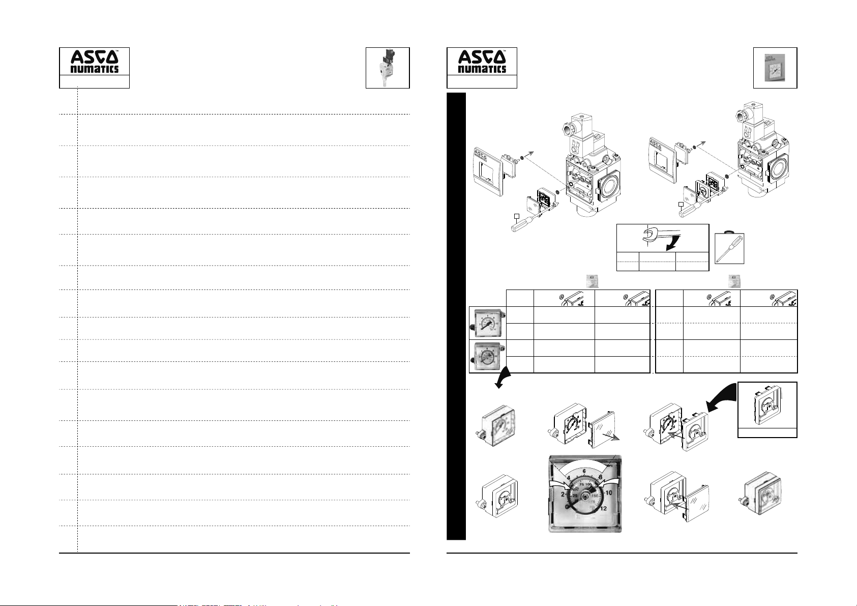
GAUGES
12
QUICK EXHAUST VALVES
f
NBR
0-12 bar
M699AG438047001 M699AG438047013
0-175 PSIG
M699AG438047004 M699AG438047016
0-12 bar
M699AG438047007 M699AG438047019
0-175 PSIG
M699AG438047010 M699AG438047022
O
R
T
N
O
C
4
5
3/2 SLOW-START
651 - 652 - 653
▼ ▼
f
F
A
L
R
&
FPM/FKM
E
A
items N.m
C 0,45 ±0,1 4 ±1
Inch.pounds
0-25 bar M699AG438047003 M699AG438047015
0-375 PSIG M699AG438047006 M699AG438047018
0-25 bar M699AG438047009 M699AG438047021
0-375 PSIG M699AG438047012 M699AG438047024
3
67
NBR
&
FPM/FKM
&
M699AG500179001
508608-001508608-001
Page 4
651 - 652 - 653
Rc 1/8
NPTF 1/8
3/2 SLOW-START
QUICK EXHAUST VALVES
651 - 652 - 653
▼ ▼
2
3/2 SLOW-START
QUICK EXHAUST VALVES
651 - 652 - 653
3
651 - 652 - 653
▼ ▼
2
3
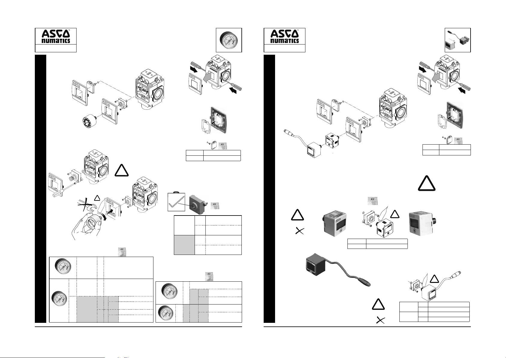
GAUGES
0 .. 12 bar (0..174 psig)
0-10 bar
(0-145 PSIG)
0-10 bar
(0-145 PSIG)
0 .. 12 bar
(0..174 psig)
0-8 bar
(0-125PSIG)
0 .. 11 bar
0..160 psig
!
Ø50
Ø40
Ø40
Ø50
1/8
565™
®
LOCTITE
2
3
Rc
1/8
US
1/8
NPTF
Rc
1/8
US
1/8
NPTF
1
1
23
Thread Sealant with Tefl on is
!
recommended: LOCTITE
1
&
34300062
5
3/16”
NPTF 1/8
®
565™
Rc 1/8
US
NBR
FPM/FKM
1
2
1
M699AG503396001
M699AG503396002
&
M699AG440510002
NBR
M699AG440510004
FKM
FPM
M699AG440510001
NBR
M699AG440510003
FKM
FPM
&
GAUGES
0-145 PSIG Æ bar,MPa, Kgf/cm
!
0..+50°C
FKM / FPM
&
US ►
US ►
34300063
M699AG511766001
Rc
1/8
M699AG511763001
1/8
NPTF
RA300A
Rc
1/8
214-118A
1/8
NPTF
P max. 15 bar (217 PSIG)
12..24 VDC
34300041
214-153A
214-103A
M699AG511765001
M699AG511762001
8 9
0 .. 25 bar (0..360 psig)
Ø50
Ø40
0 .. 20 bar
0..300 psig
1
1
2
1
2
3
1/8
NBR
FPM/FKM
1
M699AG503396001
M699AG503396002
&
!
2
1/8 Rc
1/8 NPTF
&
LOCTITE
M699AG504650002
M699AG504650001
4 pin
!
0..+50°C
FKM / FPM
Thread Sealant with Tefl on is
recommended: LOCTITE
565™
®
!
1/8 Rc
1/8 NPTF
NPN
PNP
NPN
PNP
®
LOCTITE
565™
®
!
DPS280NRQ8
DPS280PRQ8
DPS280NNQ8
DPS280PNQ8
565™
M8
508608-001508608-001
Page 5
651 - 652 - 653
189 Series
Without
manual operator
190 Series
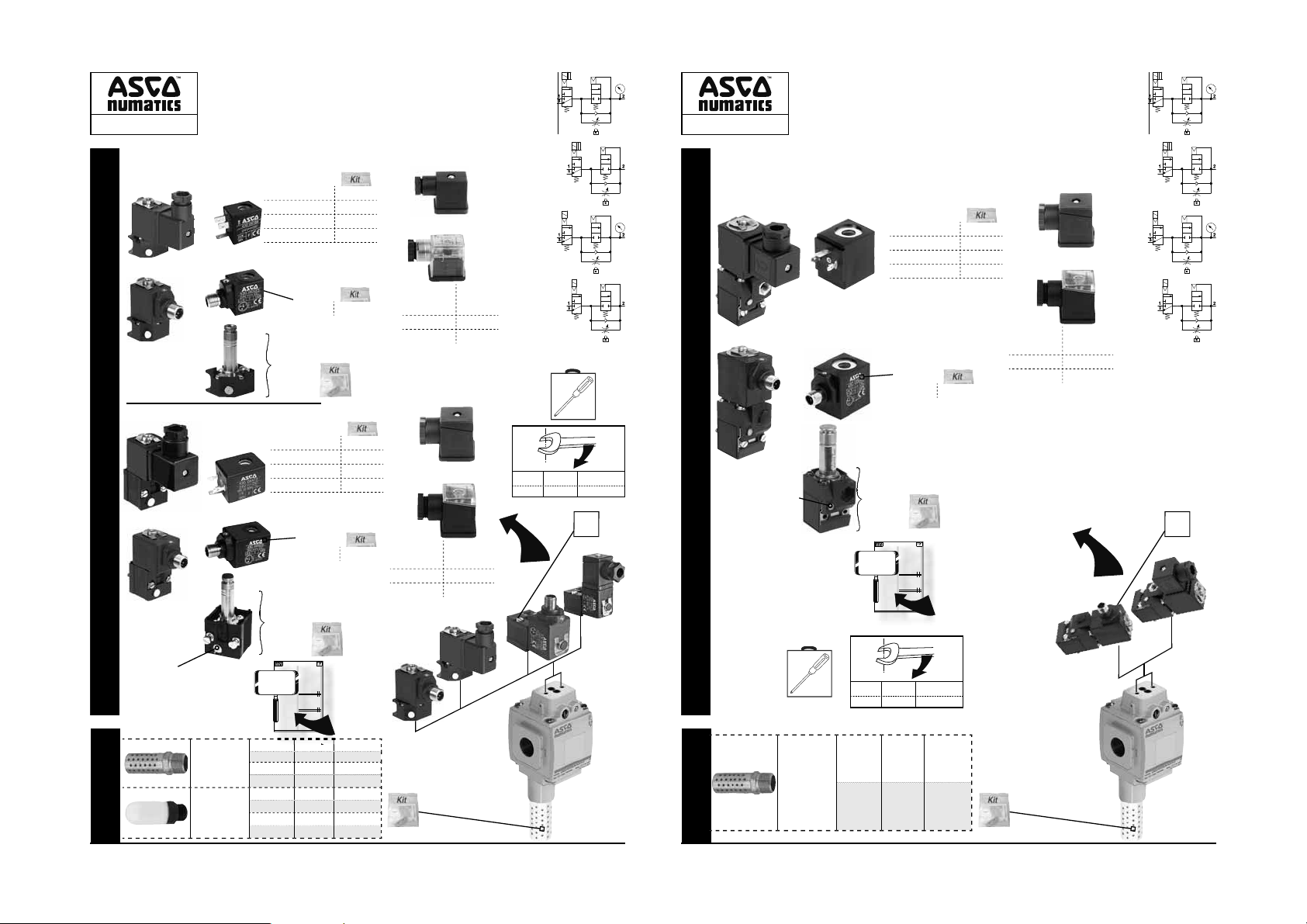
SPARE PARTS KITSSPARE PARTS KITS (DISASSEMBLY / REASSEMBLY)
3/2 SLOW-START
QUICK EXHAUST VALVES
651 - 652
ISO 15218 (CNOMO, size 30) interface
24 V AC 50/60 Hz
115 V AC 50/60 Hz
230 V AC 50/60 Hz
24 V DC
24 V DC (M12)
18990007
24 V AC 50Hz
115 V AC 50/60 Hz
230 V AC 50/60 Hz
24 V DC
24 V DC (M12)
19090005
19090017
▼ ▼
&
43004416
43004419
43004422
43004166
&
43005523
&
&
43004469
43004471
43004472
43004473
&
43005525
&
6-8 mm
88122404
6-8 mm
+ LED
24 V 50/60 Hz
24 V DC
88122405
115 50 Hz 88122407
230 50/60 Hz 88122410
6-10 mm
88122602
8-10 mm
24 V 50/60 Hz
24 V DC
88122603
115 50 Hz 88122605
230 50/60 Hz 88122608
items N.m
Inch.pounds
H 1,9±0,2 17±2
H
3/2 SLOW-START
QUICK EXHAUST VALVES
651 - 652 - 653
ISO 15218 (CNOMO, size 30) interface
192 Series
24 V AC 50Hz
115 V AC 50/60 Hz
230 V AC 50/60 Hz
24 V DC
24 V DC (M12)
F
manual operator:
SPARE PARTS KITSSPARE PARTS KITS (DISASSEMBLY / REASSEMBLY)
19291010 = without
19291012 = impulse
19291010
19291012
DESCRIPTION
This assembly provides
the two following main functions:
- Pneumatic system venting.
- Gradual pressurization after an outage leading to
venting of the system.
SHUT-OFF VALVE
The 3/2 NC shut-off valve, controlled by a solenoid valve
of the CNOMO pad-mounting type, vents the system
by de-energising the solenoid valve.
SOFT-START DEVICE
Upon pressurization, when the soft-start device is
in its initial position, an adjustable air flow ensures
gradual filling of the downstream circuit, so that the
actuators move slowly. The transition to the full flow
position depends on which of the following soft-start
devices is chosen:
- AUTOMATIC SOFT-START DEVICE
Automatic switch-over to the full flow position as soon
as the downstream pressure reaches
supplied pressure (upstream pressure). Operating cycles
take place at normal speed thereafter.
The soft-start device remains in the full flow position as
long as the upstream pressure is maintained.
The device returns into its initial position when the air
supply is cut off.
- SOLENOID/AIR CONTROLLED SOFT-START DEVICE
This device, which complies with technical CNOMO
specifications (E05.03.135.N), can be used to gradually
19..35
feed air into the system whenever restarting after a
shutdown or a pressure cut-off. The system is slowly
returned into the end-of-cycle position. As soon as this
condition is reached, the solenoid pilot valve is energised
in accordance with the automatic control specified by
the user. The soft-start device then switches to the full
flow position allowing the subsequent operating cycles to
take place at normal speed.
be kept energised under normal operating conditions.
Any de-energization of the solenoid pilot valve sets
the soft-start device into the metered flow position.Any
de-energization of the solenoid valve sets the soft-start
device to the low flow position.
Note: In both soft-start device versions, the filling rate,
i.e. the pressure build-up in the downstream circuit, is
adjusted by means of a fine-thread screw which can be
locked to prevent un-authorised adjustment of regulated
pressure.
Manual override on solenoid valves: The assembly can only be piloted with solenoid valves without
manual override or with a non-locking manual override
(impulse-type).
MOUNTING AND OPERATING INSTRUCTIONS
- The shut-off and soft-start valve assembly must be
mounted as described above before the lubricator.
Make sure there is no oil.
- Do not obstruct exhaust port 3 on the shut-off valve.
- Make sure that port 3 cannot be obstructed inadvertently.
- In case of operation in dusty environments, mount an
exhaust silencer on port 3 (available as accessory).
- Make sure to meet the operating specifications (pres-
sure, temperature, voltage, current) of the assembly as
described.
- The solenoid valves must not be equipped with locking
manual override.
- The shut-off valve must only be de-energised in
case of need when the system is generally shut down
or in case of power supply failure. This product is
not a limit stop switch.
- For systems which are operated only infrequently (e.g.
in case of continuously operated machines), the cor-
rect functioning of the shut-off and soft start valve
assembly must be regularly checked - at least once
per month – by turning the power on and off several
times (full exhaust and gradual pressurization of the
system).
- Should a failure occur, please return the product to your
distributor with a description of the operating conditions
and the problem.
3/2 SLOW-START
QUICK EXHAUST VALVES
651 - 652
źź
ADJUSTMENT OF DOWNSTREAM
PRESSURE BUILD-UP TIME
In both soft-start device versions, the filling rate, i.e. the
pressure build-up in the do
means of a fine-thread screw. Components are supplied
with 7 l/min screw adjustment.
Adjustment is as follows:
- Unscrew the screw by 0.5 to 7 turns to obtain the desired
filling speed (Rep. 1).
- Perform a test.
- Regulate the setting by adjusting the screw. Before
retesting, vent the installation with the shut-off valve.
- When the correct setting is obtained, you can insert the
pin to lock the screw and prevent unauthorised adjustment of regulated pressure (Rep. 2). It is possible to
remove pin flat screw driver or needle-nose pliers.
Note: A solenoid pilot controlled soft-start device, the adjust-
ment must be made with solenoid pilot installed. It
is not necessary vent or remove the solenoid pilot
60 to 70% of the
to secure the locking pin.
SYSTEM PRESSURISATION AND
DEPRESSURISATION CUR
• WITH AUTOMATIC SOFT-START DEVICE
The adjustment
range for pressurization lies between
curves (1) and (2).
The transition to full flow takes place automatically as
soon as the downstream pressure reaches 80% (651)/60%
to 70% (652) of the upstream pressure.
Filling and venting times (in seconds):
with screw loosened by 6 (651)/7 (652) turns
T1 (
with screw loosened by 1 turn
T2 (
venting time
)
T3 (
The solenoid pilot valve must
These times correspond to a supply pressure (Pa) of
6.3 bar, a transition pressure (Pb) of 80% (651)/60%
EN
to 70% (652) Pa (not adjustable) and a downstream
capacity of 10 liters.
• WITH A SOLENOID/AIR CONTROLLED SOFT-START
DEVICE
Unlike the automatic soft-start version, this version
only authorises full flow on receiving a permanent
electrical signal
(see note below).
The adjustment range for pressurization lies between
curves (1) and (2).
Filling and venting times (in seconds):
with screw loosened by 6 (651)/7 (652) turns
T1 (
with screw loosened by 1 turn
T2 (
T3 (
venting time
)
The full flow position is determined by the pilot valve
which must be energized after checking that all the
end-of-cycle sensors are activated. It also enables fast
triggering of pressurization if the shutdown occurs at
the end of the cycle (see curve A) or close to the end
of the cycle (see curves B
Minimum pressurization time (curve A): 1s with an upstream pressure of 6.3 bar and a capacity of 10 liters.
17
653
▼ ▼
&
43005604
43005617
43005627
43005642
&
43005664
&
(See page 15)
wnstream circuit, is adjusted by
VES (See page 16)
651652
83.2
)
11223
51
EN
651652
83.2
)
11223
51
, B2, B3, etc.)
1
508608-001
6-10 mm
88122602
8-10 mm
24 V 50/60 Hz
24 V DC
88122603
115 50 Hz 88122605
230 50/60 Hz 88122608
H
manual operator:
19090005 = without
19090017 = impulse
MUFFLERS
SILENCERS
Metal
Polyethylene
This assembly provides
- Pneumatic system venting.
- Gradual pressurization after an outage leading to
venting of the system.
SHUT-OFF VALVE
The 3/2 NC shut-off valve, controlled by a solenoid valve
of the CNOMO pad-mounting type, vents the system
by de-energising the solenoid valve.
SOFT-START DEVICE
Upon pressurization, when the soft-start device is
in its initial position, an adjustable air flow ensures
gradual filling of the downstream circuit, so that the
actuators move slowly. The transition to the full flow
position depends on which of the following soft-start
devices is chosen:
- AUTOMATIC SOFT-START DEVICE
Automatic switch-over to the full flow position as soon
as the downstream pressure reaches
supplied pressure (upstream pressure). Operating cycles
take place at normal speed thereafter.
The soft-start device remains in the full flow position as
long as the upstream pressure is maintained.
The device returns into its initial position when the air
supply is cut off.
- SOLENOID/AIR CONTROLLED SOFT-START DEVICE
19..35
This device, which complies with technical CNOMO
specifications (E05.03.135.N), can be used to gradually
feed air into the system whenever restarting after a
shutdown or a pressure cut-off. The system is slowly
returned into the end-of-cycle position. As soon as this
condition is reached, the solenoid pilot valve is energised
in accordance with the automatic control specified by
the user. The soft-start device then switches to the full
flow position allowing the subsequent operating cycles to
take place at normal speed.
be kept energised under normal operating conditions.
Any de-energization of the solenoid pilot valve sets
the soft-start device into the metered flow position.Any
de-energization of the solenoid valve sets the soft-start
device to the low flow position.
Note: In both soft-start device versions, the filling rate,
i.e. the pressure build-up in the downstream circuit, is
adjusted by means of a fine-thread screw which can be
locked to prevent un-authorised adjustment of regulated
pressure.
Manual override on solenoid valves: The assembly can only be piloted with solenoid valves without
manual override or with a non-locking manual override
(impulse-type).
MOUNTING AND OPERATING INSTRUCTIONS
- The shut-off and soft-start valve assembly must be
mounted as described above before the lubricator.
Make sure there is no oil.
- Do not obstruct exhaust port 3 on the shut-off valve.
- Make sure that port 3 cannot be obstructed inadvertently.
- In case of operation in dusty environments, mount an
exhaust silencer on port 3 (available as accessory).
- Make sure to meet the operating specifications (pres-
sure, temperature, voltage, current) of the assembly as
described.
- The solenoid valves must not be equipped with locking
manual override.
- The shut-off valve must only be de-energised in
case of need when the system is generally shut down
or in case of power supply failure. This product is
not a limit stop switch.
- For systems which are operated only infrequently (e.g.
in case of continuously operated machines), the cor-
rect functioning of the shut-off and soft start valve
assembly must be regularly checked - at least once
per month – by turning the power on and off several
times (full exhaust and gradual pressurization of the
system).
- Should a failure occur, please return the product to your
distributor with a description of the operating conditions
and the problem.
1/4 NPTF
1/2 NPTF
1/4 G
1/2 G
1/4 NPTF
1/2 NPTF
1/4 G
1/2 G
DESCRIPTION
the two following main functions:
60 to 70% of the
The solenoid pilot valve must
3/2 SLOW-START
QUICK EXHAUST VALVES
651 - 652
źź
ADJUSTMENT OF DOWNSTREAM
PRESSURE BUILD-UP TIME
In both soft-start device versions, the filling rate, i.e. the
pressure build-up in the do
wnstream circuit, is adjusted by
means of a fine-thread screw. Components are supplied
with 7 l/min screw adjustment.
Adjustment is as follows:
- Unscrew the screw by 0.5 to 7 turns to obtain the desired
filling speed (Rep. 1).
- Perform a test.
- Regulate the setting by adjusting the screw. Before
retesting, vent the installation with the shut-off valve.
- When the correct setting is obtained, you can insert the
pin to lock the screw and prevent unauthorised adjustment of regulated pressure (Rep. 2). It is possible to
remove pin flat screw driver or needle-nose pliers.
Note: A solenoid pilot controlled soft-start device, the adjust-
ment must be made with solenoid pilot installed. It
is not necessary vent or remove the solenoid pilot
to secure the locking pin.
SYSTEM PRESSURISATION AND
DEPRESSURISATION CUR
• WITH AUTOMATIC SOFT-START DEVICE
The adjustment
range for pressurization lies between
curves (1) and (2).
The transition to full flow takes place automatically as
soon as the downstream pressure reaches 80% (651)/60%
to 70% (652) of the upstream pressure.
Filling and venting times (in seconds):
with screw loosened by 6 (651)/7 (652) turns
T1 (
with screw loosened by 1 turn
T2 (
venting time
)
T3 (
These times correspond to a supply pressure (Pa) of
6.3 bar, a transition pressure (Pb) of 80% (651)/60%
EN
to 70% (652) Pa (not adjustable) and a downstream
capacity of 10 liters.
• WITH A SOLENOID/AIR CONTROLLED SOFT-START
DEVICE
Unlike the automatic soft-start version, this version
only authorises full flow on receiving a permanent
electrical signal
(see note below).
The adjustment range for pressurization lies between
curves (1) and (2).
Filling and venting times (in seconds):
with screw loosened by 6 (651)/7 (652) turns
T1 (
with screw loosened by 1 turn
T2 (
T3 (
venting time
)
The full flow position is determined by the pilot valve
which must be energized after checking that all the
end-of-cycle sensors are activated. It also enables fast
triggering of pressurization if the shutdown occurs at
the end of the cycle (see curve A) or close to the end
of the cycle (see curves B
, B2, B3, etc.)
1
Minimum pressurization time (curve A): 1s with an upstream pressure of 6.3 bar and a capacity of 10 liters.
17
651 ►
652 ►
651 ►
652 ►
651 ►
652 ►
651 ►
652 ►
(See page 15)
VES (See page 16)
651652
)
11223
651652
)
11223
508608-001
83.2
51
EN
83.2
51
M2MN
M4MN
M2MB
M4MB
E2MN
E4MN
34600407
34600409
&
MUFFLERS
SILENCERS
Metal
items N.m
1 NPTF
1 G
10 11
F
653 ►
653 ►
Inch.pounds
M6MN
M6MB
H 1,9±0,2 17±2
&
508608-001508608-001
Page 6

651 - 652 - 653
LOCTITE
®
565™
984 ►427
985
986
SPARE PARTS KITSSPARE PARTS KITS (DISASSEMBLY / REASSEMBLY)
MUFFLERS
SILENCERS
►
►
425
4
3/2 SLOW-START
QUICK EXHAUST VALVES
651 - 652 - 653
▼ ▼
External pressure - 1/8 port
42;
H
3/2 SLOW-START
QUICK EXHAUST VALVES
651- 652
651 - 652 - 653
źź
ISO 15218 (CNOMO, size 30) interface
6-10 mm
192 Series
&
43004469
24 V AC 50Hz
43004471
115 V AC 50/60 Hz
88122602
43004472
230 V AC 50/60 Hz
8-10 mm
43004473
24 V DC
3/2 SLOW-START
&
QUICK EXHAUST VALVES
651- 652
651 - 652
źź
ISO 15218 (CNOMO, size 30) interface
6-8 mm
189 Series
&
43004416
24 V AC 50/60 Hz
43004419
115 V AC 50/60 Hz
88122404
43004422
230 V AC 50/60 Hz
6-8 mm
43004166
24 V DC
manual operator:
- AUT
-
19090005 = without
shutdown or
condition is
the user
19090017 = impulse
pressure.
(impulse-type).
-
SPARE PARTS KITSSPARE PARTS KITS (DISASSEMBLY / REASSEMBLY)
-
-
ently.
-
-
described.
-
-
case of need
-
per month
system).
- Sh
1/4 NPTF
1/2 NPTF
Metal
1/4 G
1/2 G
1/4 NPTF
1/2 NPTF
Polyethylene
1/4 G
MUFFLERS
SILENCERS
1/2 G
+ LED
24 V 50/60 Hz
88122405
&
24 V DC
43005523
24 V DC (M12)
115 50 Hz 88122407
230 50/60 Hz 88122410
&
18990007
Without
manual operator
6-10 mm
190 Series
&
43004469
24 V AC 50Hz
43004471
115 V AC 50/60 Hz
88122602
43004472
230 V AC 50/60 Hz
items N.m
8-10 mm
43004473
24 V DC
SPARE PARTS KITSSPARE PARTS KITS (DISASSEMBLY / REASSEMBLY)
manual operator:
19090005 = without
19090017 = impulse
MUFFLERS
SILENCERS
H 1,9±0,2 17±2
&
24 V 50/60 Hz
24 V DC (M12) 43005525
88122603
24 V DC
115 50 Hz 88122605
230 50/60 Hz 88122608
&
19090005
19090017
3/2 SLOW-START
QUICK EXHAUST VALVES
651 - 652
źź
ADJUSTMENT OF DOWNSTREAM
DESCRIPTION
PRESSURE BUILD-UP TIME
(See page 15)
This assembly provides
the two following main functions:
In both soft-start device versions, the filling rate, i.e. the
- Pneumatic system venting.
pressure build-up in the do
wnstream circuit, is adjusted by
- Gradual pressurization after an outage leading to
means of a fine-thread screw. Components are supplied
venting of the system.
with 7 l/min screw adjustment.
SHUT-OFF VALVE
Adjustment is as follows:
The 3/2 NC shut-off valve, controlled by a solenoid valve
- Unscrew the screw by 0.5 to 7 turns to obtain the desired
of the CNOMO pad-mounting type, vents the system
filling speed (Rep. 1).
by de-energising the solenoid valve.
- Perform a test.
SOFT-START DEVICE
- Regulate the setting by adjusting the screw. Before
Upon pressurization, when the soft-start device is
retesting, vent the installation with the shut-off valve.
in its initial position, an adjustable air flow ensures
- When the correct setting is obtained, you can insert the
gradual filling of the downstream circuit, so that the
pin to lock the screw and prevent unauthorised adjust-
actuators move slowly. The transition to the full flow
ment of regulated pressure (Rep. 2). It is possible to
position depends on which of the following soft-start
remove pin flat screw driver or needle-nose pliers.
devices is chosen:
- AUTOMATIC SOFT-START DEVICE
Note: A solenoid pilot controlled soft-start device, the adjust-
Automatic switch-over to the full flow position as soon
ment must be made with solenoid pilot installed. It
as the downstream pressure reaches
is not necessary vent or remove the solenoid pilot
60 to 70% of the
to secure the locking pin.
supplied pressure (upstream pressure). Operating cycles
take place at normal speed thereafter.
SYSTEM PRESSURISATION AND
The soft-start device remains in the full flow position as
DEPRESSURISATION CUR
long as the upstream pressure is maintained.
VES (See page 16)
The device returns into its initial position when the air
• WITH AUTOMATIC SOFT-START DEVICE
supply is cut off.
ange for pressurization lies between
The adjustment r
- SOLENOID/AIR CONTROLLED SOFT-START DEVICE
curves (1) and (2).
This device, which complies with technical CNOMO
17..33
The transition to full flow takes place automatically as
specifications (E05.03.135.N), can be used to gradually
soon as the downstream pressure reaches 80% (651)/60%
feed air into the system whenever restarting after a
to 70% (652) of the upstream pressure.
shutdown or a pressure cut-off. The system is slowly
Filling and venting times (in seconds):
returned into the end-of-cycle position. As soon as this
condition is reached, the solenoid pilot valve is energised
651652
in accordance with the automatic control specified by
with screw loosened by 6 (651)/7 (652) turns
T1 (
83.2
the user. The soft-start device then switches to the full
with screw loosened by 1 turn
)
T2 (
11223
flow position allowing the subsequent operating cycles to
T3 (
venting time
)
51
take place at normal speed.
The solenoid pilot valve must
be kept energised under normal operating conditions.
These times correspond to a supply pressure (Pa) of
Any de-energization of the solenoid pilot valve sets
6.3 bar, a transition pressure (Pb) of 80% (651)/60%
the soft-start device into the metered flow position.Any
EN
EN
to 70% (652) Pa (not adjustable) and a downstream
de-energization of the solenoid valve sets the soft-start
capacity of 10 liters.
device to the low flow position.
Note: In both soft-start device versions, the filling rate,
• WITH A SOLENOID/AIR CONTROLLED SOFT-START
i.e. the pressure build-up in the downstream circuit, is
DEVICE
adjusted by means of a fine-thread screw which can be
Unlike the automatic soft-start version, this version
locked to prevent un-authorised adjustment of regulated
only authorises full flow on receiving a permanent
pressure.
electrical signal
Manual override on solenoid valves: The assem-
(see note below).
bly can only be piloted with solenoid valves without
The adjustment range for pressurization lies between
manual override or with a non-locking manual override
curves (1) and (2).
(impulse-type).
Filling and venting times (in seconds):
MOUNTING AND OPERATING INSTRUCTIONS
651652
- The shut-off and soft-start valve assembly must be
with screw loosened by 6 (651)/7 (652) turns
T1 (
83.2
mounted as described above before the lubricator.
T2 (
with screw loosened by 1 turn
)
11223
Make sure there is no oil.
venting time
)
T3 (
- Do not obstruct exhaust port 3 on the shut-off valve.
51
- Make sure that port 3 cannot be obstructed inadvertThe full flow position is determined by the pilot valve
ently.
which must be energized after checking that all the
- In case of operation in dusty environments, mount an
end-of-cycle sensors are activated. It also enables fast
exhaust silencer on port 3 (available as accessory).
triggering of pressurization if the shutdown occurs at
- Make sure to meet the operating specifications (pres-
the end of the cycle (see curve A) or close to the end
sure, temperature, voltage, current) of the assembly as
of the cycle (see curves B
, B2, B3, etc.)
1
described.
Minimum pressurization time (curve A): 1s with an up-
- The solenoid valves must not be equipped with locking
stream pressure of 6.3 bar and a capacity of 10 liters.
manual override.
- The shut-off valve must only be de-energised in
case of need when the system is generally shut down
or in case of power supply failure. This product is
not a limit stop switch.
- For systems which are operated only infrequently (e.g.
in case of continuously operated machines), the cor-
rect functioning of the shut-off and soft start valve
assembly must be regularly checked - at least once
per month – by turning the power on and off several
times (full exhaust and gradual pressurization of the
system).
- Should a failure occur, please return the product to your
distributor with a description of the operating conditions
and the problem.
508608-001
17
1/4 NPTF
M2MN
651 Ź
M4MN
1/2 NPTF
652 Ź
Metal
M2MB
1/4 G
651 Ź
1/2 G
M4MB
652 Ź
&
1/4 NPTF
E2MN
651 Ź
1/2 NPTF
E4MN
652 Ź
Polyethylene
34600407
1/4 G
651 Ź
1/2 G
34600409
652 Ź
10 - 11
3
F
Inch.pounds
H
&
12 13
&
G 1/8 M699AY513318001
1/8 NPTF M699AY513318002
F
items N.m
H 1,9±0,2 17±2
This assembly provides
- Pneumatic system venting.
- Gradual pressurization after an outage leading to
venting of the system.
SHUT-OFF VALVE
The 3/2 NC shut-off valve, controlled by a solenoid valve
of the CNOMO pad-mounting type, vents the system
by de-energising the solenoid valve.
SOFT-START DEVICE
Upon pressurization, when the soft-start device is
in its initial position, an adjustable air flow ensures
gradual filling of the downstream circuit, so that the
actuators move slowly. The transition to the full flow
position depends on which of the following soft-start
devices is chosen:
- AUTOMATIC SOFT-START DEVICE
Automatic switch-over to the full flow position as soon
as the downstream pressure reaches
supplied pressure (upstream pressure). Operating cycles
take place at normal speed thereafter.
The soft-start device remains in the full flow position as
long as the upstream pressure is maintained.
The device returns into its initial position when the air
supply is cut off.
- SOLENOID/AIR CONTROLLED SOFT-START DEVICE
This device, which complies with technical CNOMO
19..35
specifications (E05.03.135.N), can be used to gradually
feed air into the system whenever restarting after a
shutdown or a pressure cut-off. The system is slowly
returned into the end-of-cycle position. As soon as this
condition is reached, the solenoid pilot valve is energised
in accordance with the automatic control specified by
the user. The soft-start device then switches to the full
flow position allowing the subsequent operating cycles to
take place at normal speed.
be kept energised under normal operating conditions.
Any de-energization of the solenoid pilot valve sets
the soft-start device into the metered flow position.Any
de-energization of the solenoid valve sets the soft-start
device to the low flow position.
Note: In both soft-start device versions, the filling rate,
i.e. the pressure build-up in the downstream circuit, is
adjusted by means of a fine-thread screw which can be
locked to prevent un-authorised adjustment of regulated
pressure.
Manual override on solenoid valves: The assembly can only be piloted with solenoid valves without
manual override or with a non-locking manual override
(impulse-type).
MOUNTING AND OPERATING INSTRUCTIONS
- The shut-off and soft-start valve assembly must be
mounted as described above before the lubricator.
Make sure there is no oil.
- Do not obstruct exhaust port 3 on the shut-off valve.
- Make sure that port 3 cannot be obstructed inadvertently.
- In case of operation in dusty environments, mount an
exhaust silencer on port 3 (available as accessory).
- Make sure to meet the operating specifications (pres-
sure, temperature, voltage, current) of the assembly as
described.
- The solenoid valves must not be equipped with locking
manual override.
- The shut-off valve must only be de-energised in
case of need when the system is generally shut down
or in case of power supply failure. This product is
not a limit stop switch.
- For systems which are operated only infrequently (e.g.
in case of continuously operated machines), the cor-
rect functioning of the shut-off and soft start valve
assembly must be regularly checked - at least once
per month – by turning the power on and off several
times (full exhaust and gradual pressurization of the
system).
- Should a failure occur, please return the product to your
distributor with a description of the operating conditions
and the problem.
DESCRIPTION
the two following main functions:
The solenoid pilot valve must
60 to 70% of the
3/2 SLOW-START
QUICK EXHAUST VALVES
651 - 652
źź
EN
ADJUSTMENT OF DOWNSTREAM
PRESSURE BUILD-UP TIME
In both soft-start device versions, the filling rate, i.e. the
pressure build-up in the do
means of a fine-thread screw. Components are supplied
with 7 l/min screw adjustment.
Adjustment is as follows:
- Unscrew the screw by 0.5 to 7 turns to obtain the desired
filling speed (Rep. 1).
- Perform a test.
- Regulate the setting by adjusting the screw. Before
retesting, vent the installation with the shut-off valve.
- When the correct setting is obtained, you can insert the
pin to lock the screw and prevent unauthorised adjustment of regulated pressure (Rep. 2). It is possible to
remove pin flat screw driver or needle-nose pliers.
Note: A solenoid pilot controlled soft-start device, the adjust-
ment must be made with solenoid pilot installed. It
is not necessary vent or remove the solenoid pilot
to secure the locking pin.
SYSTEM PRESSURISATION AND
DEPRESSURISATION CUR
• WITH AUTOMATIC SOFT-START DEVICE
The adjustment
range for pressurization lies between
curves (1) and (2).
The transition to full flow takes place automatically as
soon as the downstream pressure reaches 80% (651)/60%
to 70% (652) of the upstream pressure.
Filling and venting times (in seconds):
with screw loosened by 6 (651)/7 (652) turns
T1 (
with screw loosened by 1 turn
T2 (
T3 (
venting time
)
These times correspond to a supply pressure (Pa) of
6.3 bar, a transition pressure (Pb) of 80% (651)/60%
to 70% (652) Pa (not adjustable) and a downstream
capacity of 10 liters.
• WITH A SOLENOID/AIR CONTROLLED SOFT-START
DEVICE
Unlike the automatic soft-start version, this version
only authorises full flow on receiving a permanent
electrical signal
(see note below).
The adjustment range for pressurization lies between
curves (1) and (2).
Filling and venting times (in seconds):
with screw loosened by 6 (651)/7 (652) turns
T1 (
with screw loosened by 1 turn
T2 (
venting time
)
T3 (
The full flow position is determined by the pilot valve
which must be energized after checking that all the
end-of-cycle sensors are activated. It also enables fast
triggering of pressurization if the shutdown occurs at
the end of the cycle (see curve A) or close to the end
of the cycle (see curves B
Minimum pressurization time (curve A): 1s with an upstream pressure of 6.3 bar and a capacity of 10 liters.
17
(See page 15)
wnstream circuit, is adjusted by
VES (See page 16)
)
)
, B2, B3, etc.)
1
Inch.pounds
651652
83.2
11223
51
EN
651652
83.2
11223
51
508608-001
651 - 652 - 653
984 ►427
985
►
986
SPARE PARTS KITSSPARE PARTS KITS (DISASSEMBLY / REASSEMBLY)
►
MUFFLERS
SILENCERS
425
4
3/2 QUICK EXHAUST VALVE
2/2 SLOW-START VALVE
651 - 652 - 653
▼ ▼
ISO 15218 (CNOMO, size 30) interface
189 Series
984 ►427
985
986
3/2 SLOW-START
QUICK EXHAUST VALVES
651- 652
651 - 652 - 653
ISO 15218 (CNOMO, size 30) interface
192 Series
&
24 V AC 50Hz 43004469
115 V AC 50/60 Hz43004471
230 V AC 50/60 Hz
24 V DC
&
24 V DC (M12)
651- 652
19090005
19090017
manual operator:
- AUT
-
19090005 = without
18..34
shutdown or
condition is
the user
19090017 = impulse
pressure.
(
-
SPARE PARTS KITSSPARE PARTS KITS (DISASSEMBLY / REASSEMBLY)
-
-
ently.
-
-
described.
-
-
-
per month
system).
- Sh
manual operator
SPARE PARTS KITSSPARE PARTS KITS (DISASSEMBLY / REASSEMBLY)
Metal
1/4 G
1/2 G
Polyethylene
1/4 G
MUFFLERS
SILENCERS
1/2 G
MUFFLERS
SILENCERS
źź
43004472
43004473
43005525
189 Series
Without
190 Series
manual operator:
19090005 = without
19090017 = impulse
►
►
6-10 mm
88122602
8-10 mm
QUICK EXHAUST VALVES
24 V 50/60 Hz
88122603
24 V DC
115 50 Hz 88122605
ISO 15218 (CNOMO, size 30) interface
24 V AC 50/60 Hz 43004416
115 V AC 50/60 Hz43004419
230 V AC 50/60 Hz
24 V DC
24 V DC (M12)
18990007
24 V AC 50Hz 43004469
115 V AC 50/60 Hz
230 V AC 50/60 Hz
24 V DC
24 V DC (M12)
19090005
19090017
17..33
1/4 NPTF
1/2 NPTF
Metal
1/4 G
1/2 G
1/4 NPTF
1/2 NPTF
Polyethylene
1/4 G
1/2 G
3/2 SLOW-START
651 - 652
źź
&
43004422
43004166
&
43005523
&
&
&
&
3/2 SLOW-START
QUICK EXHAUST VALVES
651 - 652
źź
ADJUSTMENT OF DOWNSTREAM
DESCRIPTION
PRESSURE BUILD-UP TIME
(See page 15)
This assembly provides
the two following main functions:
In both soft-start device versions, the filling rate, i.e. the
- Pneumatic system venting.
pressure bu
ild-up in the downstream circuit, is adjusted by
- Gradual pressurization after an outage leading to
means of a fine-thread screw. Components are supplied
venting of the system.
with 7 l/min screw adjustment.
SHUT-OFF VALVE
Adjustment is as follows:
The 3/2 NC shut-off valve, controlled by a solenoid valve
- Unscrew the screw by 0.5 to 7 turns to obtain the desired
of the CNOMO pad-mounting type, vents the system
filling speed (Rep. 1).
by de-energising the solenoid valve.
- Perform a test.
SOFT-START DEVICE
- Regulate the setting by adjusting the screw. Before
Upon pressurization, when the soft-start device is
retesting, vent the installation with the shut-off valve.
in its initial position, an adjustable air flow ensures
- When the correct setting is obtained, you can insert the
gradual filling of the downstream circuit, so that the
pin to lock the screw and prevent unauthorised adjust-
actuators move slowly. The transition to the full flow
ment of regulated pressure (Rep. 2). It is possible to
position depends on which of the following soft-start
remove pin flat screw driver or needle-nose pliers.
devices is chosen:
- AUTOMATIC SOFT-START DEVICE
Note: A solenoid pilot controlled soft-start device, the adjust-
Automatic switch-over to the full flow position as soon
ment must be made with solenoid pilot installed. It
as the downstream pressure reaches
is not necessary vent or remove the solenoid pilot
60 to 70% of the
to secure the locking pin.
supplied pressure (upstream pressure). Operating cycles
take place at normal speed thereafter.
SYSTEM PRESSURISATION AND
The soft-start device remains in the full flow position as
DEPRESSURISATION CUR
long as the upstream pressure is maintained.
VES (See page 16)
The device returns into its initial position when the air
• WITH AUTOMATIC SOFT-START DEVICE
supply is cut off.
range for pressurization lies between
The adjustment
-
SOLENOID/AIR CONTROLLED SOFT-START DEVICE
curves (1) and (2).
This device, which complies with technical CNOMO
The transition to full flow takes place automatically as
specifications (E05.03.135.N), can be used to gradually
soon as the downstream pressure reaches 80% (651)/60%
feed air into the system whenever restarting after a
to 70% (652) of the upstream pressure.
shutdown or a pressure cut-off. The system is slowly
Filling and venting times (in seconds):
returned into the end-of-cycle position. As soon as this
condition is reached, the solenoid pilot valve is energised
651652
in accordance with the automatic control specified by
T1 (
with screw loosened by 6 (651)/7 (652) turns
83.2
the user. The soft-start device then switches to the full
with screw loosened by 1 turn
)
T2 (
11223
flow position allowing the subsequent operating cycles to
T3 (
venting time
)
51
take place at normal speed.
The solenoid pilot valve must
be kept energised under normal operating conditions.
These times correspond to a supply pressure (Pa) of
Any de-energization of the solenoid pilot valve sets
6.3 bar, a transition pressure (Pb) of 80% (651)/60%
the soft-start device into the metered flow position.Any
EN
EN
to 70% (652) Pa (not adjustable) and a downstream
de-energization of the solenoid valve sets the soft-start
capacity of 10 liters.
device to the low flow position.
Note: In both soft-start device versions, the filling rate,
• WITH A SOLENOID/AIR CONTROLLED SOFT-START
i.e. the pressure build-up in the downstream circuit, is
DEVICE
adjusted by means of a fine-thread screw which can be
Unlike the automatic soft-start version, this version
locked to prevent un-authorised adjustment of regulated
only authorises full flow on receiving a permanent
pressure.
electrical signal
Manual override on solenoid valves: The assem-
(see note below).
bly can only be piloted with solenoid valves without
The adjustment range for pressurization lies between
manual override or with a non-locking manual override
curves (1) and (2).
(impulse-type).
Filling and venting times (in seconds):
MOUNTING AND OPERATING INSTRUCTIONS
651652
- The shut-off and soft-start valve assembly must be
with screw loosened by 6 (651)/7 (652) turns
T1 (
83.2
mounted as described above before the lubricator.
T2 (
with screw loosened by 1 turn
)
11223
Make sure there is no oil.
venting time
)
T3 (
- Do not obstruct exhaust port 3 on the shut-off valve.
51
- Make sure that port 3 cannot be obstructed inadvertThe full flow position is determined by the pilot valve
ently.
which must be energized after checking that all the
- In case of operation in dusty environments, mount an
end-of-cycle sensors are activated. It also enables fast
exhaust silencer on port 3 (available as accessory).
triggering of pressurization if the shutdown occurs at
- Make sure to meet the operating specifications (pres-
the end of the cycle (see curve A) or close to the end
sure, temperature, voltage, current) of the assembly as
of the cycle (see curves B
, B2, B3, etc.)
1
described.
Minimum pressurization time (curve A): 1s with an up-
- The solenoid valves must not be equipped with locking
stream pressure of 6.3 bar and a capacity of 10 liters.
manual override.
- The shut-off valve must only be de-energised in
case of need when the system is generally shut down
or in case of power supply failure. This product is
not a limit stop switch.
- For systems which are operated only infrequently (e.g.
in case of continuously operated machines), the cor-
rect functioning of the shut-off and soft start valve
assembly must be regularly checked - at least once
per month – by turning the power on and off several
times (full exhaust and gradual pressurization of the
system).
- Should a failure occur, please return the product to your
distributor with a description of the operating conditions
and the problem.
508608-001
17
651 Ź
652 Ź
651 Ź
652 Ź
651 Ź
652 Ź
34600407
651 Ź
34600409
652 Ź
425
6-8 mm
6-10 mm
43004471
43004472
43004473
24 V 50/60 Hz
43005525
115 50 Hz 88122605
230 50/60 Hz 88122608
M2MN
M4MN
M2MB
M4MB
&
E2MN
E4MN
4
6-8 mm
24 V 50/60 Hz
24 V DC
115 50 Hz 88122407
230 50/60 Hz 88122410
8-10 mm
24 V DC
88122404
+ LED
88122405
88122602
items N.m
Inch.pounds
H 1,9±0,2 17±2
H
88122603
10 - 11
H
651 ⇒ 7
652 ⇒ 10
653 ⇒ ?
F
190 Series
192 Series
Thread Sealant with Tefl on is
recommended: LOCTITE
!
651 ⇒ 1/4”
652 ⇒ 3/8”
653 ⇒ 1”
&
1/4
1/2
1
G
items N.m
3/2 SLOW-START
QUICK EXHAUST VALVES
651- 652
651 - 652
źź
ISO 15218 (CNOMO, size 30) interface
6-8 mm
189 Series
&
43004416
24 V AC 50/60 Hz
43004419
115 V AC 50/60 Hz
43004422
230 V AC 50/60 Hz
6-8 mm
43004166
24 V DC
24 V 50/60 Hz
&
24 V DC (M12) 43005523
115 50 Hz 88122407
230 50/60 Hz 88122410
&
18990007
Without
manual operator
6-10 mm
190 Series
&
43004469
24 V AC 50Hz
43004471
115 V AC 50/60 Hz
230 V AC 50/60 Hz43004472
8-10 mm
43004473
24 V DC
SPARE PARTS KITSSPARE PARTS KITS (DISASSEMBLY / REASSEMBLY)
&
24 V 50/60 Hz
43005525
24 V DC (M12)
24 V DC
115 50 Hz 88122605
230 50/60 Hz 88122608
&
19090005
19090017
3/2 SLOW-START
QUICK EXHAUST VALVES
651 - 652
źź
ADJUSTMENT OF DOWNSTREAM
DESCRIPTION
PRESSURE BUILD-UP TIME
(See page 15)
This assembly provides
the two following main functions:
In both soft-start device versions, the filling rate, i.e. the
- Pneumatic system venting.
pressure build-up in the do
wnstream circuit, is adjusted by
- Gradual pressurization after an outage leading to
means of a fine-thread screw. Components are supplied
venting of the system.
with 7 l/min screw adjustment.
SHUT-OFF VALVE
Adjustment is as follows:
The 3/2 NC shut-off valve, controlled by a solenoid valve
- Unscrew the screw by 0.5 to 7 turns to obtain the desired
of the CNOMO pad-mounting type, vents the system
filling speed (Rep. 1).
by de-energising the solenoid valve.
- Perform a test.
SOFT-START DEVICE
- Regulate the setting by adjusting the screw. Before
manual operator:
Upon pressurization, when the soft-start device is
retesting, vent the installation with the shut-off valve.
in its initial position, an adjustable air flow ensures
- When the correct setting is obtained, you can insert the
gradual filling of the downstream circuit, so that the
pin to lock the screw and prevent unauthorised adjust-
actuators move slowly. The transition to the full flow
ment of regulated pressure (Rep. 2). It is possible to
position depends on which of the following soft-start
remove pin flat screw driver or needle-nose pliers.
devices is chosen:
- AUTOMATIC SOFT-START DEVICE
Note: A solenoid pilot controlled soft-start device, the adjust-
Automatic switch-over to the full flow position as soon
ment must be made with solenoid pilot installed. It
as the downstream pressure reaches
is not necessary vent or remove the solenoid pilot
60 to 70% of the
to secure the locking pin.
supplied pressure (upstream pressure). Operating cycles
take place at normal speed thereafter.
The soft-start device remains in the full flow position as
SYSTEM PRESSURISATION AND
TION CUR
long as the upstream pressure is maintained.
VES (See page 16)
DEPRESSURISA
The device returns into its initial position when the air
• WITH AUTOMATIC SOFT-START DEVICE
supply is cut off.
ange for pressurization lies between
The adjustment r
- SOLENOID/AIR CONTROLLED SOFT-START DEVICE
curves (1) and (2).
19090005 = without
This device, which complies with technical CNOMO
17..33
The transition to full flow takes place automatically as
specifications (E05.03.135.N), can be used to gradually
soon as the downstream pressure reaches 80% (651)/60%
feed air into the system whenever restarting after a
to 70% (652) of the upstream pressure.
shutdown or a pressure cut-off. The system is slowly
Filling and venting times (in seconds):
returned into the end-of-cycle position. As soon as this
condition is reached, the solenoid pilot valve is energised
651652
in accordance with the automatic control specified by
with screw loosened by 6 (651)/7 (652) turns
T1 (
83.2
the user. The soft-start device then switches to the full
with screw loosened by 1 turn
)
T2 (
11223
flow position allowing the subsequent operating cycles to
venting time
)
T3 (
51
take place at normal speed.
The solenoid pilot valve must
be kept energised under normal operating conditions.
These times correspond to a supply pressure (Pa) of
Any de-energization of the solenoid pilot valve sets
6.3 bar, a transition pressure (Pb) of 80% (651)/60%
the soft-start device into the metered flow position.Any
EN
EN
to 70% (652) Pa (not adjustable) and a downstream
de-energization of the solenoid valve sets the soft-start
capacity of 10 liters.
device to the low flow position.
Note: In both soft-start device versions, the filling rate,
• WITH A SOLENOID/AIR CONTROLLED SOFT-START
19090017 = impulse
i.e. the pressure build-up in the downstream circuit, is
DEVICE
adjusted by means of a fine-thread screw which can be
Unlike the automatic soft-start version, this version
locked to prevent un-authorised adjustment of regulated
only authorises full flow on receiving a permanent
pressure.
electrical signal
Manual override on solenoid valves: The assem-
(see note below).
bly can only be piloted with solenoid valves without
The adjustment range for pressurization lies between
manual override or with a non-locking manual override
curves (1) and (2).
(impulse-type).
Filling and venting times (in seconds):
MOUNTING AND OPERATING INSTRUCTIONS
651652
- The shut-off and soft-start valve assembly must be
with screw loosened by 6 (651)/7 (652) turns
T1 (
83.2
mounted as described above before the lubricator.
with screw loosened by 1 turn
)
T2 (
11223
Make sure there is no oil.
T3 (
venting time
)
- Do not obstruct exhaust port 3 on the shut-off valve.
51
- Make sure that port 3 cannot be obstructed inadvertThe full flow position is determined by the pilot valve
ently.
which must be energized after checking that all the
- In case of operation in dusty environments, mount an
end-of-cycle sensors are activated. It also enables fast
exhaust silencer on port 3 (available as accessory).
triggering of pressurization if the shutdown occurs at
- Make sure to meet the operating specifications (pres-
the end of the cycle (see curve A) or close to the end
sure, temperature, voltage, current) of the assembly as
of the cycle (see curves B
, B2, B3, etc.)
1
described.
Minimum pressurization time (curve A): 1s with an up-
- The solenoid valves must not be equipped with locking
stream pressure of 6.3 bar and a capacity of 10 liters.
manual override.
- The shut-off valve must only be de-energised in
case of need when the system is generally shut down
or in case of power supply failure. This product is
not a limit stop switch.
- For systems which are operated only infrequently (e.g.
in case of continuously operated machines), the cor-
rect functioning of the shut-off and soft start valve
assembly must be regularly checked - at least once
per month – by turning the power on and off several
times (full exhaust and gradual pressurization of the
system).
- Should a failure occur, please return the product to your
distributor with a description of the operating conditions
and the problem.
508608-001
17
M2MN
1/4 NPTF
651 Ź
1/2 NPTF
M4MN
652 Ź
Metal
M2MB
1/4 G
651 Ź
1/2 G
M4MB
652 Ź
&
1/4 NPTF
E2MN
651 Ź
1/2 NPTF
E4MN
652 Ź
Polyethylene
34600407
1/4 G
MUFFLERS
651 Ź
SILENCERS
1/2 G
34600409
652 Ź
®
565™
651
►
G
11,2±1,1 100±10
652
►
653
► 61±1,1 540±10
H 1,9±0,2 17±2
DESCRIPTION
the two following main functions:
This assembly provides
- Pneumatic system venting.
- Gradual pressurization after an outage leading to
venting of the system.
SHUT-OFF VALVE
The 3/2 NC shut-off valve, controlled by a solenoid valve
of the CNOMO pad-mounting type, vents the system
by de-energising the solenoid valve.
SOFT-START DEVICE
Upon pressurization, when the soft-start device is
in its initial position, an adjustable air flow ensures
gradual filling of the downstream circuit, so that the
actuators move slowly. The transition to the full flow
position depends on which of the following soft-start
devices is chosen:
- AUTOMATIC SOFT-START DEVICE
Automatic switch-over to the full flow position as soon
as the downstream pressure reaches
supplied pressure (upstream pressure). Operating cycles
take place at normal speed thereafter.
The soft-start device remains in the full flow position as
long as the upstream pressure is maintained.
The device returns into its initial position when the air
supply is cut off.
- SOLENOID/AIR CONTROLLED SOFT-START DEVICE
This device, which complies with technical CNOMO
19..35
specifications (E05.03.135.N), can be used to gradually
feed air into the system whenever restarting after a
shutdown or a pressure cut-off. The system is slowly
returned into the end-of-cycle position. As soon as this
condition is reached, the solenoid pilot valve is energised
in accordance with the automatic control specified by
the user. The soft-start device then switches to the full
flow position allowing the subsequent operating cycles to
take place at normal speed.
The solenoid pilot valve must
be kept energised under normal operating conditions.
Any de-energization of the solenoid pilot valve sets
the soft-start device into the metered flow position.Any
de-energization of the solenoid valve sets the soft-start
device to the low flow position.
Note: In both soft-start device versions, the filling rate,
i.e. the pressure build-up in the downstream circuit, is
adjusted by means of a fine-thread screw which can be
locked to prevent un-authorised adjustment of regulated
pressure.
Manual override on solenoid valves: The assembly can only be piloted with solenoid valves without
manual override or with a non-locking manual override
(impulse-type).
MOUNTING AND OPERATING INSTRUCTIONS
- The shut-off and soft-start valve assembly must be
mounted as described above before the lubricator.
Make sure there is no oil.
- Do not obstruct exhaust port 3 on the shut-off valve.
- Make sure that port 3 cannot be obstructed inadvert-
ently.
- In case of operation in dusty environments, mount an
exhaust silencer on port 3 (available as accessory).
- Make sure to meet the operating specifications (pres-
sure, temperature, voltage, current) of the assembly as
described.
- The solenoid valves must not be equipped with locking
manual override.
- The shut-off valve must only be de-energised in
case of need when the system is generally shut down
or in case of power supply failure. This product is
not a limit stop switch.
- For systems which are operated only infrequently (e.g.
in case of continuously operated machines), the cor-
rect functioning of the shut-off and soft start valve
assembly must be regularly checked - at least once
per month – by turning the power on and off several
times (full exhaust and gradual pressurization of the
system).
- Should a failure occur, please return the product to your
distributor with a description of the operating conditions
and the problem.
QUICK EXHAUST VALVES
60 to 70% of the
3/2 SLOW-START
651 - 652
źź
In both soft-start device versions, the filling rate, i.e. the
pressure build-up in the do
means of a fine-thread screw. Components are supplied
with 7 l/min screw adjustment.
Adjustment is as follows:
- Unscrew the screw by 0.5 to 7 turns to obtain the desired
filling speed (Rep. 1).
- Perform a test.
- Regulate the setting by adjusting the screw. Before
retesting, vent the installation with the shut-off valve.
- When the correct setting is obtained, you can insert the
pin to lock the screw and prevent unauthorised adjustment of regulated pressure (Rep. 2). It is possible to
remove pin flat screw driver or needle-nose pliers.
Note: A solenoid pilot controlled soft-start device, the adjust-
DEPRESSURISATION CUR
• WITH AUTOMATIC SOFT-START DEVICE
The adjustment
curves (1) and (2).
The transition to full flow takes place automatically as
soon as the downstream pressure reaches 80% (651)/60%
to 70% (652) of the upstream pressure.
Filling and venting times (in seconds):
with screw loosened by 6 (651)/7 (652) turns
T1 (
with screw loosened by 1 turn
T2 (
T3 (
venting time
These times correspond to a supply pressure (Pa) of
6.3 bar, a transition pressure (Pb) of 80% (651)/60%
EN
to 70% (652) Pa (not adjustable) and a downstream
capacity of 10 liters.
• WITH A SOLENOID/AIR CONTROLLED SOFT-START
DEVICE
Unlike the automatic soft-start version, this version
only authorises full flow on receiving a permanent
electrical signal
(see note below).
The adjustment range for pressurization lies between
curves (1) and (2).
Filling and venting times (in seconds):
with screw loosened by 6 (651)/7 (652) turns
T1 (
with screw loosened by 1 turn
T2 (
venting time
T3 (
The full flow position is determined by the pilot valve
which must be energized after checking that all the
end-of-cycle sensors are activated. It also enables fast
triggering of pressurization if the shutdown occurs at
the end of the cycle (see curve A) or close to the end
of the cycle (see curves B
Minimum pressurization time (curve A): 1s with an upstream pressure of 6.3 bar and a capacity of 10 liters.
17
ADJUSTMENT OF DOWNSTREAM
PRESSURE BUILD-UP TIME
ment must be made with solenoid pilot installed. It
is not necessary vent or remove the solenoid pilot
to secure the locking pin.
SYSTEM PRESSURISATION AND
range for pressurization lies between
)
)
88122404
+ LED
88122405
24 V DC
F
88122602
items N.m
Inch.pounds
H 1,9±0,2 17±2
H
88122603
10 - 11
&
F
Inch.pounds
(See page 15)
wnstream circuit, is adjusted by
VES (See page 16)
651652
83.2
)
11223
51
EN
651652
83.2
)
11223
51
, B2, B3, etc.)
1
508608-001
508608-001508608-001
Page 7

651 - 652 - 653
LOCTITE
®
565™
LOCTITE
®
565™
3/2 QUICK EXHAUST VALVE
2/2 AUTOMATIC SLOW-START VALVE
651 - 652 - 653
▼ ▼
651 - 652 - 653
3/2 QUICK EXHAUST VALVE
2/2 SLOW-START VALVE
651 - 652 - 653
▼ ▼
189 Series
190 Series
192 Series
SPARE PARTS KITSSPARE PARTS KITS (DISASSEMBLY / REASSEMBLY)
items N.m
651
G
652
653
H 1,9±0,2 17±2
MUFFLERS
SILENCERS
651- 652
SPARE PARTS KITSSPARE PARTS KITS (DISASSEMBLY / REASSEMBLY)
MUFFLERS
SILENCERS
984 ►427
985
►
986
►
F
►
►
► 61±1,1 540±10
Inch.pounds
11,2±1,1 100±10
189 Series
manual operator
190 Series
manual operator:
19090005 = without
19090017 = impulse
425
Without
Metal
Polyethylene
4
3/2 SLOW-START
QUICK EXHAUST VALVES
651 - 652
źź
ISO 15218 (CNOMO, size 30) interface
&
24 V AC 50/60 Hz 43004416
115 V AC 50/60 Hz43004419
43004422
230 V AC 50/60 Hz
43004166
24 V DC
&
43005523
24 V DC (M12)
&
18990007
&
24 V AC 50Hz 43004469
43004471
115 V AC 50/60 Hz
43004472
230 V AC 50/60 Hz
43004473
24 V DC
&
43005525
24 V DC (M12)
&
19090005
19090017
3/2 SLOW-START
QUICK EXHAUST VALVES
651 - 652
źź
ADJUSTMENT OF DOWNSTREAM
DESCRIPTION
PRESSURE BUILD-UP TIME
(See page 15)
This assembly provides
the two following main functions:
In both soft-start device versions, the filling rate, i.e. the
- Pneumatic system venting.
pressure build-up in the do
wnstream circuit, is adjusted by
- Gradual pressurization after an outage leading to
means of a fine-thread screw. Components are supplied
venting of the system.
with 7 l/min screw adjustment.
SHUT-OFF VALVE
Adjustment is as follows:
The 3/2 NC shut-off valve, controlled by a solenoid valve
- Unscrew the screw by 0.5 to 7 turns to obtain the desired
of the CNOMO pad-mounting type, vents the system
filling speed (Rep. 1).
by de-energising the solenoid valve.
- Perform a test.
SOFT-START DEVICE
- Regulate the setting by adjusting the screw. Before
Upon pressurization, when the soft-start device is
retesting, vent the installation with the shut-off valve.
in its initial position, an adjustable air flow ensures
- When the correct setting is obtained, you can insert the
gradual filling of the downstream circuit, so that the
pin to lock the screw and prevent unauthorised adjust-
actuators move slowly. The transition to the full flow
ment of regulated pressure (Rep. 2). It is possible to
position depends on which of the following soft-start
remove pin flat screw driver or needle-nose pliers.
devices is chosen:
- AUTOMATIC SOFT-START DEVICE
Note: A solenoid pilot controlled soft-start device, the adjust-
Automatic switch-over to the full flow position as soon
ment must be made with solenoid pilot installed. It
as the downstream pressure reaches
is not necessary vent or remove the solenoid pilot
60 to 70% of the
to secure the locking pin.
supplied pressure (upstream pressure). Operating cycles
take place at normal speed thereafter.
SYSTEM PRESSURISATION AND
The soft-start device remains in the full flow position as
DEPRESSURISATION CUR
VES (See page 16)
long as the upstream pressure is maintained.
The device returns into its initial position when the air
• WITH
AUTOMATIC SOFT-START DEVICE
supply is cut off.
range for pressurization lies between
The adjustment
-
SOLENOID/AIR CONTROLLED SOFT-START DEVICE
curves (1) and (2).
This device, which complies with technical CNOMO
17..33
The transition to full flow takes place automatically as
specifications (E05.03.135.N), can be used to gradually
soon as the downstream pressure reaches 80% (651)/60%
feed air into the system whenever restarting after a
to 70% (652) of the upstream pressure.
shutdown or a pressure cut-off. The system is slowly
Filling and venting times (in seconds):
returned into the end-of-cycle position. As soon as this
condition is reached, the solenoid pilot valve is energised
651652
in accordance with the automatic control specified by
with screw loosened by 6 (651)/7 (652) turns
T1 (
83.2
the user. The soft-start device then switches to the full
with screw loosened by 1 turn
)
T2 (
11223
flow position allowing the subsequent operating cycles to
T3 (
venting time
)
51
take place at normal speed.
The solenoid pilot valve must
be kept energised under normal operating conditions.
These times correspond to a supply pressure (Pa) of
Any de-energization of the solenoid pilot valve sets
6.3 bar, a transition pressure (Pb) of 80% (651)/60%
the soft-start device into the metered flow position.Any
EN
EN
to 70% (652) Pa (not adjustable) and a downstream
de-energization of the solenoid valve sets the soft-start
capacity of 10 liters.
device to the low flow position.
Note: In both soft-start device versions, the filling rate,
• WITH A SOLENOID/AIR CONTROLLED SOFT-START
i.e. the pressure build-up in the downstream circuit, is
DEVICE
adjusted by means of a fine-thread screw which can be
Unlike the automatic soft-start version, this version
locked to prevent un-authorised adjustment of regulated
only authorises full flow on receiving a permanent
pressure.
electrical signal
Manual override on solenoid valves: The assem-
(see note below).
bly can only be piloted with solenoid valves without
The adjustment range for pressurization lies between
manual override or with a non-locking manual override
curves (1) and (2).
(impulse-type).
Filling and venting times (in seconds):
MOUNTING AND OPERATING INSTRUCTIONS
651652
- The shut-off and soft-start valve assembly must be
with screw loosened by 6 (651)/7 (652) turns
T1 (
83.2
mounted as described above before the lubricator.
with screw loosened by 1 turn
)
T2 (
11223
Make sure there is no oil.
venting time
)
T3 (
- Do not obstruct exhaust port 3 on the shut-off valve.
51
- Make sure that port 3 cannot be obstructed inadvertThe full flow position is determined by the pilot valve
ently.
which must be energized after checking that all the
- In case of operation in dusty environments, mount an
end-of-cycle sensors are activated. It also enables fast
exhaust silencer on port 3 (available as accessory).
triggering of pressurization if the shutdown occurs at
- Make sure to meet the operating specifications (pres-
the end of the cycle (see curve A) or close to the end
sure, temperature, voltage, current) of the assembly as
of the cycle (see curves B
, B2, B3, etc.)
1
described.
Minimum pressurization time (curve A): 1s with an up-
- The solenoid valves must not be equipped with locking
stream pressure of 6.3 bar and a capacity of 10 liters.
manual override.
- The shut-off valve must only be de-energised in
case of need when the system is generally shut down
or in case of power supply failure. This product is
not a limit stop switch.
- For systems which are operated only infrequently (e.g.
in case of continuously operated machines), the cor-
rect functioning of the shut-off and soft start valve
assembly must be regularly checked - at least once
per month – by turning the power on and off several
times (full exhaust and gradual pressurization of the
system).
- Should a failure occur, please return the product to your
distributor with a description of the operating conditions
and the problem.
508608-001
17
1/4 NPTF
M2MN
651 Ź
M4MN
1/2 NPTF
652 Ź
M2MB
1/4 G
651 Ź
1/2 G
M4MB
652 Ź
1/4 NPTF
E2MN
651 Ź
1/2 NPTF
E4MN
652 Ź
34600407
1/4 G
651 Ź
1/2 G
34600409
652 Ź
651 ⇒ 7
652 ⇒ 10
653 ⇒ ?
651- 652
SPARE PARTS KITSSPARE PARTS KITS (DISASSEMBLY / REASSEMBLY)
MUFFLERS
SILENCERS
ISO 15218 (CNOMO, size 30) interface
6-8 mm
88122404
6-8 mm
+ LED
24 V 50/60 Hz
88122405
24 V DC
115 50 Hz 88122407
230 50/60 Hz 88122410
6-10 mm
F
88122602
items N.m
Inch.pounds
8-10 mm
H 1,9±0,2 17±2
H
24 V 50/60 Hz
88122603
24 V DC
115 50 Hz 88122605
230 50/60 Hz 88122608
&
10 - 11
&
984 ►427
985
►
425
986
►
4
1/4
1/2
1
&
manual operator:
19090005 = without
19090017 = impulse
192 Series
QUICK EXHAUST VALVES
Metal
1/4 G
1/2 G
Polyethylene
1/4 G
1/2 G
3/2 SLOW-START
651 - 652 - 653
źź
ISO 15218 (CNOMO, size 30) interface
&
43004469
24 V AC 50Hz
43004471
115 V AC 50/60 Hz
43004472
230 V AC 50/60 Hz
43004473
24 V DC
651- 652
189 Series
-
-
(
-
-
-
-
-
-
-
-
-
Without
manual operator
190 Series
SPARE PARTS KITSSPARE PARTS KITS (DISASSEMBLY / REASSEMBLY)
manual operator:
19090005 = without
19090017 = impulse
MUFFLERS
SILENCERS
G
6-10 mm
8-10 mm
&
Metal
Polyethylene
88122602
QUICK EXHAUST VALVES
ISO 15218 (CNOMO, size 30) interface
24 V AC 50/60 Hz
115 V AC 50/60 Hz
230 V AC 50/60 Hz
24 V DC
24 V DC (M12) 43005523
18990007
24 V AC 50Hz
115 V AC 50/60 Hz
230 V AC 50/60 Hz
24 V DC
24 V DC (M12)
19090005
19090017
17..33
1/4 NPTF
1/2 NPTF
1/4 G
1/2 G
1/4 NPTF
1/2 NPTF
1/4 G
1/2 G
651 ⇒ 1/4”
652 ⇒ 3/8”
653 ⇒ 1”
3/2 SLOW-START
651 - 652
źź
6-8 mm
&
43004416
43004419
88122404
43004422
6-8 mm
43004166
+ LED
H 1,9±0,2 17±2
24 V 50/60 Hz
88122405
&
H
24 V DC
115 50 Hz 88122407
230 50/60 Hz 88122410
&
6-10 mm
&
43004469
43004471
88122602
43004472
items N.m
8-10 mm
43004473
&
24 V 50/60 Hz
43005525
88122603
24 V DC
115 50 Hz 88122605
230 50/60 Hz 88122608
&
3/2 SLOW-START
QUICK EXHAUST VALVES
651 - 652
źź
ADJUSTMENT OF DOWNSTREAM
DESCRIPTION
PRESSURE BUILD-UP TIME
(See page 15)
This assembly provides
the two following main functions:
In both soft-start device versions, the filling rate, i.e. the
- Pneumatic system venting.
pressure build-up in the do
wnstream circuit, is adjusted by
- Gradual pressurization after an outage leading to
means of a fine-thread screw. Components are supplied
venting of the system.
with 7 l/min screw adjustment.
SHUT-OFF VALVE
Adjustment is as follows:
The 3/2 NC shut-off valve, controlled by a solenoid valve
- Unscrew the screw by 0.5 to 7 turns to obtain the desired
of the CNOMO pad-mounting type, vents the system
filling speed (Rep. 1).
by de-energising the solenoid valve.
- Perform a test.
SOFT-START DEVICE
- Regulate the setting by adjusting the screw. Before
Upon pressurization, when the soft-start device is
retesting, vent the installation with the shut-off valve.
in its initial position, an adjustable air flow ensures
- When the correct setting is obtained, you can insert the
gradual filling of the downstream circuit, so that the
pin to lock the screw and prevent unauthorised adjust-
actuators move slowly. The transition to the full flow
ment of regulated pressure (Rep. 2). It is possible to
position depends on which of the following soft-start
remove pin flat screw driver or needle-nose pliers.
devices is chosen:
- AUTOMATIC SOFT-START DEVICE
Note: A solenoid pilot controlled soft-start device, the adjust-
Automatic switch-over to the full flow position as soon
ment must be made with solenoid pilot installed. It
as the downstream pressure reaches
is not necessary vent or remove the solenoid pilot
60 to 70% of the
to secure the locking pin.
supplied pressure (upstream pressure). Operating cycles
take place at normal speed thereafter.
SYSTEM PRESSURISATION AND
The soft-start device remains in the full flow position as
DEPRESSURISATION CUR
long as the upstream pressure is maintained.
VES (See page 16)
The device returns into its initial position when the air
• WITH A
UTOMATIC SOFT-START DEVICE
supply is cut off.
ange for pressurization lies between
The adjustment r
- SOLENOID/AIR CONTROLLED SOFT-START DEVICE
curves (1) and (2).
This device, which complies with technical CNOMO
The transition to full flow takes place automatically as
specifications (E05.03.135.N), can be used to gradually
soon as the downstream pressure reaches 80% (651)/60%
feed air into the system whenever restarting after a
to 70% (652) of the upstream pressure.
shutdown or a pressure cut-off. The system is slowly
Filling and venting times (in seconds):
returned into the end-of-cycle position. As soon as this
condition is reached, the solenoid pilot valve is energised
651652
in accordance with the automatic control specified by
with screw loosened by 6 (651)/7 (652) turns
T1 (
83.2
the user. The soft-start device then switches to the full
T2 (
with screw loosened by 1 turn
)
11223
flow position allowing the subsequent operating cycles to
venting time
)
T3 (
51
take place at normal speed.
The solenoid pilot valve must
be kept energised under normal operating conditions.
These times correspond to a supply pressure (Pa) of
Any de-energization of the solenoid pilot valve sets
6.3 bar, a transition pressure (Pb) of 80% (651)/60%
the soft-start device into the metered flow position.Any
EN
EN
to 70% (652) Pa (not adjustable) and a downstream
de-energization of the solenoid valve sets the soft-start
capacity of 10 liters.
device to the low flow position.
Note: In both soft-start device versions, the filling rate,
• WITH A SOLENOID/AIR CONTROLLED SOFT-START
i.e. the pressure build-up in the downstream circuit, is
DEVICE
adjusted by means of a fine-thread screw which can be
Unlike the automatic soft-start version, this version
locked to prevent un-authorised adjustment of regulated
only authorises full flow on receiving a permanent
pressure.
electrical signal
Manual override on solenoid valves: The assem-
(see note below).
bly can only be piloted with solenoid valves without
The adjustment range for pressurization lies between
manual override or with a non-locking manual override
curves (1) and (2).
(impulse-type).
Filling and venting times (in seconds):
MOUNTING AND OPERATING INSTRUCTIONS
651652
- The shut-off and soft-start valve assembly must be
T1 (
with screw loosened by 6 (651)/7 (652) turns
83.2
mounted as described above before the lubricator.
with screw loosened by 1 turn
)
T2 (
11223
Make sure there is no oil.
venting time
)
T3 (
- Do not obstruct exhaust port 3 on the shut-off valve.
51
- Make sure that port 3 cannot be obstructed inadvertThe full flow position is determined by the pilot valve
ently.
which must be energized after checking that all the
- In case of operation in dusty environments, mount an
end-of-cycle sensors are activated. It also enables fast
exhaust silencer on port 3 (available as accessory).
triggering of pressurization if the shutdown occurs at
- Make sure to meet the operating specifications (pres-
the end of the cycle (see curve A) or close to the end
sure, temperature, voltage, current) of the assembly as
of the cycle (see curves B
, B2, B3, etc.)
1
described.
Minimum pressurization time (curve A): 1s with an up-
- The solenoid valves must not be equipped with locking
stream pressure of 6.3 bar and a capacity of 10 liters.
manual override.
- The shut-off valve must only be de-energised in
case of need when the system is generally shut down
or in case of power supply failure. This product is
not a limit stop switch.
- For systems which are operated only infrequently (e.g.
in case of continuously operated machines), the cor-
rect functioning of the shut-off and soft start valve
assembly must be regularly checked - at least once
per month – by turning the power on and off several
times (full exhaust and gradual pressurization of the
system).
- Should a failure occur, please return the product to your
distributor with a description of the operating conditions
and the problem.
508608-001
17
M2MN
651 Ź
M4MN
652 Ź
M2MB
651 Ź
M4MB
652 Ź
&
E2MN
651 Ź
E4MN
652 Ź
34600407
651 Ź
34600409
652 Ź
F
Inch.pounds
H 1,9±0,2 17±2
H
10 - 11
H
H
!
Thread Sealant with Tefl on is
recommended: LOCTITE
®
565™
&
M699AY513316001
3/2 SLOW-START
QUICK EXHAUST VALVES
651 - 652
źź
ADJUSTMENT OF DOWNSTREAM
DESCRIPTION
(See page 15)
PRESSURE BUILD-UP TIME
This assembly provides
the two following main functions:
In both soft-start device versions, the filling rate, i.e. the
- Pneumatic system venting.
pressure build-up in the do
wnstream circuit, is adjusted by
- Gradual pressurization after an outage leading to
means of a fine-thread screw. Components are supplied
venting of the system.
with 7 l/min screw adjustment.
SHUT-OFF VALVE
Adjustment is as follows:
The 3/2 NC shut-off valve, controlled by a solenoid valve
- Unscrew the screw by 0.5 to 7 turns to obtain the desired
of the CNOMO pad-mounting type, vents the system
filling speed (Rep. 1).
by de-energising the solenoid valve.
- Perform a test.
SOFT-START DEVICE
- Regulate the setting by adjusting the screw. Before
Upon pressurization, when the soft-start device is
retesting, vent the installation with the shut-off valve.
in its initial position, an adjustable air flow ensures
- When the correct setting is obtained, you can insert the
gradual filling of the downstream circuit, so that the
pin to lock the screw and prevent unauthorised adjust-
actuators move slowly. The transition to the full flow
ment of regulated pressure (Rep. 2). It is possible to
position depends on which of the following soft-start
remove pin flat screw driver or needle-nose pliers.
devices is chosen:
- AUTOMATIC SOFT-START DEVICE
Note: A solenoid pilot controlled soft-start device, the adjust-
Automatic switch-over to the full flow position as soon
ment must be made with solenoid pilot installed. It
as the downstream pressure reaches
is not necessary vent or remove the solenoid pilot
60 to 70% of the
to secure the locking pin.
supplied pressure (upstream pressure). Operating cycles
take place at normal speed thereafter.
SYSTEM PRESSURISATION AND
The soft-start device remains in the full flow position as
DEPRESSURISATION CUR
long as the upstream pressure is maintained.
VES (See page 16)
The device returns into its initial position when the air
• WITH AUTOMATIC SOFT-START DEVICE
supply is cut off.
The adjustment
range for pressurization lies between
- SOLENOID/AIR CONTROLLED SOFT-START DEVICE
curves (1) and (2).
19..35
This device, which complies with technical CNOMO
The transition to full flow takes place automatically as
specifications (E05.03.135.N), can be used to gradually
soon as the downstream pressure reaches 80% (651)/60%
feed air into the system whenever restarting after a
to 70% (652) of the upstream pressure.
shutdown or a pressure cut-off. The system is slowly
Filling and venting times (in seconds):
returned into the end-of-cycle position. As soon as this
condition is reached, the solenoid pilot valve is energised
651652
in accordance with the automatic control specified by
with screw loosened by 6 (651)/7 (652) turns
T1 (
83.2
the user. The soft-start device then switches to the full
with screw loosened by 1 turn
)
T2 (
11223
flow position allowing the subsequent operating cycles to
venting time
)
T3 (
51
take place at normal speed.
The solenoid pilot valve must
be kept energised under normal operating conditions.
These times correspond to a supply pressure (Pa) of
Any de-energization of the solenoid pilot valve sets
6.3 bar, a transition pressure (Pb) of 80% (651)/60%
the soft-start device into the metered flow position.Any
EN
EN
to 70% (652) Pa (not adjustable) and a downstream
de-energization of the solenoid valve sets the soft-start
capacity of 10 liters.
device to the low flow position.
Note: In both soft-start device versions, the filling rate,
• WITH A SOLENOID/AIR CONTROLLED SOFT-START
i.e. the pressure build-up in the downstream circuit, is
DEVICE
adjusted by means of a fine-thread screw which can be
Unlike the automatic soft-start version, this version
locked to prevent un-authorised adjustment of regulated
only authorises full flow on receiving a permanent
pressure.
electrical signal
Manual override on solenoid valves: The assem-
(see note below).
bly can only be piloted with solenoid valves without
The adjustment range for pressurization lies between
manual override or with a non-locking manual override
curves (1) and (2).
(impulse-type).
Filling and venting times (in seconds):
MOUNTING AND OPERATING INSTRUCTIONS
651652
- The shut-off and soft-start valve assembly must be
with screw loosened by 6 (651)/7 (652) turns
T1 (
83.2
mounted as described above before the lubricator.
with screw loosened by 1 turn
)
T2 (
11223
Make sure there is no oil.
T3 (
venting time
)
- Do not obstruct exhaust port 3 on the shut-off valve.
51
- Make sure that port 3 cannot be obstructed inadvertThe full flow position is determined by the pilot valve
ently.
which must be energized after checking that all the
- In case of operation in dusty environments, mount an
end-of-cycle sensors are activated. It also enables fast
exhaust silencer on port 3 (available as accessory).
triggering of pressurization if the shutdown occurs at
- Make sure to meet the operating specifications (pres-
the end of the cycle (see curve A) or close to the end
sure, temperature, voltage, current) of the assembly as
of the cycle (see curves B
, B2, B3, etc.)
1
described.
Minimum pressurization time (curve A): 1s with an up-
- The solenoid valves must not be equipped with locking
stream pressure of 6.3 bar and a capacity of 10 liters.
manual override.
- The shut-off valve must only be de-energised in
case of need when the system is generally shut down
or in case of power supply failure. This product is
not a limit stop switch.
- For systems which are operated only infrequently (e.g.
in case of continuously operated machines), the cor-
rect functioning of the shut-off and soft start valve
assembly must be regularly checked - at least once
per month – by turning the power on and off several
times (full exhaust and gradual pressurization of the
system).
- Should a failure occur, please return the product to your
distributor with a description of the operating conditions
and the problem.
508608-001
17
SPARE PARTS KITSSPARE PARTS KITS (DISASSEMBLY / REASSEMBLY)
42;
984 ►427
985
►
425
986
►
4
MUFFLERS
SILENCERS
984 ►427
985
►
425
986
►
4
651- 652
192 Series
manual operator:
19090005 = without
19090017 = impulse
SPARE PARTS KITSSPARE PARTS KITS (DISASSEMBLY / REASSEMBLY)
MUFFLERS
SILENCERS
Metal
1/4 G
1/2 G
Polyethylene
1/4 G
1/2 G
H
3/2 SLOW-START
QUICK EXHAUST VALVES
651 - 652 - 653
źź
ISO 15218 (CNOMO, size 30) interface
6-10 mm
&
43004469
24 V AC 50Hz
43004471
115 V AC 50/60 Hz
230 V AC 50/60 Hz43004472
8-10 mm
43004473
24 V DC
651- 652
189 Series
- AUT
-
shutdown or
condition is
the user
pressure.
(
-
-
-
ently.
-
-
described.
-
-
-
system).
- Sh
Without
manual operator
190 Series
SPARE PARTS KITSSPARE PARTS KITS (DISASSEMBLY / REASSEMBLY)
manual operator:
19090005 = without
19090017 = impulse
Metal
Polyethylene
MUFFLERS
SILENCERS
External pressure - 1/8 port
Thread Sealant with Tefl on is
recommended: LOCTITE
!
1/4
1/2
1
651 ⇒ 7
652 ⇒ 10
653 ⇒ ?
88122602
3/2 SLOW-START
QUICK EXHAUST VALVES
651 - 652
źź
ISO 15218 (CNOMO, size 30) interface
6-8 mm
&
43004416
24 V AC 50/60 Hz
43004419
115 V AC 50/60 Hz
88122404
230 V AC 50/60 Hz43004422
6-8 mm
43004166
24 V DC
+ LED
24 V 50/60 Hz
88122405
&
H
24 V DC
43005523
24 V DC (M12)
115 50 Hz 88122407
230 50/60 Hz 88122410
&
18990007
6-10 mm
&
43004469
24 V AC 50Hz
43004471
115 V AC 50/60 Hz
F
88122602
43004472
230 V AC 50/60 Hz
items N.m
Inch.pounds
8-10 mm
43004473
24 V DC
H 1,9±0,2 17±2
H
&
24 V 50/60 Hz
43005525
24 V DC (M12)
88122603
24 V DC
115 50 Hz 88122605
230 50/60 Hz 88122608
&
19090005
19090017
3/2 SLOW-START
QUICK EXHAUST VALVES
651 - 652
źź
ADJUSTMENT OF DOWNSTREAM
DESCRIPTION
PRESSURE BUILD-UP TIME
(See page 15)
This assembly provides
the two following main functions:
In both soft-start device versions, the filling rate, i.e. the
- Pneumatic system venting.
pressure build-up in the do
wnstream circuit, is adjusted by
- Gradual pressurization after an outage leading to
means of a fine-thread screw. Components are supplied
venting of the system.
with 7 l/min screw adjustment.
SHUT-OFF VALVE
Adjustment is as follows:
The 3/2 NC shut-off valve, controlled by a solenoid valve
- Unscrew the screw by 0.5 to 7 turns to obtain the desired
of the CNOMO pad-mounting type, vents the system
filling speed (Rep. 1).
by de-energising the solenoid valve.
- Perform a test.
SOFT-START DEVICE
- Regulate the setting by adjusting the screw. Before
Upon pressurization, when the soft-start device is
retesting, vent the installation with the shut-off valve.
in its initial position, an adjustable air flow ensures
- When the correct setting is obtained, you can insert the
gradual filling of the downstream circuit, so that the
pin to lock the screw and prevent unauthorised adjust-
actuators move slowly. The transition to the full flow
ment of regulated pressure (Rep. 2). It is possible to
position depends on which of the following soft-start
remove pin flat screw driver or needle-nose pliers.
devices is chosen:
- AUTOMATIC SOFT-START DEVICE
Note: A solenoid pilot controlled soft-start device, the adjust-
Automatic switch-over to the full flow position as soon
ment must be made with solenoid pilot installed. It
as the downstream pressure reaches
is not necessary vent or remove the solenoid pilot
60 to 70% of the
to secure the locking pin.
supplied pressure (upstream pressure). Operating cycles
take place at normal speed thereafter.
SYSTEM PRESSURISATION AND
The soft-start device remains in the full flow position as
DEPRESSURISATION CUR
long as the upstream pressure is maintained.
VES (See page 16)
The device returns into its initial position when the air
• WITH AUTOMATIC SOFT-START DEVICE
supply is cut off.
ange for pressurization lies between
The adjustment r
- SOLENOID/AIR CONTROLLED SOFT-START DEVICE
curves (1) and (2).
This device, which complies with technical CNOMO
17..33
The transition to full flow takes place automatically as
specifications (E05.03.135.N), can be used to gradually
soon as the downstream pressure reaches 80% (651)/60%
feed air into the system whenever restarting after a
to 70% (652) of the upstream pressure.
shutdown or a pressure cut-off. The system is slowly
Filling and venting times (in seconds):
returned into the end-of-cycle position. As soon as this
condition is reached, the solenoid pilot valve is energised
651652
in accordance with the automatic control specified by
with screw loosened by 6 (651)/7 (652) turns
T1 (
83.2
the user. The soft-start device then switches to the full
T2 (
with screw loosened by 1 turn
)
11223
flow position allowing the subsequent operating cycles to
venting time
)
T3 (
51
take place at normal speed.
The solenoid pilot valve must
be kept energised under normal operating conditions.
These times correspond to a supply pressure (Pa) of
Any de-energization of the solenoid pilot valve sets
6.3 bar, a transition pressure (Pb) of 80% (651)/60%
the soft-start device into the metered flow position.Any
EN
EN
to 70% (652) Pa (not adjustable) and a downstream
de-energization of the solenoid valve sets the soft-start
capacity of 10 liters.
device to the low flow position.
Note: In both soft-start device versions, the filling rate,
• WITH A SOLENOID/AIR CONTROLLED SOFT-START
i.e. the pressure build-up in the downstream circuit, is
DEVICE
adjusted by means of a fine-thread screw which can be
Unlike the automatic soft-start version, this version
locked to prevent un-authorised adjustment of regulated
only authorises full flow on receiving a permanent
pressure.
electrical signal
Manual override on solenoid valves: The assem-
(see note below).
bly can only be piloted with solenoid valves without
The adjustment range for pressurization lies between
manual override or with a non-locking manual override
curves (1) and (2).
(impulse-type).
Filling and venting times (in seconds):
MOUNTING AND OPERATING INSTRUCTIONS
651652
- The shut-off and soft-start valve assembly must be
with screw loosened by 6 (651)/7 (652) turns
T1 (
83.2
mounted as described above before the lubricator.
T2 (
with screw loosened by 1 turn
)
11223
Make sure there is no oil.
venting time
)
T3 (
- Do not obstruct exhaust port 3 on the shut-off valve.
51
- Make sure that port 3 cannot be obstructed inadvertThe full flow position is determined by the pilot valve
ently.
which must be energized after checking that all the
- In case of operation in dusty environments, mount an
end-of-cycle sensors are activated. It also enables fast
exhaust silencer on port 3 (available as accessory).
triggering of pressurization if the shutdown occurs at
- Make sure to meet the operating specifications (pres-
the end of the cycle (see curve A) or close to the end
sure, temperature, voltage, current) of the assembly as
of the cycle (see curves B
, B2, B3, etc.)
1
described.
Minimum pressurization time (curve A): 1s with an up-
- The solenoid valves must not be equipped with locking
stream pressure of 6.3 bar and a capacity of 10 liters.
manual override.
- The shut-off valve must only be de-energised in
case of need when the system is generally shut down
or in case of power supply failure. This product is
not a limit stop switch.
- For systems which are operated only infrequently (e.g.
in case of continuously operated machines), the cor-
rect functioning of the shut-off and soft start valve
assembly must be regularly checked - at least once
per month – by turning the power on and off several
times (full exhaust and gradual pressurization of the
system).
- Should a failure occur, please return the product to your
distributor with a description of the operating conditions
and the problem.
508608-001
17
1/4 NPTF
M2MN
651 Ź
M4MN
1/2 NPTF
652 Ź
M2MB
1/4 G
651 Ź
1/2 G
M4MB
652 Ź
&
1/4 NPTF
E2MN
651 Ź
E4MN
1/2 NPTF
652 Ź
34600407
1/4 G
651 Ź
34600409
1/2 G
652 Ź
10 - 11
&
1/4
1/2
1
G
651 ⇒ 1/4”
652 ⇒ 3/8”
653 ⇒ 1”
&
G 1/8 M699AY513318001
1/8 NPTF M699AY513318002
®
565™
F
items N.m
651
►
G
652
►
653
► 61±1,1 540±10
H 1,9±0,2 17±2
19..35
Inch.pounds
11,2±1,1 100±10
3/2 SLOW-START
QUICK EXHAUST VALVES
651 - 652
źź
ADJUSTMENT OF DOWNSTREAM
DESCRIPTION
(See page 15)
PRESSURE BUILD-UP TIME
This assembly provides
the two following main functions:
In both soft-start device versions, the filling rate, i.e. the
- Pneumatic system venting.
pressure build-up in the do
wnstream circuit, is adjusted by
- Gradual pressurization after an outage leading to
means of a fine-thread screw. Components are supplied
venting of the system.
with 7 l/min screw adjustment.
SHUT-OFF VALVE
Adjustment is as follows:
The 3/2 NC shut-off valve, controlled by a solenoid valve
- Unscrew the screw by 0.5 to 7 turns to obtain the desired
of the CNOMO pad-mounting type, vents the system
filling speed (Rep. 1).
by de-energising the solenoid valve.
- Perform a test.
SOFT-START DEVICE
- Regulate the setting by adjusting the screw. Before
Upon pressurization, when the soft-start device is
retesting, vent the installation with the shut-off valve.
in its initial position, an adjustable air flow ensures
- When the correct setting is obtained, you can insert the
gradual filling of the downstream circuit, so that the
pin to lock the screw and prevent unauthorised adjust-
actuators move slowly. The transition to the full flow
ment of regulated pressure (Rep. 2). It is possible to
position depends on which of the following soft-start
remove pin flat screw driver or needle-nose pliers.
devices is chosen:
- AUTOMATIC SOFT-START DEVICE
Note: A solenoid pilot controlled soft-start device, the adjust-
Automatic switch-over to the full flow position as soon
ment must be made with solenoid pilot installed. It
as the downstream pressure reaches
is not necessary vent or remove the solenoid pilot
60 to 70% of the
to secure the locking pin.
supplied pressure (upstream pressure). Operating cycles
take place at normal speed thereafter.
SYSTEM PRESSURISATION AND
The soft-start device remains in the full flow position as
DEPRESSURISATION CUR
long as the upstream pressure is maintained.
VES (See page 16)
The device returns into its initial position when the air
• WITH AUTOMATIC SOFT-START DEVICE
supply is cut off.
The adjustment
range for pressurization lies between
- SOLENOID/AIR CONTROLLED SOFT-START DEVICE
curves (1) and (2).
This device, which complies with technical CNOMO
The transition to full flow takes place automatically as
specifications (E05.03.135.N), can be used to gradually
soon as the downstream pressure reaches 80% (651)/60%
feed air into the system whenever restarting after a
to 70% (652) of the upstream pressure.
shutdown or a pressure cut-off. The system is slowly
Filling and venting times (in seconds):
returned into the end-of-cycle position. As soon as this
condition is reached, the solenoid pilot valve is energised
651652
in accordance with the automatic control specified by
with screw loosened by 6 (651)/7 (652) turns
T1 (
83.2
the user. The soft-start device then switches to the full
with screw loosened by 1 turn
)
T2 (
11223
flow position allowing the subsequent operating cycles to
venting time
)
T3 (
51
take place at normal speed.
The solenoid pilot valve must
be kept energised under normal operating conditions.
These times correspond to a supply pressure (Pa) of
Any de-energization of the solenoid pilot valve sets
6.3 bar, a transition pressure (Pb) of 80% (651)/60%
the soft-start device into the metered flow position.Any
EN
EN
to 70% (652) Pa (not adjustable) and a downstream
de-energization of the solenoid valve sets the soft-start
capacity of 10 liters.
device to the low flow position.
Note: In both soft-start device versions, the filling rate,
• WITH A SOLENOID/AIR CONTROLLED SOFT-START
i.e. the pressure build-up in the downstream circuit, is
DEVICE
adjusted by means of a fine-thread screw which can be
Unlike the automatic soft-start version, this version
locked to prevent un-authorised adjustment of regulated
only authorises full flow on receiving a permanent
pressure.
electrical signal
Manual override on solenoid valves: The assem-
(see note below).
bly can only be piloted with solenoid valves without
The adjustment range for pressurization lies between
manual override or with a non-locking manual override
curves (1) and (2).
(impulse-type).
Filling and venting times (in seconds):
MOUNTING AND OPERATING INSTRUCTIONS
651652
- The shut-off and soft-start valve assembly must be
with screw loosened by 6 (651)/7 (652) turns
T1 (
83.2
mounted as described above before the lubricator.
with screw loosened by 1 turn
)
T2 (
11223
Make sure there is no oil.
T3 (
venting time
)
- Do not obstruct exhaust port 3 on the shut-off valve.
51
- Make sure that port 3 cannot be obstructed inadvertThe full flow position is determined by the pilot valve
ently.
which must be energized after checking that all the
- In case of operation in dusty environments, mount an
end-of-cycle sensors are activated. It also enables fast
exhaust silencer on port 3 (available as accessory).
triggering of pressurization if the shutdown occurs at
- Make sure to meet the operating specifications (pres-
the end of the cycle (see curve A) or close to the end
sure, temperature, voltage, current) of the assembly as
of the cycle (see curves B
, B2, B3, etc.)
1
described.
Minimum pressurization time (curve A): 1s with an up-
- The solenoid valves must not be equipped with locking
stream pressure of 6.3 bar and a capacity of 10 liters.
manual override.
- The shut-off valve must only be de-energised in
case of need when the system is generally shut down
or in case of power supply failure. This product is
not a limit stop switch.
- For systems which are operated only infrequently (e.g.
in case of continuously operated machines), the cor-
rect functioning of the shut-off and soft start valve
assembly must be regularly checked - at least once
per month – by turning the power on and off several
times (full exhaust and gradual pressurization of the
system).
- Should a failure occur, please return the product to your
distributor with a description of the operating conditions
and the problem.
508608-001
17
14 15
508608-001508608-001
Page 8

651 - 652 - 653
LOCTITE
®
565™
3
H
3/2 QUICK EXHAUST VALVE
2/2 AUTOMATIC SLOW-START VALVE
651 - 652 - 653
▼ ▼
External pressure - 1/8 port
42;
&
651 - 652 - 653
1
ALL VERSIONS
651 - 652 - 653
3
▼ ▼
H
!
1
1
DESCRIPTION
This assembly provides
the two following main functions:
- Pneumatic system venting.
- Gradual pressurization after an outage leading to
venting of the system.
SHUT-OFF VALVE
The 3/2 NC shut-off valve, controlled by a solenoid valve
of the CNOMO pad-mounting type, vents the system
by de-energising the solenoid valve.
SOFT-START DEVICE
Upon pressurization, when the soft-start device is
in its initial position, an adjustable air flow ensures
gradual filling of the downstream circuit, so that the
actuators move slowly. The transition to the full flow
position depends on which of the following soft-start
devices is chosen:
- AUTOMATIC SOFT-START DEVICE
Automatic switch-over to the full flow position as soon
as the downstream pressure reaches
supplied pressure (upstream pressure). Operating cycles
take place at normal speed thereafter.
The soft-start device remains in the full flow position as
long as the upstream pressure is maintained.
The device returns into its initial position when the air
supply is cut off.
- SOLENOID/AIR CONTROLLED SOFT-START DEVICE
This device, which complies with technical CNOMO
specifications (E05.03.135.N), can be used to gradually
feed air into the system whenever restarting after a
shutdown or a pressure cut-off. The system is slowly
returned into the end-of-cycle position. As soon as this
condition is reached, the solenoid pilot valve is energised
in accordance with the automatic control specified by
the user. The soft-start device then switches to the full
flow position allowing the subsequent operating cycles to
take place at normal speed.
The solenoid pilot valve must
be kept energised under normal operating conditions.
Any de-energization of the solenoid pilot valve sets
the soft-start device into the metered flow position.Any
de-energization of the solenoid valve sets the soft-start
device to the low flow position.
Note: In both soft-start device versions, the filling rate,
i.e. the pressure build-up in the downstream circuit, is
adjusted by means of a fine-thread screw which can be
locked to prevent un-authorised adjustment of regulated
pressure.
Manual override on solenoid valves: The assembly can only be piloted with solenoid valves without
manual override or with a non-locking manual override
(impulse-type).
MOUNTING AND OPERATING INSTRUCTIONS
- The shut-off and soft-start valve assembly must be
mounted as described above before the lubricator.
Make sure there is no oil.
- Do not obstruct exhaust port 3 on the shut-off valve.
- Make sure that port 3 cannot be obstructed inadvert-
ently.
- In case of operation in dusty environments, mount an
exhaust silencer on port 3 (available as accessory).
- Make sure to meet the operating specifications (pres-
sure, temperature, voltage, current) of the assembly as
described.
- The solenoid valves must not be equipped with locking
manual override.
- The shut-off valve must only be de-energised in
case of need when the system is generally shut down
or in case of power supply failure. This product is
not a limit stop switch.
- For systems which are operated only infrequently (e.g.
in case of continuously operated machines), the cor-
rect functioning of the shut-off and soft start valve
assembly must be regularly checked - at least once
per month – by turning the power on and off several
times (full exhaust and gradual pressurization of the
system).
- Should a failure occur, please return the product to your
distributor with a description of the operating conditions
and the problem.
3/2 SLOW-START
QUICK EXHAUST VALVES
60 to 70% of the
651 - 652
źź
ADJUSTMENT OF DOWNSTREAM
PRESSURE BUILD-UP TIME
In both soft-start device versions, the filling rate, i.e. the
pressure build-up in the do
means of a fine-thread screw. Components are supplied
with 7 l/min screw adjustment.
Adjustment is as follows:
- Unscrew the screw by 0.5 to 7 turns to obtain the desired
filling speed (Rep. 1).
- Perform a test.
- Regulate the setting by adjusting the screw. Before
retesting, vent the installation with the shut-off valve.
- When the correct setting is obtained, you can insert the
pin to lock the screw and prevent unauthorised adjustment of regulated pressure (Rep. 2). It is possible to
remove pin flat screw driver or needle-nose pliers.
Note: A solenoid pilot controlled soft-start device, the adjust-
ment must be made with solenoid pilot installed. It
is not necessary vent or remove the solenoid pilot
to secure the locking pin.
SYSTEM PRESSURISATION AND
DEPRESSURISATION CUR
• WITH AUTOMATIC SOFT-START DEVICE
The adjustment r
ange for pressurization lies between
curves (1) and (2).
The transition to full flow takes place automatically as
soon as the downstream pressure reaches 80% (651)/60%
to 70% (652) of the upstream pressure.
Filling and venting times (in seconds):
with screw loosened by 6 (651)/7 (652) turns
T1 (
T2 (
with screw loosened by 1 turn
T3 (
venting time
)
These times correspond to a supply pressure (Pa) of
6.3 bar, a transition pressure (Pb) of 80% (651)/60%
EN
to 70% (652) Pa (not adjustable) and a downstream
capacity of 10 liters.
• WITH A SOLENOID/AIR CONTROLLED SOFT-START
DEVICE
Unlike the automatic soft-start version, this version
only authorises full flow on receiving a permanent
electrical signal
(see note below).
The adjustment range for pressurization lies between
curves (1) and (2).
Filling and venting times (in seconds):
T1 (
with screw loosened by 6 (651)/7 (652) turns
T2 (
with screw loosened by 1 turn
T3 (
venting time
)
The full flow position is determined by the pilot valve
which must be energized after checking that all the
end-of-cycle sensors are activated. It also enables fast
triggering of pressurization if the shutdown occurs at
the end of the cycle (see curve A) or close to the end
of the cycle (see curves B
Minimum pressurization time (curve A): 1s with an upstream pressure of 6.3
(See page 15)
wnstream circuit, is adjusted by
VES (See page 16)
651652
83.2
)
11223
51
651652
83.2
)
11223
51
, B2, B3, etc.)
1
bar and a capacity of 10 liters.
19..35
EN
1
3
H
2
1
984 ►427
985
986
SPARE PARTS KITSSPARE PARTS KITS (DISASSEMBLY / REASSEMBLY)
MUFFLERS
►
425
►
4
SILENCERS
H
G 1/8 M699AY513318001
&
1/8 NPTF M699AY513318002
&
M699AY513316001
Thread Sealant with Tefl on is
recommended: LOCTITE
®
565™
!
1/4
1/2
&
1
G
651 ⇒ 1/4”
652 ⇒ 3/8”
653 ⇒ 1”
items N.m
651
►
G
11,2±1,1 100±10
652
►
653
► 61±1,1 540±10
H 1,9±0,2 17±2
DESCRIPTION
This assembly provides
the two following main functions:
- Pneumatic system venting.
- Gradual pressurization after an outage leading to
venting of the system.
SHUT-OFF VALVE
The 3/2 NC shut-off valve, controlled by a solenoid valve
of the CNOMO pad-mounting type, vents the system
by de-energising the solenoid valve.
SOFT-START DEVICE
Upon pressurization, when the soft-start device is
in its initial position, an adjustable air flow ensures
gradual filling of the downstream circuit, so that the
actuators move slowly. The transition to the full flow
position depends on which of the following soft-start
devices is chosen:
- AUTOMATIC SOFT-START DEVICE
Automatic switch-over to the full flow position as soon
as the downstream pressure reaches
supplied pressure (upstream pressure). Operating cycles
take place at normal speed thereafter.
The soft-start device remains in the full flow position as
long as the upstream pressure is maintained.
The device returns into its initial position when the air
supply is cut off.
- SOLENOID/AIR CONTROLLED SOFT-START DEVICE
This device, which complies with technical CNOMO
specifications (E05.03.135.N), can be used to gradually
19..35
feed air into the system whenever restarting after a
shutdown or a pressure cut-off. The system is slowly
returned into the end-of-cycle position. As soon as this
condition is reached, the solenoid pilot valve is energised
in accordance with the automatic control specified by
the user. The soft-start device then switches to the full
flow position allowing the subsequent operating cycles to
take place at normal speed.
The solenoid pilot valve must
be kept energised under normal operating conditions.
Any de-energization of the solenoid pilot valve sets
the soft-start device into the metered flow position.Any
de-energization of the solenoid valve sets the soft-start
device to the low flow position.
Note: In both soft-start device versions, the filling rate,
i.e. the pressure build-up in the downstream circuit, is
adjusted by means of a fine-thread screw which can be
locked to prevent un-authorised adjustment of regulated
pressure.
Manual override on solenoid valves: The assembly can only be piloted with solenoid valves without
manual override or with a non-locking manual override
(impulse-type).
MOUNTING AND OPERATING INSTRUCTIONS
- The shut-off and soft-start valve assembly must be
mounted as described above before the lubricator.
Make sure there is no oil.
- Do not obstruct exhaust port 3 on the shut-off valve.
- Make sure that port 3 cannot be obstructed inadvertently.
- In case of operation in dusty environments, mount an
exhaust silencer on port 3 (available as accessory).
- Make sure to meet the operating specifications (pres-
sure, temperature, voltage, current) of the assembly as
described.
- The solenoid valves must not be equipped with locking
manual override.
- The shut-off valve must only be de-energised in
case of need when the system is generally shut down
or in case of power supply failure. This product is
not a limit stop switch.
- For systems which are operated only infrequently (e.g.
in case of continuously operated machines), the cor-
rect functioning of the shut-off and soft start valve
assembly must be regularly checked - at least once
per month – by turning the power on and off several
times (full exhaust and gradual pressurization of the
system).
- Should a failure occur, please return the product to your
distributor with a description of the operating conditions
and the problem.
QUICK EXHAUST VALVES
60 to 70% of the
3/2 SLOW-START
651 - 652
źź
PRESSURE BUILD-UP TIME
In both soft-start device versions, the filling rate, i.e. the
pressure build-up in the do
means of a fine-thread screw. Components are supplied
with 7 l/min screw adjustment.
Adjustment is as follows:
- Unscrew the screw by 0.5 to 7 turns to obtain the desired
filling speed (Rep. 1).
- Perform a test.
- Regulate the setting by adjusting the screw. Before
retesting, vent the installation with the shut-off valve.
- When the correct setting is obtained, you can insert the
pin to lock the screw and prevent unauthorised adjustment of regulated pressure (Rep. 2). It is possible to
remove pin flat screw driver or needle-nose pliers.
Note: A solenoid pilot controlled soft-start device, the adjust-
ment must be made with solenoid pilot installed. It
is not necessary vent or remove the solenoid pilot
to secure the locking pin.
DEPRESSURISATION CUR
• WITH AUTOMATIC SOFT-START DEVICE
The adjustment
curves (1) and (2).
The transition to full flow takes place automatically as
soon as the downstream pressure reaches 80% (651)/60%
to 70% (652) of the upstream pressure.
Filling and venting times (in seconds):
with screw loosened by 6 (651)/7 (652) turns
T1 (
with screw loosened by 1 turn
T2 (
venting time
T3 (
These times correspond to a supply pressure (Pa) of
6.3 bar, a transition pressure (Pb) of 80% (651)/60%
EN
to 70% (652) Pa (not adjustable) and a downstream
capacity of 10 liters.
• WITH A SOLENOID/AIR CONTROLLED SOFT-START
DEVICE
Unlike the automatic soft-start version, this version
only authorises full flow on receiving a permanent
electrical signal
(see note below).
The adjustment range for pressurization lies between
curves (1) and (2).
Filling and venting times (in seconds):
T1 (
with screw loosened by 6 (651)/7 (652) turns
with screw loosened by 1 turn
T2 (
venting time
T3 (
The full flow position is determined by the pilot valve
which must be energized after checking that all the
end-of-cycle sensors are activated. It also enables fast
triggering of pressurization if the shutdown occurs at
the end of the cycle (see curve A) or close to the end
of the cycle (see curves B
Minimum pressurization time (curve A): 1s with an upstream pressure of 6.3 bar and a capacity of 10 liters.
17
ADJUSTMENT OF DOWNSTREAM
SYSTEM PRESSURISATION AND
F
Inch.pounds
(See page 15)
wnstream circuit, is adjusted by
VES (See page 16)
range for pressurization lies between
651652
83.2
)
11223
)
51
EN
651652
83.2
)
11223
)
51
, B2, B3, etc.)
1
508608-001
1/4
1/2
1
651 ⇒ 7
652 ⇒ 10
6-8 mm
88122404
6-8 mm
+ LED
24 V 50/60 Hz
88122405
24 V DC
115 50 Hz 88122407
230 50/60 Hz 88122410
6-10 mm
88122602
8-10 mm
24 V 50/60 Hz
88122603
24 V DC
115 50 Hz 88122605
230 50/60 Hz 88122608
&
653 ⇒ ?
F
items N.m
Inch.pounds
H 1,9±0,2 17±2
H
10 - 11
3/2 SLOW-START
QUICK EXHAUST VALVES
651- 652
651 - 652 - 653
źź
ISO 15218 (CNOMO, size 30) interface
6-10 mm
192 Series
&
43004469
24 V AC 50Hz
43004471
115 V AC 50/60 Hz
88122602
43004472
230 V AC 50/60 Hz
8-10 mm
43004473
24 V DC
3/2 SLOW-START
QUICK EXHAUST VALVES
651- 652
651 - 652
źź
ISO 15218 (CNOMO, size 30) interface
189 Series
&
43004416
24 V AC 50/60 Hz
43004419
115 V AC 50/60 Hz
43004422
230 V AC 50/60 Hz
43004166
24 V DC
manual operator:
- AUT
-
19090005 = without
shutdown or
condition is
the user
19090017 = impulse
pressure.
(impulse-type).
-
SPARE PARTS KITSSPARE PARTS KITS (DISASSEMBLY / REASSEMBLY)
-
-
ently.
-
-
described.
-
-
case of need
-
per month
system).
- Sh
&
24 V DC (M12) 43005523
&
18990007
Without
manual operator
190 Series
&
43004469
24 V AC 50Hz
43004471
115 V AC 50/60 Hz
230 V AC 50/60 Hz43004472
43004473
24 V DC
SPARE PARTS KITSSPARE PARTS KITS (DISASSEMBLY / REASSEMBLY)
1/4 NPTF
1/2 NPTF
Metal
1/4 G
&
43005525
24 V DC (M12)
1/2 G
1/4 NPTF
1/2 NPTF
Polyethylene
1/4 G
MUFFLERS
SILENCERS
1/2 G
&
19090005
19090017
3/2 SLOW-START
QUICK EXHAUST VALVES
651 - 652
źź
ADJUSTMENT OF DOWNSTREAM
DESCRIPTION
PRESSURE BUILD-UP TIME
(See page 15)
This assembly provides
the two following main functions:
In both soft-start device versions, the filling rate, i.e. the
- Pneumatic system venting.
pressure build-up in the do
wnstream circuit, is adjusted by
- Gradual pressurization after an outage leading to
means of a fine-thread screw. Components are supplied
venting of the system.
with 7 l/min screw adjustment.
SHUT-OFF VALVE
Adjustment is as follows:
The 3/2 NC shut-off valve, controlled by a solenoid valve
- Unscrew the screw by 0.5 to 7 turns to obtain the desired
of the CNOMO pad-mounting type, vents the system
filling speed (Rep. 1).
by de-energising the solenoid valve.
- Perform a test.
SOFT-START DEVICE
- Regulate the setting by adjusting the screw. Before
manual operator:
Upon pressurization, when the soft-start device is
retesting, vent the installation with the shut-off valve.
in its initial position, an adjustable air flow ensures
- When the correct setting is obtained, you can insert the
gradual filling of the downstream circuit, so that the
pin to lock the screw and prevent unauthorised adjust-
actuators move slowly. The transition to the full flow
ment of regulated pressure (Rep. 2). It is possible to
position depends on which of the following soft-start
remove pin flat screw driver or needle-nose pliers.
devices is chosen:
- AUTOMATIC SOFT-START DEVICE
Note: A solenoid pilot controlled soft-start device, the adjust-
Automatic switch-over to the full flow position as soon
ment must be made with solenoid pilot installed. It
as the downstream pressure reaches
is not necessary vent or remove the solenoid pilot
60 to 70% of the
to secure the locking pin.
supplied pressure (upstream pressure). Operating cycles
take place at normal speed thereafter.
SYSTEM PRESSURISATION AND
The soft-start device remains in the full flow position as
DEPRESSURISATION CUR
long as the upstream pressure is maintained.
VES (See page 16)
The device returns into its initial position when the air
• WITH
AUTOMATIC SOFT-START DEVICE
supply is cut off.
range for pressurization lies between
The adjustment
- SOLENOID/AIR CONTROLLED SOFT-START DEVICE
curves (1) and (2).
19090005 = without
This device, which complies with technical CNOMO
17..33
The transition to full flow takes place automatically as
specifications (E05.03.135.N), can be used to gradually
soon as the downstream pressure reaches 80% (651)/60%
feed air into the system whenever restarting after a
to 70% (652) of the upstream pressure.
shutdown or a pressure cut-off. The system is slowly
Filling and venting times (in seconds):
returned into the end-of-cycle position. As soon as this
condition is reached, the solenoid pilot valve is energised
651652
in accordance with the automatic control specified by
with screw loosened by 6 (651)/7 (652) turns
T1 (
83.2
the user. The soft-start device then switches to the full
T2 (
with screw loosened by 1 turn
)
11223
flow position allowing the subsequent operating cycles to
venting time
)
T3 (
51
take place at normal speed.
The solenoid pilot valve must
be kept energised under normal operating conditions.
These times correspond to a supply pressure (Pa) of
Any de-energization of the solenoid pilot valve sets
6.3 bar, a transition pressure (Pb) of 80% (651)/60%
the soft-start device into the metered flow position.Any
EN
EN
to 70% (652) Pa (not adjustable) and a downstream
de-energization of the solenoid valve sets the soft-start
capacity of 10 liters.
device to the low flow position.
Note: In both soft-start device versions, the filling rate,
• WITH A SOLENOID/AIR CONTROLLED SOFT-START
19090017 = impulse
i.e. the pressure build-up in the downstream circuit, is
DEVICE
adjusted by means of a fine-thread screw which can be
Unlike the automatic soft-start version, this version
locked to prevent un-authorised adjustment of regulated
only authorises full flow on receiving a permanent
pressure.
electrical signal
Manual override on solenoid valves: The assem-
(see note below).
bly can only be piloted with solenoid valves without
The adjustment range for pressurization lies between
manual override or with a non-locking manual override
curves (1) and (2).
(impulse-type).
Filling and venting times (in seconds):
MOUNTING AND OPERATING INSTRUCTIONS
651652
- The shut-off and soft-start valve assembly must be
T1 (
with screw loosened by 6 (651)/7 (652) turns
83.2
mounted as described above before the lubricator.
with screw loosened by 1 turn
)
T2 (
11223
Make sure there is no oil.
T3 (
venting time
)
- Do not obstruct exhaust port 3 on the shut-off valve.
51
- Make sure that port 3 cannot be obstructed inadvertThe full flow position is determined by the pilot valve
ently.
which must be energized after checking that all the
- In case of operation in dusty environments, mount an
end-of-cycle sensors are activated. It also enables fast
exhaust silencer on port 3 (available as accessory).
triggering of pressurization if the shutdown occurs at
- Make sure to meet the operating specifications (pres-
the end of the cycle (see curve A) or close to the end
sure, temperature, voltage, current) of the assembly as
of the cycle (see curves B
, B2, B3, etc.)
1
described.
Minimum pressurization time (curve A): 1s with an up-
- The solenoid valves must not be equipped with locking
stream pressure of 6.3 bar and a capacity of 10 liters.
manual override.
- The shut-off valve must only be de-energised in
case of need when the system is generally shut down
or in case of power supply failure. This product is
not a limit stop switch.
- For systems which are operated only infrequently (e.g.
in case of continuously operated machines), the cor-
rect functioning of the shut-off and soft start valve
assembly must be regularly checked - at least once
per month – by turning the power on and off several
times (full exhaust and gradual pressurization of the
system).
- Should a failure occur, please return the product to your
distributor with a description of the operating conditions
and the problem.
508608-001
17
1/4 NPTF
M2MN
651 Ź
M4MN
1/2 NPTF
652 Ź
Metal
M2MB
1/4 G
651 Ź
M4MB
1/2 G
652 Ź
E2MN
1/4 NPTF
651 Ź
1/2 NPTF
E4MN
652 Ź
Polyethylene
34600407
1/4 G
MUFFLERS
651 Ź
SILENCERS
1/2 G
34600409
652 Ź
16 17
SPARE PARTS KITSADJUSTMENT OF DOWNSTREAM PRESSURE BUILD-UP TIME
3
&
2
2
items N.m
2
3
2
&
4
4
F
Inch.pounds
H 1,9±0,2 17±2
508608-001508608-001
Page 9

651 - 652 - 653
P1
P2
1
t1
AUTOMATIC SOFT-START DEVICE
P1
90%
1
10%
t1
P1
A
SOLENOID/AIR CONTROLLED SOFT-START DEVICE
SYSTEM PRESSURISATION AND
DEPRESSURISATION CURVES
651 - 652 - 653
▼ ▼
P2:
80% P1 (651)
2
t2
60..70 % P1 (652/653)
t3
t (s)
DESCRIPTION
This assembly provides
the two following main functions:
- Pneumatic system venting.
- Gradual pressurization after an outage leading to
venting of the system.
SHUT-OFF VALVE
The 3/2 NC shut-off valve, controlled by a solenoid valve
of the CNOMO pad-mounting type, vents the system
by de-energising the solenoid valve.
SOFT-START DEVICE
Upon pressurization, when the soft-start device is
in its initial position, an adjustable air flow ensures
gradual filling of the downstream circuit, so that the
actuators move slowly. The transition to the full flow
position depends on which of the following soft-start
devices is chosen:
- AUTOMATIC SOFT-START DEVICE
Automatic switch-over to the full flow position as soon
as the downstream pressure reaches
supplied pressure (upstream pressure). Operating cycles
take place at normal speed thereafter.
The soft-start device remains in the full flow position as
long as the upstream pressure is maintained.
The device returns into its initial position when the air
supply is cut off.
- SOLENOID/AIR CONTROLLED SOFT-START DEVICE
This device, which complies with technical CNOMO
specifications (E05.03.135.N), can be used to gradually
feed air into the system whenever restarting after a
shutdown or a pressure cut-off. The system is slowly
returned into the end-of-cycle position. As soon as this
condition is reached, the solenoid pilot valve is energised
in accordance with the automatic control specified by
the user. The soft-start device then switches to the full
flow position allowing the subsequent operating cycles to
take place at normal speed.
The solenoid pilot valve must
be kept energised under normal operating conditions.
Any de-energization of the solenoid pilot valve sets
the soft-start device into the metered flow position.Any
de-energization of the solenoid valve sets the soft-start
device to the low flow position.
Note: In both soft-start device versions, the filling rate,
i.e. the pressure build-up in the downstream circuit, is
adjusted by means of a fine-thread screw which can be
locked to prevent un-authorised adjustment of regulated
pressure.
Manual override on solenoid valves: The assembly can only be piloted with solenoid valves without
manual override or with a non-locking manual override
(impulse-type).
MOUNTING AND OPERATING INSTRUCTIONS
- The shut-off and soft-start valve assembly must be
mounted as described above before the lubricator.
Make sure there is no oil.
- Do not obstruct exhaust port 3 on the shut-off valve.
- Make sure that port 3 cannot be obstructed inadvertently.
- In case of operation in dusty environments, mount an
exhaust silencer on port 3 (available as accessory).
- Make sure to meet the operating specifications (pressure, temperature, voltage, current) of the assembly as
described.
- The solenoid valves must not be equipped with locking
manual override.
- The shut-off valve must only be de-energised in
case of need when the system is generally shut down
or in case of power supply failure. This product is
not a limit stop switch.
- For systems which are operated only infrequently (e.g.
in case of continuously operated machines), the cor-
rect functioning of the shut-off and soft start valve
assembly must be regularly checked - at least once
per month – by turning the power on and off several
times (full exhaust and gradual pressurization of the
system).
- Should a failure occur, please return the product to your
distributor with a description of the operating conditions
and the problem.
QUICK EXHAUST VALVES
60 to 70% of the
3/2 SLOW-START
651 - 652
źź
ADJUSTMENT OF DOWNSTREAM
PRESSURE BUILD-UP TIME
In both soft-start device versions, the filling rate, i.e. the
pressure build-up in the do
means of a fine-thread screw. Components are supplied
with 7 l/min screw adjustment.
Adjustment is as follows:
- Unscrew the screw by 0.5 to 7 turns to obtain the desired
filling speed (Rep. 1).
- Perform a test.
- Regulate the setting by adjusting the screw. Before
retesting, vent the installation with the shut-off valve.
- When the correct setting is obtained, you can insert the
pin to lock the screw and prevent unauthorised adjustment of regulated pressure (Rep. 2). It is possible to
remove pin flat screw driver or needle-nose pliers.
Note: A solenoid pilot controlled soft-start device, the adjust-
ment must be made with solenoid pilot installed. It
is not necessary vent or remove the solenoid pilot
to secure the locking pin.
SYSTEM PRESSURISATION AND
DEPRESSURISATION CUR
• WITH AUTOMATIC SOFT-START DEVICE
The adjustment r
curves (1) and (2).
The transition to full flow takes place automatically as
soon as the downstream pressure reaches 80% (651)/60%
to 70% (652) of the upstream pressure.
Filling and venting times (in seconds):
T1 (
with screw loosened by 6 (651)/7 (652) turns
T2 (
with screw loosened by 1 turn
T3 (
venting time
These times correspond to a supply pressure (Pa) of
6.3 bar, a transition pressure (Pb) of 80% (651)/60%
EN
to 70% (652) Pa (not adjustable) and a downstream
capacity of 10 liters.
• WITH A SOLENOID/AIR CONTROLLED SOFT-START
DEVICE
Unlike the automatic soft-start version, this version
only authorises full flow on receiving a permanent
electrical signal
(see note below).
The adjustment range for pressurization lies between
curves (1) and (2).
Filling and venting times (in seconds):
T1 (
with screw loosened by 6 (651)/7 (652) turns
with screw loosened by 1 turn
T2 (
T3 (
venting time
The full flow position is determined by the pilot valve
which must be energized after checking that all the
end-of-cycle sensors are activated. It also enables fast
triggering of pressurization if the shutdown occurs at
the end of the cycle (see curve A) or close to the end
of the cycle (see curves B
Minimum pressurization time (curve A): 1s with an upstream pressure of 6.3 bar and a capacity of 10 liters.
(See page 15)
wnstream circuit, is adjusted by
VES (See page 16)
ange for pressurization lies between
)
)
)
)
, B2, B3, etc.)
1
19..35
651652
83.2
11223
51
EN
651652
83.2
11223
51
!
2
t3
DESCRIPTION
This assembly provides
the two following main functions:
- Pneumatic system venting.
- Gradual pressurization after an outage leading to
venting of the system.
SHUT-OFF VALVE
The 3/2 NC shut-off valve, controlled by a solenoid valve
of the CNOMO pad-mounting type, vents the system
by de-energising the solenoid valve.
SOFT-START DEVICE
Upon pressurization, when the soft-start device is
in its initial position, an adjustable air flow ensures
gradual filling of the downstream circuit, so that the
actuators move slowly. The transition to the full flow
position depends on which of the following soft-start
devices is chosen:
- AUTOMATIC SOFT-START DEVICE
Automatic switch-over to the full flow position as soon
as the downstream pressure reaches
supplied pressure (upstream pressure). Operating cycles
take place at normal speed thereafter.
The soft-start device remains in the full flow position as
long as the upstream pressure is maintained.
The device returns into its initial position when the air
supply is cut off.
- SOLENOID/AIR CONTROLLED SOFT-START DEVICE
This device, which complies with technical CNOMO
specifications (E05.03.135.N), can be used to gradually
feed air into the system whenever restarting after a
shutdown or a pressure cut-off. The system is slowly
returned into the end-of-cycle position. As soon as this
condition is reached, the solenoid pilot valve is energised
in accordance with the automatic control specified by
the user. The soft-start device then switches to the full
flow position allowing the subsequent operating cycles to
take place at normal speed.
The solenoid pilot valve must
be kept energised under normal operating conditions.
Any de-energization of the solenoid pilot valve sets
the soft-start device into the metered flow position.Any
de-energization of the solenoid valve sets the soft-start
device to the low flow position.
Note: In both soft-start device versions, the filling rate,
i.e. the pressure build-up in the downstream circuit, is
adjusted by means of a fine-thread screw which can be
locked to prevent un-authorised adjustment of regulated
pressure.
Manual override on solenoid valves: The assembly can only be piloted with solenoid valves without
manual override or with a non-locking manual override
(impulse-type).
MOUNTING AND OPERATING INSTRUCTIONS
- The shut-off and soft-start valve assembly must be
mounted as described above before the lubricator.
Make sure there is no oil.
- Do not obstruct exhaust port 3 on the shut-off valve.
- Make sure that port 3 cannot be obstructed inadvert-
ently.
- In case of operation in dusty environments, mount an
exhaust silencer on port 3 (available as accessory).
- Make sure to meet the operating specifications (pres-
sure, temperature, voltage, current) of the assembly as
described.
- The solenoid valves must not be equipped with locking
manual override.
- The shut-off valve must only be de-energised in
case of need when the system is generally shut down
or in case of power supply failure. This product is
not a limit stop switch.
- For systems which are operated only infrequently (e.g.
in case of continuously operated machines), the cor-
rect functioning of the shut-off and soft start valve
assembly must be regularly checked - at least once
per month – by turning the power on and off several
times (full exhaust and gradual pressurization of the
system).
- Should a failure occur, please return the product to your
distributor with a description of the operating conditions
and the problem.
3/2 SLOW-START
QUICK EXHAUST VALVES
60 to 70% of the
!
t (s)
651 - 652
źź
ADJUSTMENT OF DOWNSTREAM
PRESSURE BUILD-UP TIME
In both soft-start device versions, the filling rate, i.e. the
pressure build-up in the do
means of a fine-thread screw. Components are supplied
with 7 l/min screw adjustment.
Adjustment is as follows:
- Unscrew the screw by 0.5 to 7 turns to obtain the desired
filling speed (Rep. 1).
- Perform a test.
- Regulate the setting by adjusting the screw. Before
retesting, vent the installation with the shut-off valve.
- When the correct setting is obtained, you can insert the
pin to lock the screw and prevent unauthorised adjustment of regulated pressure (Rep. 2). It is possible to
remove pin flat screw driver or needle-nose pliers.
Note: A solenoid pilot controlled soft-start device, the adjust-
ment must be made with solenoid pilot installed. It
is not necessary vent or remove the solenoid pilot
to secure the locking pin.
SYSTEM PRESSURISATION AND
DEPRESSURISATION CUR
• WITH AUTOMATIC SOFT-START DEVICE
The adjustment r
ange for pressurization lies between
curves (1) and (2).
The transition to full flow takes place automatically as
soon as the downstream pressure reaches 80% (651)/60%
to 70% (652) of the upstream pressure.
Filling and venting times (in seconds):
T1 (
with screw loosened by 6 (651)/7 (652) turns
T2 (
with screw loosened by 1 turn
T3 (
venting time
)
These times correspond to a supply pressure (Pa) of
6.3 bar, a transition pressure (Pb) of 80% (651)/60%
EN
to 70% (652) Pa (not adjustable) and a downstream
capacity of 10 liters.
• WITH A SOLENOID/AIR CONTROLLED SOFT-START
DEVICE
Unlike the automatic soft-start version, this version
only authorises full flow on receiving a permanent
electrical signal
(see note below).
The adjustment range for pressurization lies between
curves (1) and (2).
Filling and venting times (in seconds):
T1 (
with screw loosened by 6 (651)/7 (652) turns
T2 (
with screw loosened by 1 turn
T3 (
venting time
)
The full flow position is determined by the pilot valve
which must be energized after checking that all the
end-of-cycle sensors are activated. It also enables fast
triggering of pressurization if the shutdown occurs at
the end of the cycle (see curve A) or close to the end
of the cycle (see curves B
Minimum pressurization time (curve A): 1s with an upstream pressure of 6.3 bar and a capacity of 10 liters.
(See page 15)
wnstream circuit, is adjusted by
VES (See page 16)
651652
83.2
)
11223
51
EN
651652
83.2
)
11223
51
, B2, B3, etc.)
1
19..35
t2
B
3
B
2
B
1
Rep. A
t
This assembly provides the two following main functions:
- Pneumatic system venting.
- Gradual pressurization after an outage leading to
venting of the system.
SHUT-OFF VALVE
The 3/2 NC shut-off valve, controlled by a solenoid valve
of the CNOMO pad-mounting type, vents the system
by de-energising the solenoid valve.
SOFT-START DEVICE
Upon pressurization, when the soft-start device is
in its initial position, an adjustable air fl ow ensures
gradual fi lling of the downstream circuit, so that the
actuators move slowly. The transition to the full fl ow
position depends on which of the following soft-start
devices is chosen:
- AUTOMATIC SOFT-START DEVICE
Automatic switch-over to the full fl ow position as soon as
the downstream pressure reaches
on the series) of the supplied pressure (upstream
pressure). Operating cycles take place at normal speed
thereafter.
The soft-start device remains in the full fl ow position as
long as the upstream pressure is maintained.
The device returns into its initial position when the air
supply is cut off.
- SOLENOID/AIR CONTROLLED SOFT-START DEVICE
This device, which complies with technical CNOMO
specifi cations (E05.03.135.N), can be used to gradually
feed air into the system whenever restarting after a
shutdown or a pressure cut-off. The system is slowly
returned into the end-of-cycle position. As soon as this
condition is reached, the solenoid pilot valve is energised
in accordance with the automatic control specifi ed by
the user. The soft-start device then switches to the full
fl ow position allowing the subsequent operating cycles to
take place at normal speed.
be kept energised under normal operating conditions.
Any de-energization of the solenoid pilot valve sets
the soft-start device into the metered fl ow position.Any
de-energization of the solenoid valve sets the soft-start
device to the low fl ow position.
Note: In both soft-start device versions, the fi lling rate,
i.e. the pressure build-up in the downstream circuit, is
adjusted by means of a fi ne-thread screw which can be
locked to prevent un-authorised adjustment of regulated
pressure.
Manual override on solenoid valves: The assembly can only be piloted with solenoid valves without
manual override or with a non-locking manual override
(impulse-type).
MOUNTING AND OPERATING INSTRUCTIONS
- The shut-off and soft-start valve assembly must be
mounted as described above before the lubricator.
Make sure there is no oil.
- Do not obstruct exhaust port 3 on the shut-off valve.
- Make sure that port 3 cannot be obstructed inadvertently.
- In case of operation in dusty environments, mount an
exhaust silencer on port 3 (available as accessory).
- Make sure to meet the operating specifi cations (pressure, temperature, voltage, current) of the assembly as
described.
- The solenoid valves must not be equipped with locking
manual override.
- The shut-off valve must only be de-energised in
case of need when the system is generally shut down
or in case of power supply failure. This product is
not a limit stop switch.
- For systems which are operated only infrequently (e.g.
in case of continuously operated machines), the cor-
rect functioning of the shut-off and soft start valve
assembly must be regularly checked - at least once
per month – by turning the power on and off several
times (full exhaust and gradual pressurization of the
system).
DESCRIPTION
60 to 80% (depending
The solenoid pilot valve must
3/2 SLOW-START
QUICK EXHAUST VALVES
651 - 652 - 653
▼ ▼
- Should a failure occur, please return the product to your
distributor with a description of the operating conditions
and the problem.
ADJUSTMENT OF DOWNSTREAM
PRESSURE BUILD-UP TIME
In both soft-start device versions, the fi lling rate, i.e. the
pressure build-up in the downstream circuit, is adjusted by
means of a fi ne-thread screw. Components are supplied
with 7 l/min screw adjustment.
Adjustment is as follows:
- Unscrew the screw by 0.5 to 7 turns (651-652)/8 turns
(653) to obtain the desired fi lling speed (Rep. 1).
- Perform a test.
- Regulate the setting by adjusting the screw. Before
retesting, vent the installation with the shut-off valve.
- When the correct setting is obtained, you can insert the
pin to lock the screw and prevent unauthorised adjustment of regulated pressure (Rep. 2). It is possible to
remove pin fl at screw driver or needle-nose pliers.
Note: A solenoid pilot controlled soft-start device, the adjust-
ment must be made with solenoid pilot installed. It
is not necessary vent or remove the solenoid pilot
to secure the locking pin.
SYSTEM PRESSURISATION AND
DEPRESSURISATION CURVES (See page 18)
• WITH AUTOMATIC SOFT-START DEVICE
The adjustment r
curves (1) and (2).
The transition to full fl ow takes place automatically as
soon as the downstream pressure reaches 80% (651)/60%
to 70% (652/653) of the upstream pressure.
Filling and venting times (in seconds):
with screw loosened by 6 (651)/7 (652)/ 8 (653) turns
t1 (
t2 (
with screw loosened by 1 turn
t3 (
venting time
EN
These times correspond to a supply pressure (P1) of
6.3 bar, a transition pressure (P2) of 80% (651)/60% to
70% (652/653) P1 (not adjustable) and a downstream
capacity of 10 liters.
• WITH A SOLENOID/AIR CONTROLLED SOFT-START
DEVICE
Unlike the automatic soft-start version, this version
only authorises full fl ow on receiving a permanent
electrical signal
(see note below).
The adjustment range for pressurization lies between
curves (1) and (2).
Filling and venting times (in seconds):
with screw loosened by 6 (651)/7 (652)/ 8 (653) turns
t1 (
t2 (
with screw loosened by 1 turn
t3 (
venting time
The full fl ow position is determined by the pilot valve
which must be energized after checking that all the
end-of-cycle sensors are activated. It also enables fast
triggering of pressurization if the shutdown occurs at
the end of the cycle (see curve A) or close to the end
of the cycle (see curves B1, B2, B3, etc.)
Minimum pressurization time (curve A): 1s with an upstream pressure of 6.3 bar and a capacity of 10 liters.
ange for pressurization lies between
)
)
)
)
(See page 17)
651 652 653
8 3.2 2.8
112 23
51 0.5
651 652 653
8 3.2 2.8
112 23
51 0.5
18.5
EN
18.5
18 19
508608-001508608-001
Page 10

VANNE DE COUPURE
DEMARREUR PROGRESSIF
651 - 652 - 653
Cet ensemble réalise les 2 fonctions principales suivantes:
- La mise à l’atmosphère d’une installation pneumatique.
- La mise en pression progressive après tout arrêt ayant
entraîné la purge de l’installation
VANNE DE COUPURE
La vanne de coupure 3/2 NF, commandée par une électrovanne
à plan de pose CNOMO, assure la purge de l’installation par
mise hors tension de l’électrovanne
DEMARREUR PROGRESSIF
A mise sous pression, le démarreur étant à l’état repos, la
restriction (réglable) permet un remplissage progressif du
circuit aval. Les vérins se déplacent lentement. Le passage
en position «plein débit» s’effectue de façon différente suivant
les deux modèles de démarreurs proposés :
- DEMARREUR PROGRESSIF EN VERSION AUTO-
PILOTE
Passage automatique en position «plein débit» dès que
la pression aval atteint 60 à 80%
la pression d’alimentation (pression amont). Les cycles
suivants s’effectuent alors à la vitesse normale.
Le démarreur reste en position plein débit tant que la
pression amont est maintenue.
Le retour à la position repos est obtenu par coupure de
la pression d’alimentation.
- DEMARREUR PROGRESSIF A COMMANDE
ELECTROPNEUMATIQUE
Cet appareil conforme aux spécifi cations techniques
du CNOMO (E05.03.135.N) permet d’alimenter
progressivement l’installation lors de chaque redémarrage
consécutif à un arrêt d’urgence ou à une coupure de
pression. Il remet lentement l’ensemble de l’installation
en position de fi n de cycle. Dés que ces conditions sont
acquises, l’automatisme, défi ni par l’utilisateur, met
sous tension l’électrovanne-pilote. Le démarreur passe
ainsi en position «plein débit» autorisant le déroulement
des cycles suivants à la vitesse normale.
Cette électrovanne doit être maintenue sous tension
dans les conditions normales d’utilisation. Toute mise
hors tension de ce pilote place le démarreur en position
«faible débit»
Remarque : Dans les deux versions de démarreurs, le
réglage de la vitesse de remplissage, donc de la montée
en pression du circuit aval, s’effectue par vis micrométrique,
avec possibilité de condamnation pour éviter tout déréglage
intempestif.
Attention : Les fonctions de ces produits requièrent des
électrovannes sans commande manuelle auxiliaire ou avec
commande manuelle à position non-maintenue (commande
à impulsion).
RECOMMANDATIONS DE MONTAGE ET
- L’ensemble vanne de coupure et démarreur progressif est
à placer, comme décrit ci-dessus, avant le lubrifi cateur.
Eviter toute présence d’huile.
- Ne pas obturer l’orifi ce 3 d’échappement de la vanne
de coupure
- S’assurer que cet orifi ce ne puisse pas être obturé accidentellement
- Dans le cas de fonctionnement en ambiances poussiéreuses, monter un silencieux d’échappement sur l’orifice
3 (proposé en accessoires)
- S’assurer que cet ensemble fonctionne dans la limite des
plages d’utilisation (pression, température, tension, courant).
- Les électrovannes ne doivent pas être équipées de commande manuelle à accrochage
- La mise hors tension de la vanne de coupure ne doit
s’effectuer qu’en cas de nécessité, lors de l’arrêt général de l’installation ou en cas de coupure de courant. Ce
produit n’est pas un dispositif d’arrêt de fi n de cycle.
- Sur les installations à trés faible fréquence d’utilisation (par
exemple, lorsque les machines fonctionnent en continu), il
est nécessaire de vérifi er périodiquement - au moins
1 fois par mois - le fonctionnement correct de l’ensemble
vanne de coupure et démarreur progressif, en effectuant
quelques manoeuvres de mise hors tension/sous tension
(purge de l’installation et remise en pression progressive)
DESCRIPTION
(selon la série)
DE FONCTIONNEMENT
de
SCHNELLENTLÜFTUNGS-
/LANGSAMSTART
▼ ▼
- Dans le cas de constatation de dysfonctionnement de cet
ensemble, retourner les produits à votre point de vente
habituel, en précisant les conditions d’utilisation et le dysfonctionnement constaté
REGLAGE DU TEMPS DE MISE EN PRESSION DU CIR-
Dans les 2 versions de démarreurs, le réglage de la vitesse
de remplissage et de la montée en pression du circuit aval est
réalisée par vis micrométrique. Les appareils sont livrés avec
la vis desserrée pour un débit de 7 l/min.
Le réglage s’effectue de la façon suivante:
- Desserrer la vis de 0,5 à 7 tours (651-652)/8 tours (653) maxi
suivant la vitesse souhaitée (Rep. 1)
- Faire un essai.
- Ajuster le réglage en modifi ant la position de la vis. Pour
refaire un essai, il est nécéssaire, au préalable, de vidanger
l’installation par la vanne de coupure.
- Lorsque le réglage correct est obtenu, la mise en place d’une
goupille permet de condamner l’accès à la vis afi n d’éviter
tout déréglage intempestif (Rep. 2). Il est toujours possible
de retirer la goupille à l’aide d’un tournevis plat ou une pince
à bec long.
Nota :
COURBES DE REMPLISSAGE ET VIDANGE D’UNE INS-
AVEC DEMARREUR AUT
La plage de réglage du temps de remplissage est comprise
entre les courbes (1) et (2).
Le passage en plein débit s’effectue automatiquement dés
que la pression aval (P2) atteint 80% (651)/60% à 70%
(652/653) de la pression amont (P1)
Temps de remplissage et vidange (en secondes):
FR
t1 (avec vis desserrée de
t2 (avec vis desserrée de 1 tour)
t3 (temps de vidange)
Ces temps sont défi nis avec pression d’alimentation (P1):
6,3 bar, pression de basculement (P2): 80% (651)/60% à
70% (652/653) P1 (non réglable)
de 10 litres.
• AVEC DEMARREUR A COMMANDE ELECTROPNEU-
MATIQUE
Contrairement au démarreur auto-piloté, cette version ne passe
en position «plein débit» qu’après avoir reçu un signal électrique
maintenu (voir remarque ci-dessous) (Rep A).
La plage de réglage du temps de remplissage est comprise
entre les courbes (1) et (2).
Temps de remplissage et vidange (en secondes):
t1 (avec vis desserrée de
t2 (avec vis desserrée de 1 tour)
t3 (temps de vidange)
Remarque : La mise en position «plein débit» est assurée
par l’électrovanne de commande, celle-ci doit être mise sous
tension après contrôle que tous les capteurs de fi n de cycle
soient actionnés. Elle permet aussi de déclencher plus rapidement la mise en pression si l’arrêt d’urgence s’est produit
en fi n de cycle (voir courbe A) ou proche de cette position
(voir courbes B1, B2, B3, etc...)
Temps mini de remplissage (courbe A): 1s pour 6,3 bar de
pression amont et une capacité de 10 litres.
20 21
CUIT AVAL (voir page 17)
Dans le cas d’un démarreur à commande électropneumatique, le réglage doit s’effectuer avec pilote
électrique monté. Il n’est pas nécessaire de vidanger
l’installation ou de couper l’alimentation électrique
du pilote pour placer la goupille de condamnation.
TALLATION (voir pages 18)
O-PILOTE
6 (651)/7 (652)/8 (653)
et capacité du circuit aval
6 (651)/7 (652)/8 (653)
tours)
tours)
651 652 653
8 3,2 2,8
112 23
18,5
5 1 0,5
651 652 653
8 3,2 2,8
112 23
18,5
5 1 0,5
FR
Die Einheit stellt die beiden folgenden Funktionen sicher:
- die Entlüftung pneumatischer Anlagen und
- die progressive Unterdrucksetzung der Anlagen
nachjedem Stillstand, der zu einer Entlüftung führte.
Diese Produkte tragen dazu bei, dass Maschinen den
Konfor mitäts anforderungen entsprechen
STOPPVENTIL
Das Stoppventil 3/2 NC, das mit einem Pilotventil gemäß
CNOMO betätigt wird, stellt die Entlüftung der Anlage durch
Unterbrechung der Stromzufuhr zum Pilotventil sicher.
PROGRESSIVES ANFAHRVENTIL
Bei der Druckbeaufschlagung, in der sich das Anfahrventil in
Grundstellung befi ndet, wird durch die einstellbare
Drossel ein progressives Befüllen der Pneumatikanlage
ermöglicht. Die Zylinderbewegungen sind verlangsamt.
Der Zeitpunkt der Umschaltung auf den „vollen Querschnitt“
hängt davon ab, welches Anfahrventil eingesetzt wird:
- AUTOMATISCH GESTEUERTES PROGRESSIVES
ANFAHRVENTIL
Automatischer Übergang zur Einstellung „voller Querschnitt“,
sobald der Arbeitsdruck 60 bis 80 %
Serie)
des Versorgungs drucks erreicht (Vordruck). Die
darauffolgenden Bewegungsabläufe werden mit normaler
Geschwindigkeit ausgeführt. Das Anfahrventil bleibt in der
Einstellung „voller Querschnitt“, solange der Vordruck gehalten wird. Ein Umschalten in die Ruhestellung wird durch
die Unterbrechung des Versorgungsdrucks erreicht.
- ELEKTROPNEUMATISCH GESTEUERTES
PROGRESSIVES ANFAHRVENTIL
Diese Einheit, die den technischen Normen gemäß
CNOMO (E05.03.135.N) entspricht, ermöglicht eine
progressive Druckbeaufschlagung bei jedem erneuten
Anfahren einer Anlage nach einer Abschaltung oder
einer Druckluftunterbrechung. Die Bewegungsabläufe
erfolgen langsam, bis alle Sensoren die Endlagen der
Zylinder gemeldet haben. Sobald diese Zustand erreicht
ist, setzt die vom Anwender defi nierte Steuerung das
Pilotventil unter Spannung. Das Anfahrventil schaltet in
die Position „voller Querschnitt“ und ermöglicht dadurch
den Ablauf der nachfolgenden Zyklen bei normaler
Geschwindigkeit. Das Pilotventil muss dann unter normalen
Anwendungsbedingungen unter Spannung gehalten
werden. Jegliches Abschalten des Pilotventils schaltet das
Anfahrventil in die Position «gedrosselte Leistung» um.
Anmerkung: Bei beiden Modellen des Anfahrventils lässt
sich die Füllgeschwindigkeit, d.h. der Druckanstieg in der
Pneumatikanlage, anhand einer Feingewindeschraube, die
mit einem Haltestift fi xiert werden kann, einstellen.
Handhilfsbetätigung bei den Magnetventilen: Die Einheit
kann nur mit Magnetventilen ohne Handhilfsbetätigung
oder mit impulsbetätigter Handhilfsbetätigung (nicht
selbsthaltend) vorgesteuert werden.
Die Einheit aus Stoppventil und progressivem Anfahrventil ist im Eingang einer pneumatischen Anlage, nach der
Luftaufbereitung (Wartungseinheit) und gegebenenfalls vor
dem Öler, zu setzen.
INSTALLATIONS- UND BETRIEBSANWEISUNGEN
- Die Einheit aus Stoppventil und progressivem Anfahrventil
ist, wie oben beschrieben, vor dem Öler zu montieren.
Es ist sicherzustellen, dass kein Öl vorhanden ist.
- Der Entlüftungsanschluss 3 des Stoppventils darf nicht
verschlossen werden.
- Es ist sicherzustellen, dass dieser Anschluss auch nicht
versehentlich verschlossen werden kann.
- Im Falle des Betriebs in staubiger Umgebung ist der Ent-
lüftungsanschluss 3 mit einem Schalldämpfer zu versehen
(Zubehör).
- Die Einheit darf nur innerhalb der auf der vorangehenden
Seite angegebenen Spezifi kationen betrieben werden
(Druck, Temperatur, Spannung, Strom).
- Die Magnetventile sind nicht mit einer rastenden Hand-
hilfsbetätigung zu versehen.
- Das Stoppventil ist nur bei Bedarf abzuschalten, und
zwar bei einer allgemeinen Abschaltung der Anlage oder
bei Stromausfall. Es handelt sich bei diesem Produkt
BESCHREIBUNG
(abhängig von der
EINBAU
651 - 652 - 653
▼ ▼
nicht um eine Endabschaltung.
- Bei Anlagen, die nur gelegentlich betrieben werden
(z.B. bei Maschinen im Dauerbetrieb) ist die richtige
Funktionsweise der Einheit aus Stoppventil und progressivem Anfahrventil in regelmäßigen Abständen mindestens 1x pro Monat - zu überprüfen. Die Anlage
ist zu diesem Zweck mehrmals ein- und auszuschalten
(Entleerung und anschließende progressive Druckbeaufschlagung).
- Bei Feststellung einer Störung bitten wir um Einsendung
des Produkts unter Angabe der Einsatzbedingungen und
des aufgetretenen Fehlers.
EINSTELLUNG DER FÜLLGESCHWINDIGKEIT (Siehe Seite 17)
Bei beiden Modellen des Anfahrventils lässt sich die Füllgeschwindigkeit, d.h. der Druckanstieg in der Pneumatikanlage,
anhand einer Feingewindeschraube einstellen. Komponen-
ten werden mit Schraubeneinstellung von 7 l/min geliefert.
Die Einstellung erfolgt folgendermaßen:
- Schraube je nach gewünschter Geschwindigkeit um 0,5 bis
max. 7 Umdrehungen (651-652) / 8 Umdrehungen (653)
lösen (siehe Rep 1).
- Test durchführen.
- Einstellung über die Schraube regulieren. Um einen erneu-
ten Test durchzuführen ist die Anlage zuerst anhand des
Stoppventils zu entlüften.
- Sobald die gewünschte Einstellung erreicht ist, ist die
Einstellschraube mit Hilfe des Haltestift zu fi xieren, um ein
ungewolltes Verstellen zu vermeiden (siehe Rep 2). Der
Deckel muss für jede Neueinstellung abgenommen und der
Haltestift entfernt werden.
Anmerkung: Beim elektropneumatisch gesteuerten Anfahr-
ventil muss die Einstellung bei montiertem Pilotventil erfolgen.
Zum Befestigen des Befestigungsstifts muss der Magnetkopf nicht entlüftet oder entfernt werden.
FÜLL- UND ENTLÜFTUNGSKURVEN
I • FÜLL- UND ENTLÜFTUNGSKURVEN MIT AUTOMATISCH
GESTEUERTEM ANFAHRVENTIL
Der Einstellbereich für die Befüllung liegt zwischen den
DE
Kurven (1) und (2).
Der Übergang in die Einstellung „voller Querschnitt“ erfolgt
automatisch, sobald der Arbeitsdruck 80% (651)/60% bis
70% (652/653) des Versorgungsdrucks erreicht.
Füll- und Entlüftungszeiten (in Sekunden):
(Schraube mit 6 (651)/7 (652)/8 (653) Umdrehungen gelöst)
t1
t2
(Schraube mit 1 Umdrehung gelöst)
t3
(Entlüftungszeit)
Diese Zeiten sind defi niert bei einem Versorgungsdruck (P1):
6,3 bar, einem Ansprechdruck (P2): von 80% (651)/60% bis
70% (652/653) des Versorgungs drucks P1 (nicht einstellbar)
und einem Volumen im Arbeitskreis von 10 l.
•
FÜLL- UND ENTLÜFTUNGSKURVEN MIT ELEKTROPNEUMATISCH GESTEUERTEM ANFAHRVENTIL
Anders als beim automatisch gesteuerten Anfahrventil, wird
bei diesem Modell erst bei konstantem elektrischem Signal in
die Position „voller Querschnitt“ geschaltet (siehe Anmerkung).
Der Einstellbereich für die Befüllung liegt zwischen den
Kurven (1) und (2).
Fülll- und Entlüftungszeiten (in Sekunden):
(Schraube mit 6 (651)/7 (652)/8 (653) Umdrehungen gelöst)
t1
t2
(Schraube mit 1 Umdrehung gelöst)
t3
(Entlüftungszeit)
Anmerkung: Die Einstellung «voller Querschnitt» erfolgt
durch das Pilotventil, das unter Spannung gesetzt werden
muß, nachdem sichergestellt wurde, daß alle Sensoren
die Endlagen gemeldet haben. Mit dem Ventil kann auch
die Druckversorgung schneller ausgelöst werden, wenn
die Not abschaltung entweder am Ende des Bewegungsablaufs (siehe Kurve A) oder nahe daran erfolgte (siehe
Kurven B1, B2, B3, etc.).
Mindestfüllzeit (Kurve A): 1s bei 6,3 bar Vordruck und
einem Volumen von 10 l.
(Siehe Seite 18)
651 652 653
8 3,2 2,8
112 23
5 1 0,5
651 652 653
8 3,2 2,8
112 23
5 1 0,5
508608-001508608-001
DE
18,5
18,5
Page 11

ESCAPE RÁPIDO
ARRANQUE LENTO
651 - 652 - 653
Este conjunto realiza las 2 funciones principales siguientes:
- La puesta a atmósfera de una instalación neumática.
- La puesta a presión progresiva después de una
parada que haya conllevado la purga de la instalación
VÁLVULA DE CORTE
La válvula de corte 3/2 NC, pilotada por una electroválvula
con plano de acoplamiento CNOMO, asegura la purga de
la instalación al quitar la tensión de la electroválvula
ARRANQUE PROGRESIVO
Al poner a presión la válvula, estando el arranque en reposo,
el ajuste (regulable) permite un llenado progresivo del circuito
de salida. Los cilindros se desplazan lentamente. El paso a
la posición “pleno caudal” se efectúa de manera diferente
siguiendo los dos modelos de válvulas de arranque propuestos:
- ARRANQUE PROGRESIVO EN VERSIÓN
AUTOPILOTADO
Paso automático a la posición “pleno caudal” en el
momento en que la presión de salida alcanza del 60
al 80%
(dependiendo de la serie)
alimentación (presión de entrada). Los ciclos siguientes
se efectúan a la velocidad normal. El arranque
permanece en posición pleno caudal mientras es
mantenida la presión de entrada. La vuelta a la posición
de reposo se obtiene por corte de la presión de
alimentación.
- ARRANQUE PROGRESIVO DE MANDO
ELECTRONEUMÁTICO (Modular 112)
Este aparato conforme a las especifi caciones técnicas del
CNOMO (E05.03.135.N) permite alimentar progresivamente
la instalación durante cada arranque consecutivo a
una parada de urgencia o a un corte de presión. Pone
lentamente el conjunto de la instalación en posición de
fi n de ciclo. Cuando se obtienen estas condiciones, el
automatismo, defi nido por el usuario, pone bajo tensión
la electroválvula-piloto. El arranque pasa a posición “pleno
caudal” permitiendo el desarrollo de los ciclos siguientes
a la velocidad normal.
Esta electroválvula debe permanecer bajo tensión en las
condiciones normales de utilización. Cualquier corte de
tensión de este piloto coloca al arranque en posición “bajo
caudal”
Nota : En las dos versiones de arranque, el ajuste de la
velocidad de llenado, y por tanto la subida de presión del
circuito se realiza por un tornillo micrométrico, con posibilidad
de bloqueo para evitar cualquier cambio en la regulación
intempestiva.
Mando manual en electroválvulas: Las funciones de estos productos requieren electroválvulas sin mando manual
auxiliar o con mando manual de posición no-mantenida
(mando de impulsión).
El conjunto válvula de parada de urgencia y arranque progresivo se sitúa en la cabeza de una instalación neumática,
después del fi ltro, fi ltro/regulador o fi ltro + regulador y antes,
eventualmente, el lubricador.
RECOMENDACIONES DE MONTAJE Y
- El conjunto válvula de corte y arranque progresivo se
coloca, como se ha descrito arriba,
antes del lubricador. Evitar toda presencia de aceite.
- No obturar el orifi cio 3 de escape de la válvula de
corte
- Comprobar que este orifi cio no se obture accidental-
mente
- En el caso de funcionamiento en ambientes polvorien-
tos, montar un silencioso de escape en el orifi cio 3
(propuesto como accesorio)
- Comprobar que este conjunto funciona en el límite de
los rangos de utilización (presión, temperatura, tensión,
corriente) defi nidos al lado.
- Las electroválvulas no deber ser equipadas de mando
manual con enclavamiento
- Quitar la tensión de la válvula de corte debe reali-
zarse solamente en caso de necesidad, durante una
parada general de la instalación o en el caso de corte
de corriente. Este aparato no es un dispositivo de
DESCRIPCIÓN
de la presión de
INSTALACIÓN
FUNCIONAMIENTO
SCARICO RAPIDO
AVVIO LENTO
▼ ▼
parada de fi n de ciclo.
- En las instalaciones de muy baja frecuencia de utilización (por ejemplo, cuando las máquinas funcionan en continuo) es necesario comprobar periódica-
mente - al menos 1 vez al mes - el funcionamiento
correcto del conjunto válvula de corte y arranque
progresivo, realizando algunas maniobras de puesta sin
tensión/con tensión (purga de la instalación y puesta a
presión progresiva)
- En el caso de constatación de disfuncionamiento de
este conjunto, devolver los productos a su punto de
venta habitual, precisando las condiciones de utilización
y el disfuncionamiento constatado
REGULACIÓN DEL TIEMPO DE PUESTA A
PRESIÓN DEL CIRCUITO DE SALIDA
En las 2 versiones de arranque, la regulación de la velocidad de
llenado y de la subida de presión del circuito de salida se realiza
por tornillo micrométrico. Los componentes se suministran
con un ajuste de tornillo de 7 l/min.
La regulación se realiza de la manera siguiente:
- Afl ojar el tornillo de 0,5 a 7 vueltas (651-652)/8 vueltas (653)
para obtener la velocidad deseada (Rep. 1).
- Hacer una prueba.
- Ajustar la regulación modifi cando la posición del tornillo.
Para hacer otra prueba, es necesario, previamente, vaciar
la instalación por la válvula de corte.
- Cuando es obtenida la regulación correcta, un pasador per-
mite evitar el acceso al tornillo con el fi n de evitar cualquier
desrregulación intempestiva (ver Rep.2). Para realizar una
nueva regulación, es necesario desmontar la tapa superior
para soltar el pasador.
Nota : En el caso de un arranque de mando electroneumático, la
regulación se debe realizar con piloto eléctrico montado. No
es necesario descargar ni extraer la electroválvula piloto para
fi jar el pasador de bloqueo.
CURVAS DE LLENADO Y VACIADO DE
UNA INSTALACIÓN (Vea la página 18)
• CON ARRANQUE AUTOPILOTADO
La zona de regulación del tiempo de llenado está com-
ES
prendida entre las curvas (1) y (2).
El paso a pleno caudal se realiza automáticamente cuando
la presión de salida alcanza del 80% (651)/60% al 70%
(652/653) de la presión de entrada
Tiempo de llenado y vaciado (en segundos):
(con tornillo suelto 6 (651)/7 (652)/8 (653) vueltas)
t1
t2
(con tornillo suelto 1 vuelta)
t3 (
tiempo de vaciado)
Estos tiempos están defi nidos con una presión de alimentación (P1): 6,3 bar, presión basculante (P2): 80% (651)/60%
al 70% (652/653) P1 (no regulable)
de salida de 10 litros.
• CON ARRANQUE DE MANDO ELECTRONEUMÁTICO
Contrariamente al arranque autopilotado, esta versión pasa
a la posición “pleno caudal” después de recibir una señal
eléctrica mantenida (ver nota abajo).
La zona de regulación del tiempo de llenado está comprendida entre las curvas (1) y (2).
Tiempo de llenado y vaciado (en segundos):
(con tornillo suelto 6 (651)/7 (652)/8 (653) vueltas)
t1
t2
(con tornillo suelto 1 vuelta)
t3 (
tiempo de vaciado)
Nota : La posición “pleno caudal” está asegurada por la
electroválvula de pilotaje, ésta debe estar bajo tensión
después de controlar que todos los captadores de fi n de
ciclo estén accionados. Permite asimismo desencadenar
mas rápidamente la puesta a presión si la parada de
urgencia se ha producido al fi nal del ciclo (ver curva
A) o próxima a esta posición
(ver curvas B1, B2, B3, etc...)
Tiempo mínimo de llenado (curva A): 1s para 6,3 bar
de presión de entrada y una capacidad de 10 litros.
22 23
(Vea la página 17)
651 652 653
8 3,2 2,8
112 23
18,5
5 1 0,5
y capacidad del circuito
651 652 653
8 3,2 2,8
112 23
18,5
5 1 0,5
ES
Questo gruppo consente di effettuare le 2 funzioni principali
seguenti:
- Lo scarico in atmosfera di un impianto pneumatico.
- La messa in pressione progressiva dopo qualsiasi
arresto che ha comportato lo scarico dell’impianto.
VALVOLA SEZIONATRICE DI CIRCUITO
La valvola sezionatrice di circuito 3/2 NC, comandata da
un’elettrovalvola a piano di posa CNOMO, assicura lo
scarico dell’impianto e la messa in pressione della valvola.
AVVIATORE PROGRESSIVO
Alla messa in pressione, con l’avviatore in posizione di
riposo, il foro (a sezione regolabile) consente
un riempimento progressivo del circuito a valle, per cui i
cilindri si spostano lentamente. Il passaggio
in posizione «piena portata» avviene in modo diverso a
seconda dei due modelli di avviatori proposti :
- AVVIATORE PROGRESSIVO IN VERSIONE
AUTOPILOTATA
Passaggio automatico in posizione «piena portata» non appena
la pressione a valle raggiunge dal 60 al 80% (a seconda della
serie)
della pressione di alimentazione (pressione a monte). I
cicli successivi vengono quindi eseguiti alla velocità normale.
L’avviatore rimane in posizione di piena portata fi no a che
la pressione a monte viene mantenuta.
Il ritorno alla posizione di riposo si ottiene interrompendo
la pressione di alimentazione.
- AVVIATORE PROGRESSIVO A COMANDO
ELETTROPNEUMATICO (Modulair 112)
Questo apparecchio, conforme alle specifi che tecniche CNOMO
(E05.03.135.N) consente di alimentare progressivamente
l’impianto ad ogni avvio conseguente ad un arresto di
emergenza o ad un’interruzione della pressione. Riporta
lentamente l’intero gruppo in posizione di fi ne ciclo. Non appena
queste posizioni vengono raggiunte, l’automatismo, defi nito
dall’utilizzatore, mette in tensione la valvola pilota. L’avviatore
passa così in posizione di «piena portata» permettendo lo
svolgimento dei cicli successivi a velocità normale.
Questa valvola deve essere mantenuta in tensione alle
normali condizioni di utilizzo. Ogni volta che l’elettrovalvola
non è in tensione, l’avviatore ritorna in posizione «portata
ridotta».
Nota: In entrambe le versioni di avviatore, la velocità di
riempimento e quindi l’aumento di pressione del circuito
a valle, viene regolata mediante vite micrometrica, con la
possibilità di esclusione della regolazione per evitare qualsiasi
variazione intempestiva.
Comando manuale sulle elettrovalvole: Le funzioni di
questi prodotti richiedono delle elettrovalvole senza comando manuale ausiliario o con comando manuale a posizio-
ne non mantenuta (comando a impulsi).
Il gruppo valvola sezionatrice di circuito e avviatore progressivo
deve essere posizionato in testa ad un impianto pneumatico,
dopo il fi ltro, fi ltro/regolatore o fi ltro + regolatore e prima
dell’eventuale lubrifi catore.
ISTRUZIONI DI MONTAGGIO E FUNZIONAMENTO
- Il gruppo valvola sezionatrice di circuito e avviatore
progressivo deve essere posizionato, come descritto
sopra, prima del lubrifi catore. Evitare qualsiasi presenza di olio.
- Non chiudere la via 3 di scarico della valvola sezio-
natrice di circuito
- Assicurarsi che tale via non venga ostruita accidental-
mente
- In caso di impiego in ambienti polverosi, montare un
silenziatore di scarico sulla via 3 (disponibile come
accessorio)
- Assicurarsi che questo gruppo funzioni nel limite dei
campi di utilizzo (pressione, temperatura, tensione,
corrente) qui specifi cati.
- Le elettrovalvole non devono essere equipaggiate con il
comando manuale di tipo mantenuto
- Si può sospendere la tensione alla valvola sezio-
natrice di circuito solo in caso di necessità, come
nel caso di fermo generale dell’impianto o in caso di
interruzione di corrente. Questo componente non è
un dispositivo di arresto di fi ne ciclo.
DESCRIZIONE
INSTALLAZIONE
651 - 652 - 653
▼ ▼
- Sugli impianti con una frequenza molto bassa di intervento (per esempio, quando le macchine funzionano di
continuo) è necessario controllare periodicamente -
almeno 1 volta al mese - il corretto funzionamento
del gruppo valvola sezionatrice di circuito e avviatore
progressivo, effettuando qualche manovra di sezionamento di circuito (scarico dell’impianto e riattivazione
della pressione progressiva)
- In caso di cattivo funzionamento del gruppo, rendere il
materiale al vostro abituale punto vendita, specifi cando
il tipo di utilizzo e il mal funzionamento rilevato.
REGOLAZIONE DEL TEMPO DI MESSA IN
PRESSIONE DEL CIRCUITO A VALLE
In entrambe le versioni di avviatore, la regolazione della velocità
di riempimento e della messa in pressione del circuito a valle
viene impostata mediante la vite micrometrica. I componenti
sono forniti con una regolazione a vite da 7 l/min.
La regolazione viene eseguita nel modo seguente:
- Allentare la vite da 0,5 a 7 giri (651-652) o di 8 giri (653), a
seconda della velocità desiderata (vedere Rep. 1).
- Fare una prova.
- Aggiustare la regolazione inter venendo sulla vite. Per rifare
una prova, è necessario prima scaricare l’impianto della
valvola sezionatrice di circuito.
- Quando si è ottenuta la regolazione corretta, una spina
consente di bloccare l’accesso alla vite al fi ne di evitare
regolazioni intempestive (vedi Rep. 2). Per eseguire una
nuova regolazione, occorre smontare il coperchio superiore
per liberare la spina.
Nota : Nel caso di un avviatore a comando elettropneumatico, la re-
golazione deve essere effettuata con pilota elettrico montato.
Non è necessario sfi atare o rimuovere il pilota solenoide per
fi ssare il perno di bloccaggio.
• CON AVVIATORE AUTOPILOTATO
Il campo di regolazione del tempo di riempimento è compreso tra le curve (1) e (2).
IT
Il passaggio piena portata scatta automaticamente nel momento
in cui la pressione a valle raggiunge dal 80% (651)/60% al 70%
(652/653) della pressione a monte.
Tempi di riempimento e scarico (in secondi):
(con vite allentata di 6 (651)/7 (652)/8 (653) giri)
t1
t2
(con vite allentata di 1 giro)
t3
(tempo di scarico)
Questi tempi sono defi niti con pressione di alimentazione (P1):
6,3 bar, pressione di variazione della portata (P2): dal 80%
(651)/dal 60% al 70% (652/653) P1 (non regolabile)
del circuito a valle di 10 litri.
• CON AVVIATORE A COMANDO ELETTROPNEUMATICO
A differenza dell’avviatore autopilotato, questa versione non
passa in posizione di «piena portatat» fi no a quando non
riceve un segnale elettrico mantenuto (vedi nota sotto riportata).
Il campo di regolazione del tempo di riempimento è compreso tra le curve (1) e (2).
Tempi di riempimento e scarico (in secondi):
(con vite allentata di 6 (651)/7 (652)/8 (653) giri)
t1
t2
(con vite allentata di 1 giro)
t3
(tempo di scarico)
Nota: Il passaggio in posizione di «piena portata» è
assicurato dall’elettrovalvola di comando, la quale deve
essere messa in tensione dopo aver controllato che tutti
i sensori di fi ne ciclo siano azionati. Questa elettrovalvola
permette anche di ottenere una messa in pressione più
rapida se l’arresto di emergenza si è verifi cato a fi ne
ciclo (vedi curva A) o in prossimità di questa posizione
(vedi curve B1, B2, B3, etc...)
Tempo min. di riempimento (curva A): 1s per 6,3 bar di
pressione a monte e una capacità di 10 litri.
(Vedere alla pagina 17)
CURVE DI RIEMPIMENTO E SCARICO DI
UN IMPIANTO (Vedere alla pagina 18)
651 652 653
8 3,2 2,8
112 23
5 1 0,5
651 652 653
8 3,2 2,8
112 23
5 1 0,5
IT
18,5
e capacità
18,5
508608-001508608-001
Page 12

SNELONTLUCHTING /
VERSIES MET LANGZAME START
Deze eenheid voert de volgende 2 hoofdfuncties uit:
- Het onder normale luchtdruk brengen van een
pneumatische installatie.
- Het progressief geleidelijk onder druk brengen na
een onderbreking die een ontluchting van de installatie
tot gevolg had.
AFSLUITER
De 3/2 NC afsluiter, die bediend wordt door een magneetventiel met aansluitconfi guratie CNOMO, zorgt voor de
ontluchting van de installatie door uitschakeling van het
magneetventiel.
PROGRESSIEVE STARTER
Bij het toevoeren van de druk is de starter in ruststand.
Hierdoor kan door de (instelbare) beperking het uitlaatcircuit
progressief wordengevuld. De cilinders verplaatsen zich
langzaam. De overgang naar de voldebiet-positie verschilt
afhankelijkvan twee modellen starters :
- PROGRESSIEVE STARTER IN AUTOMATISCH
GESTUURDE VERSIE
Automatische overgang naar «voldebiet-positie» zodra de
uitlaatdruk 60% tot 80%
de inlaatdruk bedraagt. De volgende cycli voltrekken zich
met normale snelheid. De starter blijft in voldebiet-positie
zolang de inlaatdruk wordt gehandhaafd. Onderbreking
van de toevoerdruk brengt de starter in rustpositie terug.
- PROGRESSIEVE STARTER MET
ELECTROPNEUMATISCHE BEDIENING
Dit systeem, dat overeenstemt met de technische
specifi caties van CNOMO (E05.03.135.N), maakt het
mogelijk langzaam druk toe te voeren in de installatie
telkens als deze opnieuw moet worden opgestart na
een noodonderbreking of een drukval (stuurventiel
spanningloos). Dit systeem plaatst de gehele installatie
langzaam in de stand van het einde van de cyclus.
Zodra deze voorwaarden bereikt zijn, schakelt de door
de gebruiker ingestelde automaat het magneetventielstuurventiel in. De starter schakelt zo over op de
«voldebietpositie» waardoor de volgende cycli met
de normale snelheid kunnen worden uitgevoerd.
Dit magneetventiel dient onder spanning te worden
gehouden, onder normale bedrijfsomstandigheden.
Zodra het magneetventiel spanningloos wordt, keert de
starter terug naar een «laag debiet»-positie.
N.B.: In beide versies van de progressieve starter wordt
de vulsnelheid, dus de snelheid waarmee de druk in
het uitlaatcircuit stijgt, afgesteld met behulp van een
micrometrische schroef.
Handbediening voor magneetventielen: De functies
van deze producten vereisen magneetventielen zonder
handbediening of met niet-instelbare handbediening
(impulsbediening).
Het systeem noodafsluiter en progressieve starter dient te
worden geplaatst aan het begin van een pneumatische
installatie, na het fi lter, fi lter/drukregelaar of fi lter + drukregelaar en voor de eventuele olienevelverstuiver.
AANBEVELINGEN VOOR DE MONTAGE EN DE
- De eenheid afsluiter en progressieve starter wordt
zoals hierboven beschreven, voor de smeerinrichting
geplaatst. De aanwezigheid van olie voorkomen.
- De ontluchtingspoort 3 van de afsluiter niet belem-
meren.
- Controleren of deze poort niet per ongeluk belemmerd
wordt.
- Bij gebruik in stoffi ge ruimten een uitlaatdemper op
poort 3 monteren (verkrijgbaar als accessoire).
- Controleren of deze eenheid werkt binnen de grenzen
van de gebruiksbereiken (druk, temperatuur, spanning,
stroom) die hiernaast worden gedefi nieerd.
- De magneetventielen mogen niet zijn uitgerust met
handbediening met ophanging.
- De afsluiter mag alleen indien nodig worden uitge-
schakeld, bij de algehele stilstand van de installatie of
in geval van een stroomverbreking. Dit product is niet
een stopinrichting voor het einde van de cyclus.
- Bij installaties met een zeer lage gebruiksfrequentie
BESCHRIJVING
(afhankelijk van de serie)
INSTALLATIE
WERKING
651 - 652 - 653
van
3/2 TREGT-STARTENDE
HURTIGTØMMEVENTILER
▼ ▼
(bijvoorbeeld wanneer de machines continu werken) is
het noodzakelijk om periodiek - ten minste 1 keer
per maand - te controleren of de eenheid afsluiter
en progressieve starter goed werkt. Schakel hiertoe de eenheid een paar keer in en uit (ontluchting
van installatie en herstellen van progressieve druk).
- In het geval dat storingen aan de eenheid worden
geconstateerd, de producten terugsturen naar uw verkooppunt. De gebruikscondities en de geconstateerde
storingen vermelden.
TIJDAFSTELLING VOOR ONDER DRUK
BRENGEN UITLAATCIRCUIT (Zie pagina 17)
In beide versies van de progressieve starter, wordt de sneheid van het vullen en van de druktoevoer in het uitlaatcircuit
afgesteld met een micrometrische schroef. Componenten
zijn voorzien van een l/min-schroefafstelling in 7 slagen.
De afstelling geschiedt als volgt:
- Los de schroef 0,5 tot 7 slagen (651-652)/8 slagen (653)
max. volgens de gewenste snelheid (zie Rep. 1).
- Test dit uit
- Stel de regeling bij door de positie van de schroef aan te
passen. Om een nieuwe test uit te voeren is het noodzakelijk
om de installatie, voorafgaand, te ledigen door de afsluiter.
- Als de correcte regeling is verkregen, kan door plaatsing van
een pen de toegang tot de schroef worden geblokkeerd om
ongewenste ontregelingen te voorkomen (zie Rep. 2). Om
een nieuwe inregeling te verkrijgen, is het nodig het deksel
te demonteren om de borgpen te verwijderen.
N.B.: Bij een electropneumatisch bediende starter dient
de regeling/bypass te geschieden door het aparte
stuurventiel te bekrachtigen. Het is niet nodig om het
magneetstuurventiel te ontluchten of te verwijderen om
de borgpen vast te zetten.
VUL EN ONTLUCHTINGSCURVES VAN EEN INSTALLATIE (Zie pagina 18)
• MET A
Het regelingsbereik van de vultijd ligt tussen de krommen
(1) en (2).
De overschakeling naar de voldebietpositie vindt automa-
NL
tisch plaats zodra de uitlaatdruk 80% (651)/60% tot 70 %
(652/653) van de inlaatdruk bereikt.
Vul- en ontluchtingstijden (in seconden):
t1
t2
t3
Deze tijden zijn vastgesteld bij een toevoerdruk (P1): 6,3 bar,
omslagpunt (P2): 80% (651)/60% tot 70% (652/653) P1
(niet instelbaar)
• MET ELECTROPNEUMATISCH BEDIENDE STARTER
In tegenstelling tot de automatisch gestuurde starter schakelt
deze versie slechts naar de voldebietpositie over nadat een
elektrisch aanhoudend signaal is ontvangen (zie opmerking
hieronder).
Het regelingsbereik van de vultijd ligt tussen de krommen
(1) en (2).
Vul- en ontluchtingstijden (in seconden):
t1
t2
t3
Opmerking: De voldebietpositie wordt bereikt d.m.v. het
stuurventiel, dat onder spanning gebracht dient te worden nadat gecontroleerd is of alle einde-cyclus-sensoren
geactiveerd zijn (op veilig staan). Daardoor kan ook een
sneller herstel van de druk plaatsvinden wanneer een
noodstop heeft plaatsgevonden aan of bijna aan het
einde van de cyclus (zie curves B1, B2, B3, etc...)
Min.vultijd (curve A): 1s voor inlaatcircuit van 6,3 bar en
een capaciteit van 10 liter.
24 25
OMATISCH GESTUURDE STARTER
UT
(schroef 6 (651)/7 (652)/8 (653) slagen losgedraaid)
(schroef 1 slag losgedraaid)
(ontluchtingstijd)
en een uitlaatcircuitinhoud van 10 liter.
(schroef 6 (651)/7 (652)/8 (653) slagen losgedraaid)
(schroef 1 slag losgedraaid)
(ontluchtingstijd)
651 652 653
8 3,2 2,8
112 23
18,5
5 1 0,5
651 652 653
8 3,2 2,8
112 23
18,5
5 1 0,5
NL
Denne enheten gir de to følgende hovedfunksjonene:
- Pneumatisk systemlufting.
- Gradvis trykksetting etter strømbrudd som resulterer
i lufting av systemet.
STENGEVENTIL
Stengeventilen 3/2 NC, som styres av en magnetventil
av type CNOMO til montering på plate, lufter systemet
ved å deaktivere magnetventilen.
MYK START-ENHET
Ved trykksetting, når myk star t-enheten er i utgangsposisjonen, sikrer en regulerbar luftstrøm gradvis påfylling av nedstrømskretsen, slik at aktuatorene beveger
seg langsomt. Overgangen til full strømningsposisjon
beror på hvilken av de følgende myk start-enhetene
som er valgt:
- AUTOMATISK MYKSTART-ENHET
Automatisk overgang til full flytposisjon straks
nedstrømstrykket når 60 til 80 % (avhengig av serien)
av det leverte trykket (oppstrømstrykk). Driftssykluser
fi nner sted ved normal hastighet heretter.
Myk start-enheten blir værende i full strømningsposisjon
så lenge oppstrømstrykket opprettholdes.
Enheten går tilbake til utgangsposisjonen når
lufttilførselen er avbrutt.
- MYK START-ENHET STYRT AV MAGNETVENTIL/
LUFT
Denne enheten, som overholder tekniske CNOMOspesifi kasjoner (E05.03.135.N), kan brukes til gradvis å
mate luft inn i systemet etter at det er startet på nytt etter
avstengning eller trykkavbrudd. Systemet gå langsomt
tilbake til syklus-sluttposisjon. Straks denne tilstanden er
nådd, aktiveres solenoidpilotventilen i samsvar med den
automatiske kontrollen spesifi sert av brukeren. Deretter
går myk start-enheten over til full strømningsposisjon
slik at de påfølgende driftsssyklusene kan skje ved
normal hastighet.
aktivert under normale driftsforhold. All deaktivering av
solenoidpilotventilen setter myk start-enheten i posisjon
for målt strømning. All deaktivering av magnetventilen
setter myk start-enheten i lavstrømningsposisjon.
MERK: I begge versjoner av myk star t-enhetene,
reguleres påfyllingshastighet, dvs. trykkansamlingen
i nedstrømskretsen, ved hjelp av en fi ngjenget skrue
som kan låses for å forhindre uautorisert justering av
det regulerte trykket.
Manuell overstyring av magnetventilene: Enheten
kan styres bare med magnetviler uten manuell overstyring eller med en ikke-låsende manuell overstyring
(impulstype).
INSTRUKSJONER FOR MONTERING OG BRUK
- Stengeventilen og myk star t-ventilenheten må monteres
som beskrevet over foran smørenippelen. Sørg for at
det ikke er noe olje.
- Ikke blokker utblåsningsåpning 3 på stengeventilen.
- Pass på at åpning 3 ikke kan blokkeres utilsiktet.
- Ved bruk i støvete miljøer, monteres en lyddemper på
åpning 3 (fi nnes som tilbehør).
- Sørg for å oppfylle driftsspesifi kasjonene (trykk, temperatur, spenning, strøm) for enheten som beskrevet.
- Magnetventilene må ikke utstyres med låsende, manuell overstyring.
- Stengeventilen må bare deaktiveres ved behovnår
systemet slås av generelt eller ved strømbrudd. Dette
produktet er ingen grensestoppbryter.
- For systemer som betjenes bare sjeldent (f.eks. maskiner som er i kontinuerlig bruk), må riktig fungering
av stenge- og myk start-ventilen kontrolleres regelmessig - minst én gang i måneden – ved å slå
av og på strømmen fl ere ganger (full eksos og gradvis
trykksetting av systemet).
- Dersom en feil skulle oppstå, vennligst send produktet
tilbake til distributøren, sammen med en beskrivelse av
driftsforholdene og problemet.
BESKRIVELSE
Solenoidpilotventilen må holdes
651 - 652 - 653
▼ ▼
JUSTERING AV NEDSTRØMS-TRYKKOPPBYGNINGS-
I begge versjoner av myk start-enhetene, reguleres påfyllingshastighet, dvs. trykkansamlingen i nedstrømskretsen,
ved hjelp av en fi ngjenget skrue. Komponenter leveres
med 7 l/min-skruejustering.
Justering skjer som følger:
- Løsne skruen med 0,5 til 7 omdreininger (651–652)/8
omdreininger (653) for å oppnå ønsket påfyllingshastighet (Rep. 1).
- Utfør en test.
- Reguler innstillingen ved å justere skruen. Før testing
på nytt, luft installasjonen med stengeventilen.
- Når riktig innstilling er oppnådd, kan du sette inn stiften
for å låse skruen og forhindre uautorisert justering av
regulert trykk (Rep. 2). En fl atskrutrekker eller nebbtang
kan brukes.
Merk: For en solenoidpilot-styrt myk start-enhet må
justeringen utføres med solenoidpiloten som er
installert. Det er ikke nødvendig å lufte eller fjerne
solenoidpiloten for å sikre låsestiften.
SYSTEMTRYKKSETTING OG TRYKKAVLASTNINGS-
- MED AUTOMATISK MYK START-ENHET
J
usteringsområdet for trykksetting ligger mellom kurve
(1) og (2).
Overgangen til full strømning skje automatisk straks
nedstrømstrykket når 80% (651)/60% til 70% (652/653)
av oppstrømstrykket.
Påfyllings- og luftetider (i sekunder):
t1 (med skruen løsnet med 6 (651)/7 (652)/8 (653) omdreininger
t2 (
med skruen løsnet med 1 omdreining
t3 (
luftetid
)
Disse tidene tilsvarer et matetrykk (P1) på 6,3 bar, over-
NO NO
gangstrykk (P2) på 80% (651)/60% til 70% (652/653)
P1 (kan ikke reguleres) og en nedstrømskapasitet på
10 liter.
- MED MYK START-ENHET STYRT AV MAGNE-
TVENTIL/LUFT
I motsetning til den automatiske myk start-versjonen,
autoriserer denne versjonen bare full strømning ved
mottak av et permanent elektrisk signal.
(se merknad under).
Justeringsområdet for trykksetting ligger mellom kurve
(1) og (2).
Påfyllings- og luftetider (i sekunder):
t1 (med skruen løsnet med 6 (651)/7 (652)/8 (653) omdreininger
t2 (
med skruen løsnet med 1 omdreining
t3 (
luftetid
)
Full strømningsposisjonen bestemmes av pilotventilen,
som må aktiveres etter at det er kontrollert at alle
syklus-sluttsensorer er aktivert. Det aktiverer også rask
utløsning av trykksetting dersom nedstengning skjer i
slutten av syklusen (se kurve A) eller ved slutten av
syklusen (se kurver B1, B2, B3, osv.)
Minste trykksettingstid (kurve A): 1s med oppstrømstrykk
på 6,3 bar og en kapasitet på 10 liter.
TID
(se side 17)
KURVER (se side 18)
)
)
651 652 653
)
8 3,2 2,8
112 23
5 1 0,5
651 652 653
)
8 3,2 2,8
112 23
5 1 0,5
18,5
18,5
508608-001508608-001
Page 13

3/2 SNABBAVLUFTNINGSVENTILER
FÖR LÅNGSAM START
651 - 652 - 653
Den här enheten tillhandahåller följande två huvudsakliga
funktioner:
- Pneumatisk systemavluftning.
- Gradvis trycksättning efter strömavbrott som
orsakat avluftning av systemet.
AVSTÄNGNINGSVENTIL
3/2 NC avstängningsventil som styrs av en dynmonterad CNOMO-solenoidventil, avluftar systemet genom
inaktivering av solenoidventilen.
MJUKSTATENHET
Vid trycksättning, när mjukstartsanordningen är i startläget, säkerställer ett justerbart luftfl öde en gradvis
fyllning av nedströmsskretsen så att ställdonen rör sig
långsamt. Övergången till fullfl ödesposition beror på
vilken av följande mjukstartsanordningar som valts:
- AUTOMATISK MJUKSTARTSANORDNING
Automatisk omkoppling till fullfl ödesposition så snart
nedströmstrycket uppgår till 60 - 80 % (beroende på
serie) av inloppstrycket (uppströmstryck). Därefter utförs
driftcyklarna vid normal hastighet.
Mjukstartanordningen förblir i fullfl ödesposition så länge
som uppströmstrycket upprätthålls.
Anordningen återgår till startpositionen när
luftförsörjningen stängs av.
- SOLENOID/LUFTSTYRD
MJUKSTARTSANORDNING
Den här anordningen vilken uppfyller de tekniska
CNOMO-specifi kationerna (E05.03.135.N), kan användas
för gradvis matnig av luft i systemet vid en omstart efter
ström- eller tryckavbrott. Systemet återgår långsamt
till slut-på-cykelposition. Så snart systemet befinner
sig i detta läge strömsätts solenoidstyrventilen enligt
den av användaren angivna automatiska styrningen.
Mjukstartsanordningen övergår då till fullfl ödesposition
vilket möjliggör att efterföljande driftcyklar kan utföras
vid normal hastighet.
under spänning vid normala driftförhållanden. Så
snart solenoidpilotventilen förlorar spänning aktiveras
mjukstartsanordningen till den doserade földespositionen.
OBS! Med båda versionerna av mjukstartsanordningarna
justeras fyllningshastigheten, dvs. tryckbildningen i
nedströmskretsen med en fi ngängad skruv som kan
stängas för att förebygga otillåten justering av reglerade
tryckinställningar.
Manuell åsidosättning på solenoidventiler: Enheten
kan enbart styras med solenoidventiler utan manuell
åsidosättning eller med en ej-spärrbar manuell åsidosättning (impulstyp).
MONTERINGS- OCH ANVÄNDARINSTRUKTIONER
- Avstängnings- och startventilerna måste monteras i en-
lighet med beskrivningen ovan före smörjanordningen.
Säkerställ att ingen olja förekommer.
- Blockera inte utloppsport 3 på avstängningsventilen.
- Säkerställ att port 3 inte kan oavsiktligt kan blockeras.
- Vid drift i dammig miljö ska en utloppsljuddämpare
monteras på port 3 (fi nns som tillbehör).
- Se till att uppfylla de driftsspecifi kationer (tr yck, tempe-
ratur, spänning, ström) som gäller för enheten.
- Solenoidventilerna får inte vara utrustade med manuell
avstängning.
- Avstängningsventilen får enbart slås ifrån när
detta är nödvändigt när systemet är helt avstängt
eller vid ett strömavbrott. Den här produkten är inte
försedd med en gränsvärdesbrytare.
- För system som enbart används sporadiskt (dvs. med
maskiner i kontinuerlig drift), måste korrekt funktion
av avstängnings- och mjukstartsanordningarna
kontrolleras regelbundet - minst en gång i månaden
– vilket kan göras genom att slå av och på strömbrytaren ett fl ertal gånger (fullt utlopp och gradvis trycksättning av systemet).
- Vid ett eventuellt strömavbrott, vänligen returnera
produkten till din återförsäljare med en beskrivning av
driftförhållandena och problemet.
BESKRIVNING
Solenoidpilotventilen måste hållas
▼ ▼
SE
JUSTERING AV TRYCKSÄTTNINGTIDEN
Med båda versionerna av anordningarna justeras fyllningshastigheten, dvs. tryckbildningen i nedströmskretsen
med en fi ngängad skruv. Komponenterna levereras med
en 7 l/min skruvjustering.
Följande justering gäller:
- Lossa på skruven med 0,5 - 7 varv (651 - 652)/8 varv
(653) för att erhålla önskad trycksättningshastighet
(punkt 1).
- Gör ett test.
- Reglera inställningen med justerskruven. Inna omstar ten
ska installationen avluftas med avstängningsventilen.
- När korrekt inställning erhållits kan stiftet föras in i
skruven igen vilket förebygger oavsiktlig justering av
det reglerade trycket (Uppr. 2). Det är möjligt att ta bort
stiftet med en fl at skruvmejsel eller med en vass tång.
OBS! Med en mjukstartsanordning med en solenoidstyrd
ventil ska justeringen göras med den installerade
solenoidventilen. Det är inte nödvändigt att avlufta
eller ta bort solenoidstyrningen för att säkra låsstiftet.
TRYCKSÄTTNING AV SYSTEMET OCH
AVLUFTNINGSKURVOR (Se sida 18)
• MED AUTOMATISK MJUKSTART
J
usteringsområdet för trycksättning ligger mellan kurvorna (1) och (2).
Övergången till fullt fl öde görs automatiskt så snart inloppstrycket uppgår till 80% (651)/60% - 70% (652/653)
av utloppstrycket.
Fyllnings- och tömningstider (i sekunder):
t1 (
med 6 (651)/7 (652)/8 (653) varv skruvjustering
t2 (
med 1 varv skruvjustering
t3 (
avluftningstid
Dessa tider korresponderar med ett arbetstryck (P1) på
6,3 bar, ett övergångstryck (P2) på 80% (651)/60% 70% (652/653) P1 (ej justerbart) och en utloppskapacitet
på 10 liter.
• MED EN SOLENOID/LUFTSTYRD MJUKSTARTS-
ANORDNING
Till skillnad från den automatiska mjukstartversionen,
är det med den här version enbart fullt fl öde möjligt
med en permanent elektrisk signal
(se anmärkning nedan).
Justeringsområdet för trycksättning ligger mellan kurvorna (1) och (2).
Fyllnings- och tömningstider (i sekunder):
t1 (
med 6 (651)/7 (652)/8 (653) varv skruvjustering
t2 (
med 1 varv skruvjustering
t3 (
avluftningstid
Pilotventilen reglerar fullfl ödesläget som måste aktiveras efter kontroll av att alla slut-på-cykelsensorer har
aktiverats. Den möjliggör även snabb trycksättning vid
ett strömavbrott och i slutet av varje cykel (se kurva A)
eller nära slutet av en cykel (se kurvor B1, B2, B3, etc.)
Minimum trycksättningstid (kurva A): 1s med ett inloppstryck på 6,3 bar och en kapacitet på 10 liter.
)
)
(Se sida 17)
)
)
651 652 653
)
8 3,2 2,8
112 23
5 1 0,5
651 652 653
)
8 3,2 2,8
112 23
5 1 0,5
18,5
18,5
SE
3/2 PEHMEÄKÄYNNISTEISET
PIKATYHJENNYSVENTTIILIT
651 - 652 - 653
Yksiköllä on kaksi päätoimintoa:
- Järjestelmän pneumaattinen ilmanpoisto.
- Asteittainen paineistus järjestelmän ilmanpoistoon
johtaneen sähkökatkoksen jälkeen.
SULKUVENTTIILI
Alusta-asennettavan CNOMO-solenoidiventtiilin ohjaama
3/2 NC sulkuventtiili poistaa järjestelmästä ilman katkaisemalla virran solenoidiventtiilistä.
PEHMEÄKÄYNNISTYSLAITE
Kun pehmeäkäynnistyslaite on paineistettaessa alkuasennossaan, säädettävä ilmavirta varmistaa loppupään piirin täyttymisen siten, että toimilaitteet liikkuvat
hitaasti. Siiryminen täysvirtausasentoon riippuu siitä,
mikä seuraavista pehmeäkäynnistyslaitteista valitaan:
- AUTOMAATTINEN PEHMEÄKÄYNNISTYSLAITE
Automaattinen siirtyminen täysvirtausasentoon heti kun
loppupään paine saavuttaa 60–80 % (sarjasta riippuen)
syötetystä paineesta (alkupään paine). Työjaksot
tapahtuvat sen jälkeen normaalilla nopeudella.
Pehmeäkäynnistyslaite pysyy täysvirtausasennossa niin
kauan kuin alkupään painetta ylläpidetään.
Laite palaa alkuasentoonsa, kun ilmansyöttö
katkaistaan.
- SOLENOIDI/ILMAOHJATTU PEHMEÄKÄYNNISTYSLAITE
Teknisiä CNOMO-erittelyjä (E05.03.135.N) noudattavaa
laitetta voidaan käyttää syöttämään järjestelmään
asteittain ilmaa uudelleenkäynnistyksen yhteydessä aina
pysäytyksen tai painekatkon jälkeen. Järjestelmä palautuu
vähitellen työjakson loppuasentoon. Heti kun tämä tilanne
saavutetaan, solenoidiohjausventtiiliin kytkeytyy virta
käyttäjän määrittämän automaattohjauksen mukaisesti.
Pehmeäkäynnistyslaite siirtyy sitten täysvirtausasentoon,
jolloin seuraavat työjaksot tapahtuvat normaalilla
nopeudella.
normaaleissa käyttöolosuhteissa jännitteellisenä.
Virran katkaiseminen solenoidiohjausventtiilistä siirtää
pehmeäkäynnistyslaitteen mitattuun virtausasentoon.
Virran katkaiseminen solenoidiventtiilistä siirtää
pehmeäkäynnistyslaitteen pienvirtausasentoon.
Huom: Kummassakin pehmeäkäynnistyslaiteversiossa
täyttönopeutta eli paineen nousua loppupään piirissä
säädetään hienokierteisellä ruuvilla, jonka voi lukita
säännellyn paineen luvattoman säädön estämiseksi.
Solenoidiventtiilin manuaalinen ohitus: Laitetta voi
ohjata ainoastaan solenoidiventtiileillä, joissa ei ole
manuaalista ohitusta tai joissa on lukitsematon manuaalinen ohitus (impulssi-tyyppinen).
- Sulku- ja pehmeäkäynnistysventtiiliyksikkö on asennet-
- Älä tuki poistoaukkoa 3 sulkuventtiilissä.
- Varmista, ettei aukkoa 3 voi tukkia tahattomasti.
- Jos käyttö tapahtuu pölyisessä ympäristössä, asenna
- Muista noudattaa yksikön käyttövaatimuksia (paine,
- Solenoidiventtiilissä ei saa olla lukituksen manuaalista
- Sulkuventtiilistä saa katkaista tarvittaessa virran
- Harvoin käytettävissä järjestelmissä (esim. jatkuvassa
- Jos laite vikaantuu, palauta tuote jälleenmyyjällesi
Solenoidiohjausventtiili on pidettävä
ASENNUS- JA KÄYTTÖOHJEET
tava edellä kuvatulla tavalla ennen voitelijaa. Varmista,
ettei siinä ole öljyä.
aukkoon 3 pakokaasun äänenvaimennin (saatavissa
lisävarusteena).
lämpötila, jännite, virta) kuvatulla tavalla.
ohitusta.
ainoastaan, kun järjestelmä yleisesti suljetaan tai
virransyötössä tapahtuu vika. Tämä tuote ei ole
rajakatkaisin.
käytössä olevassa koneessa) sulku- ja pehmeäkäyn-
nistysventtiiliyksikkö on tarkistettava säännöllisesti
- vähintään kerran kuussa – kytkemällä virta useita
kertoja päälle ja pois (järjestelmän täysi tyhjennys ja
asteittainen paineistus).
mukana kuvaus käyttöolosuhteista ja ongelmasta.
KUVAUS
▼ ▼
LOPPUPÄÄN PAINEEN NOUSUAJAN SÄÄTÖ
Kummassakin pehmeäkäynnistyslaiteversiossa täyttönopeutta eli paineen nousua loppupään piirissä säädetään
hienokierteisellä ruuvilla. Toimitettaessa komponentit
on säädetty asetukseen 7 l/min.
Säätö tapahtuu seuraavasti:
- Haluttu täyttönopeus saadaan avaamalla ruuvia 0,5–7
kierrosta (651–652)/8 kierrosta (653) (kohta 1).
- Suorita testi.
- Säädä asetusta säätämällä ruuvia. Ilmaa asennus sulkuventtiilillä ennen uudelleentestausta.
- Kun oikea asetus on saavutettu, estä paineen luvaton
säätö lukitsemalla ruuvi tapilla (kuva 2). Tapin voi irrottaa
litteällä ruuvimeisselillä tai teräväkärkisillä pihdeillä.
Huom: Solenoidiesiohjattu pehmeäkäynnistyslaite on
säädettävä solenoidiesiohjausventtiili asennettuna.
Lukitustapin varmistamiseksi ei tarvitse suorittaa
tyhjennystä tai poistaa solenoidiohjausventtiiliä.
JÄRJESTELMÄN PANEISTUS- JA PANEENPOISTO-
• AUTOMAATTISELLA PEHMEÄKÄYNNISTYSLAIT-
TEELLA
P
aineistuksen säätöalue on käyrien (1) ja (2) välissä.
Siirtyminen täyteen virtaukseen tapahtuu automaattisesti
heti loppupään paineen saavuttaessa 80% (651)/60%–
70% (652/653) alkupään paineesta.
Täyttö- ja tyhjennysajat (sekuntia):
ruuvia avattu 6 (651)/7 (652)/8 (653) kierrosta
t1 (
ruuvia avattu 1 kierros
t2 (
t3 (
tyhjennysaika
Ajat vastaavat 6,3 baarin syöttöpainetta (P1), siirtymäpainetta (P2) 80% (651)/60%–70% (652/653) P1:sta
(ei säädettävissä) ja 10 litraa loppupään tilavuutta.
FI
• SOLENOIDILLA/ILMAOHJATULLA PEHMEÄKÄYN-
NISTYSLAITTEELLA
Toisin kuin automaattinen pehmeäkäynnistysversio,
tämä versio sallii ainoastaan täyden virtauksen vastaanottaessaan pysyvän sähkösignaalin
(ks. alla oleva huomautus).
Paineistuksen säätöalue on käyrien (1) ja (2) välissä.
Täyttö- ja tyhjennysajat (sekuntia):
ruuvia avattu 6 (651)/7 (652)/8 (653) kierrosta
t1 (
ruuvia avattu 1 kierros
t2 (
t3 (
tyhjennysaika
Esiohjausventtiili määrittää täysvirtausasennon ja siihen
pitää olla kytketty virta sen jälkeen, kun on tarkistettu,
että kaikki työjakson lopun anturit on aktivoitu. Se mahdollistaa myös paineistuksen pikalaukaisun, jos pysäytys
tapahtuu työjakson lopussa (ks. käyrä A) tai lähellä sen
loppua (ks. käyrät B1, B2, B3 jne.)
Minimi paineistusaika (käyrä A): 1 s alkupään paineen
ollessa 6,3 bar ja tilavuus 10 litraa.
(ks. sivu 17)
KÄYRÄT (ks. sivu 18)
)
)
)
)
651 652 653
)
112 23
651 652 653
)
112 23
8 3,2 2,8
5 1 0,5
8 3,2 2,8
5 1 0,5
18,5
FI
18,5
26
508608-001
27
Page 14

3/2 LANGSOM-START
LYNUDSTØDNINGSVENTILER
651 - 652 - 653
Denne samling yder følgende to hovedfunktioner:
- Ventilering af trykluftssystem.
- Gradvis trykventilering efter et udfald, som fører
til ventilering af systemet.
STOPVENTIL
3/2 NC stopventilen, der kontrolleres af en magnetventil
af CNOMO plademonteringstypen, ventilerer systemet
ved at afkoble magnetventilen.
BLØDSTARTENHED
Efter trykventilering, når blød startenheden er i sin startposition, sikrer en justerbar luftstrøm gradvis fyldning
af nedstrømskredsløbet, så aktuatorerne bevæger sig
langsomt. Overgangen til fuld fl ow-position afhænger
af, hvilken af følgende blødstartenheder, der er valgt:
- AUTOMATISK BLØDSTARTENHED
Automatisk omstilling til fuld flow-position, så snart
nedstrømstrykket når 60 til 80 % (afhængigt af serien) af
det forsynede tryk (opstrømstryk). Driftscyklusser foregår
efterfølgende ved normal hastighed.
Blødstartenhed forbliver i fuld fl ow-position, så længe
opstrømstrykket fastholdes.
Enheden vender tilbage til sin startposition, når
lufttilførslen afbrydes.
- MAGNET-/LUFTKONTROLLERET BLØDSTARTENHED
anvendes til gradvist at føre luft ind i systemet, hver gang
der genstartes efter et driftsstop eller en trykafbrydelse.
Systemet vender langsomt tilbage til slutning af
cykluspositionen. Så snart denne tilstand er nået, bliver
magnetpilotventilen aktiveret i overensstemmelse med
den automatiske kontrol, der angives af brugeren. Den
bløde startenhed skifter derefter til fuld fl ow-position, som
gør det muligt for efterfølgende driftscyklusser at foregå
i normal hastighed.
aktiveret under normale driftsforhold. Enhver afbrydelse
af magnetpilotventilen sætter blødstartenheden i målt
fl ow-position. Enhver afbrydelse af magnetventilen sætter
blødstartenheden i den lave fl ow-position.
BEMÆRK I begge versioner af blødstartenheden
bliver fyldningsgraden, dvs. det tryk, der opbygges
i nedstrømskredsløbet, justeret ved hjælp af en fi n
skruegang, som kan låses for at forhindre uautoriseret
justering af det regulerede tryk.
Manuel overstyring på magnetventiler: Samlingen
kan kun styres med magnetventiler uden manuel overstyring eller med en ikke-låsende manuel overstyring
(impulstype).
MONTERINGS- OG DRIFTSVEJLEDNING
- Stop- og blødstartventilsamlingen skal monteres som
beskrevet ovenfor før smøreenheden. Sørg for, at der
ikke er noget olie.
- Undgå at tildække udstødningsport 3 på stopventi-
len.
- Sørg for at port 3 ikke kan blive dækket til utilsigtet.
- I tilfælde af drift i miljøer med støv kan der monteres en
udstødningslyddæmper på port 3 (fås som tilbehør).
- Sørg for at overholde driftsspecifi kationer ne (tryk, temperatur, spænding, strøm) på samlingen som beskrevet.
- Magnetventilerne må ikke udstyres med manuel overstyring af låsetypen.
- Stopventilen må kun afkobles efter behov, når
systemet generelt bliver lukket ned eller i tilfælde af
strømforsyningsfejl. Dette produkt er ikke en ende-
stopknap.
- For systemer, der kun betjenes en gang imellem (f.eks.
i tilfælde af kontinuerligt, betjente maskiner), skal den
korrekte funktion af stop- og blødstartventilsamlingen kontrolleres regelmæssigt - mindst én gang
om måneden – ved at tænde og slukke for strømmen
fl ere gange (fuld udstødning og gradvis trykventilering
af systemet).
- Skulle der opstå en fejl, bedes du returnere produktet
til din distributør sammen med en beskrivelse af driftsbetingelserne og problemet.
BESKRIVELSE
Magnetpilotventilen skal holdes
VÁLVULAS DE ESCAPE RÁPIDO
ARRANQUE LENTO 3/2
▼ ▼
DK DK
JUSTERING AF OPBYGNINGSTIDEN FOR
NEDSTRØMSTRYKKET
I begge versioner af blødstartenheden bliver fyldningsgraden, dvs. det tryk, der opbygges i nedstrømskredsløbet,
justeret ved hjælp af en fi n skruegang. Komponenterne
er forsynet med 7 l/min stilleskrue.
Justeringen foregår således:
- Skru skruen løs ved at dreje 0,5 til 7 (651-652)/8 gange
(653) for at opnå den ønskede fyldningshastighed (del 1).
- Udfør en test.
- Regulér indstillingen ved at justere skruen. Før du tester
igen, skal du ventilere installationen med stopventilen.
- Når den korrekte indstilling er opnået, kan du indsætte
en stift for at låse skruen og forhindre uautoriseret justering af det regulerede tryk (del 2). Det er muligt at fjerne
stiften med en fl ad skruetrækker eller en nåletang.
BEMÆRK For en magnetpilotkontrolleret blødstartenhed
• MED AUTOMATISK BLØDSTARTENHED
J
(1) og (2).
Overgangen til fuldt fl ow foregår automatisk, så snart
nedstrømstrykket når 80% (651)/60% til 70% (652/653)
af opstrømstrykket.
Fyldnings- og ventileringstider (i sekunder):
Disse tider svarer til et forsyningstryk (P1) på 6,3 bar, et
overgangstryk (P2) på 80% (651)/60% til 70% (652/653)
P1 (ikke justerbart) og en nedstrømskapacitet på 10 liter.
• MED EN MAGNET-/LUFTKONTROLLERET BLØD-
I modsætning til den automatiske blødstartversion
godkender denne version kun fuldt fl ow ved modtagelse af et permanent, elektrisk signal
(se note herunder).
Justeringsområdet for trykventilering ligger mellem kurve
(1) og (2).
Fyldnings- og ventileringstider (i sekunder):
Positionen for fuldt fl ow fastsættes af pilotventilen, som
skal aktiveres efter, at du har kontrolleret, at alle slutning
af cyklus-sensorer er aktiverede. Det muliggør også
hurtig udløsning af trykventilering, hvis nedlukningen
foregår i slutningen af cyklussen (se kurve A) eller tæt
på slutningen af cyklussen (se kurve B1, B2, B3, etc.)
Minimumstrykventileringstid (kurve A): 1 sekund med
et opstrømstryk på 6,3 bar og en kapacitet på 10 liter.
28 29
skal justeringen foretages med magnetpiloten
installeret. Det er ikke nødvendigt at ventilere
eller fjerne magnetpiloten for at sikre låsestiften.
TRYKVENTILERING AF SYSTEMET OG
TRYKTABSKURVER (se side 18)
usteringsområdet for trykventilering ligger mellem kurve
med skruen løsnet 6 (651)/7 (652)/8 (653) omgange
t1 (
med skruen løsnet 1 omgang
t2 (
t3 (
ventileringstid
STARTENHED
med skruen løsnet 6 (651)/7 (652)/8 (653) omgange
t1 (
med skruen løsnet 1 omgang
t2 (
t3 (
ventileringstid
)
)
)
)
(se side 17)
)
)
651 652 653
8 3,2 2,8
112 23
18,5
5 1 0,5
651 652 653
8 3,2 2,8
112 23
18,5
5 1 0,5
Este equipamento fornece as duas funções principais
seguintes:
- Ventilação do sistema pneumático.
- Pressurização gradual após uma falta de energia
na ventilação do sistema.
VÁLVULA DE INTERRUPÇÃO
A válvula de interrupção 3/2 NC, controlada por uma
válvula solenoide do tipo de montagem de disco CNOMO, ventila o sistema através da remoção da energia
da válvula solenoide.
DISPOSITIVO DE ARRANQUE SUAVE
Durante a pressurização, quando o dispositivo de
arranque suave está na posição inicial, um fl uxo de
ar ajustável garante o enchimento gradual do circuito
a jusante, para que os atuadores andem lentamente.
A transição para a posição de fl uxo total depende da
escolha dos seguintes dispositivos de arranque suave:
- DISPOSITIVO DE ARRANQUE SUAVE
AUTOMÁTICO
Comuta automaticamente para a posição de fl uxo total
assim que a pressão a jusante atingir 60% a 80%
(dependendo da série) da pressão fornecida (pressão
a montante). Os ciclos de funcionamento trabalham à
velocidade normal a partir daqui.
O dispositivo de arranque suave permanece na posição
de fl uxo total desde que mantenha a pressão a montante.
O dispositivo volta à posição inicial quando cortar o
fornecimento de ar.
- DISPOSITIVO DE ARRANQUE SUAVE
CONTROLADO POR AR/SOLENOIDE
Pode utilizar este dispositivo em conformidade com as
especifi cações técnicas CNOMO (E05.03.135.N) para
colocar ar gradualmente no sistema sempre que reiniciar
após um encerramento ou um corte de pressão. O sistema
volta lentamente para a posição de fi m de ciclo. Assim
que esta condição for alcançada, a válvula piloto solenoide
recebe energia de acordo com o controlo automático
especifi cado pelo utilizador. O dispositivo de arranque
suave comuta para a posição de fl uxo total para permitir
a realização dos ciclos de funcionamento subsequentes
à velocidade normal.
ter energia em condições de funcionamento normais.
Qualquer remoção de energia da válvula piloto solenoide
defi ne o dispositivo de arranque suave para a posição de
fl uxo medido. Qualquer remoção de energia da válvula
solenoide defi ne o dispositivo de arranque suave para
a posição de fl uxo baixo.
NOTA: Em ambas as versões de dispositivo de arranque
suave, a taxa de enchimento, isto é, a acumulação
de pressão no circuito a jusante, é ajustada com um
parafuso de rosca fi na que pode fi xar para evitar um
ajuste não autorizado da pressão regulada.
Sobreposição manual das válvulas solenoides: Só
pode controlar o equipamento com válvulas solenoides
sem sobreposição manual ou com uma sobreposição
manual sem fi xação (tipo impulso).
INSTRUÇÕES DE MONTAGEM E FUNCIONAMENTO
- Deve montar a válvula de arranque suave e interrup-
ção conforme descrito acima antes do lubrifi cador.
Certifi que-se de que não existe óleo.
- Não obstrua a porta de escape 3 da válvula de inter-
rupção.
- Certifi que-se de que não é possível obstruir a porta 3
inadvertidamente.
- Em caso de funcionamento em ambientes poeirentos,
monte um silencioso de escape na porta 3 (disponível
como acessório).
- Certifi que-se de que cumpre as especifi cações de fun-
cionamento (pressão, temperatura, tensão, corrente)
do equipamento conforme descrito.
- Não deve equipar as válvulas solenoides com uma
sobreposição manual de fi xação.
- Só deve remover a energia da válvula de interrup-
ção em caso de necessidade quando o sistema
está encerrado ou em caso de falha de energia.
Este produto não tem um interruptor de paragem
limite.
DESCRIÇÃO
A válvula piloto solenoide tem de
651 - 652 - 653
▼ ▼
-
Para sistemas utilizados raramente (por exemplo, no
caso de máquinas de funcionamento contínuo), deve
verifi car regularmente o funcionamento correto da
válvula de arranque suave e interrupção, pelo menos uma vez por mês – ao ligar e desligar várias vezes
(escape total e pressurização gradual do sistema).
- Se ocorrer uma avaria, devolva o produto ao distribuidor
com uma descrição das condições de funcionamento
e o problema.
AJUSTE DO TEMPO DE ACUMULAÇÃO DA PRESSÃO
Em ambas as versões de dispositivo de arranque suave, a
taxa de enchimento, isto é, a acumulação de pressão no
circuito a jusante, é ajustada com um parafuso de rosca
fi na. Os componentes são fornecidos com um ajuste
de parafuso de 7 l/min.
O ajuste é o seguinte:
- Desaperte o parafuso de 0,5 a 7 voltas (651-652)/8 voltas
(653) para obter a velocidade de enchimento pretendida
(Rep. 1).
- Efetue um teste.
- Regule a defi nição através do ajuste do parafuso. Antes
de voltar a testar, ventile a instalação com a válvula de
interrupção.
- Quando obtiver a defi nição correta, pode introduzir a
cavilha para fi xar o parafuso e impedir o ajuste não
autorizado da pressão regulada (Rep. 2). É possível a
chave de parafusos de cabeça chata ou o alicate de
pontas.
NOTA: No dispositivo de arranque suave controlado por piloto
CURVAS DE PRESSURIZAÇÃO E DE DESPRESSU-
• COM DISPOSITIVO DE ARRANQ
TOMÁTICO
O intervalo de ajuste da pressurização liga-se entre as
PT
curvas (1) e (2).
A transição para o fl uxo total realiza-se automaticamente
assim que a pressão a jusante atingir de 80% (651)/60%
a 70% (652/653) da pressão a montante.
Tempos de enchimento e de ventilação (em segundos):
t1 (com o parafuso desapertado 6 (651)/7 (652)/8 (653) voltas
t2 (
t3 (
Estes tempos correspondem a uma pressão de funcionamento (P1) de 6,3 bars, uma pressão de transição (P2)
de 80% (651)/60% a 70% (652/653) P1 (não ajustável)
e uma capacidade a jusante de 10 litros.
• COM DISPOSITIVO DE ARRANQUE SUAVE CON-
TROLADO POR AR/SOLENOIDE
Ao contrário da versão de arranque suave automático, esta versão apenas autoriza o fl uxo total ao receber um sinal elétrico permanente (ver nota abaixo).
O intervalo de ajuste da pressurização liga-se entre as
curvas (1) e (2).
Tempos de enchimento e de ventilação (em segundos):
t1 (com o parafuso desapertado 6 (651)/7 (652)/8 (653) voltas
t2 (
t3 (
A posição de fl uxo total é determinada pela válvula piloto
que tem de receber energia depois de se certifi car de
que todos os sensores de fi m de ciclo estão ativados.
Também permite o acionamento rápido da pressurização
se o encerramento ocorrer no fi m do ciclo (ver curva
A) ou perto do fi m do ciclo (ver curvas B1, B2, B3, etc.)
Tempo de pressão mínimo (curva A): 1 seg com uma
pressão a jusante de 6,3 bars e uma capacidade de
10 litros.
A JUSANTE
solenoide, tem de efetuar o ajuste com o piloto solenoide instalado. Não é necessário ventilar ou remover
o piloto solenoide para fi xar a cavilha de fi xação.
RIZAÇÃO DO SISTEMA (Ver página 18)
com o parafuso desapertado 1 volta
tempo de ventilação
com o parafuso desapertado 1 volta
tempo de ventilação
(Ver página 17)
)
)
UE SUAVE AU-
)
)
651 652 653
)
8 3,2 2,8
112 23
5 1 0,5
651 652 653
)
8 3,2 2,8
112 23
5 1 0,5
PT
18,5
18,5
508608-001508608-001
Page 15

3/2 ΒΑΛΒΙΔΕΣ ΒΡΑΔΕΙΑΣ ΕΚΚΙΝΗΣΗΣ
ΤΑΧΕΙΑΣ ΕΞΟΔΟΥ
651 - 652 - 653
Αυτό το συγκρότημα παρέχει τις δύο παρακάτω κύριες
λειτουργίες:
- Εξαέρωση συστήματος πεπιεσμένου αέρα.
- Σταδιακή συμπίεση μετά από διακοπή ρεύματος που
συντελεί σε εξαέρωση του συστήματος.
ΒΑΛΒΙΔΑ ΔΙΑΚΟΠΗΣ
Η βαλβίδα διακοπής 3/2 NC, η οποία ελέγχεται από μια ηλεκτροβαλβίδα τύπου CNOMO με βάση στήριξης, εξαερώνει
το σύστημα με την απενεργοποίηση της ηλεκτροβαλβίδας.
ΣΥΣΚΕΥΗ ΟΜΑΛΗΣ ΕΚΚΙΝΗΣΗΣ
Με τη συμπίεση, όταν η συσκευή ομαλής εκκίνησης
είναι στην αρχική θέση της, μια ρυθμιζόμενη παροχή
αέρα φροντίζει τη σταδιακή πλήρωση του κατάντη
κυκλώματος, έτσι ώστε οι ενεργοποιητές να κινούνται
αργά. Η μετάβαση στη θέση πλήρους ροής εξαρτάται
από την συσκευή ομαλής εκκίνησης που έχει επιλεγεί:
- ΣΥΣΚΕΥΗ ΑΥΤΟΜΑΤΗΣ ΟΜΑΛΗΣ ΕΚΚΙΝΗΣΗΣ
Αυτόματη μεταγωγή στη θέση πλήρους ροής αμέσως μόλις
η κατάντη πίεση φτάσει το 60 με 80% (ανάλογα με τη σειρά)
της παρεχόμενης πίεσης (ανάντη πίεση). Από εκεί και μετά,
οι κύκλοι λειτουργίας γίνονται σε κανονική ταχύτητα.
Η συσκευή ομαλής εκκίνησης παραμένει στη θέση πλήρους
ροής, για όσο διάστημα διατηρείται η ανάντη πίεση.
Η συσκευή επιστρέφει στην αρχική θέση της όταν
διακοπεί η παροχή αέρα.
- ΣΥΣΚΕΥΗ ΟΜΑΛΗΣ ΕΚΚΙΝΗΣΗΣ ΜΕ
ΗΛΕΚΤΡΟΒΑΛΒΙΔΑ / ΕΛΕΓΧΟΥ ΑΕΡΟΣ
Αυτή η συσκευή, η οποία συμμορφώνεται με τις τεχνικές
προδιαγραφές CNOMO (E05.03.135.N), μπορεί να
χρησιμοποιηθεί για τη σταδιακή τροφοδοσία αέρα στο
σύστημα, οποτεδήποτε γίνεται επανεκκίνηση μετά από
διακοπή λειτουργίας ή διακοπή της πίεσης. Το σύστημα
επιστρέφει σιγά-σιγά στη θέση τέλους κύκλου λειτουργίας.
Αμέσως μόλις επιτευχθεί αυτή η συνθήκη, η πολιτική
ηλεκτροβαλβίδα ενεργοποιείται σύμφωνα με τον αυτόματο
έλεγχο που προσδιορίζεται από το χρήστη. Στη συνέχεια
η συσκευή ομαλής εκκίνησης γυρίζει σε θέση πλήρους
ροής και έτσι επιτρέπει τη διεξαγωγή των επόμενων
κύκλων λειτουργίας, σε κανονική ταχύτητα.
ηλεκτροβαλβίδα θα πρέπει να παραμείνει ενεργοποιημένη
υπό κανονικές συνθήκες λειτουργίας. Οποιαδήποτε
απενεργοποίηση της πιλοτικής ηλεκτροβαλβίδας θέτει τη
συσκευή ομαλής εκκίνησης στη θέση καταμετρούμενης
ροής. Η τυχόν απενεργοποίηση της ηλεκτροβαλβίδας θέτει
τη συσκευή ομαλής εκκίνησης στη θέση χαμηλής ροής.
Σημείωση: Και στις δύο εκδόσεις της συσκευής ομαλής
εκκίνησης, ο ρυθμός πλήρωσης - δηλ. η ανάπτυξη πίεσης
στο κατάντη κύκλωμα, ρυθμίζεται μέσω μιας βίδας με ψιλό
σπείρωμα, η οποία μπορεί να ασφαλίσει για να εμποδίζεται
η μη - εξουσιοδοτημένη ρύθμιση της σταθεροποιημένης
πίεσης.
Χειροκίνητη παράκαμψη των ηλεκτροβαλβίδων: Το
συγκρότημα μπορεί να παρακολουθείται μόνο με ηλεκτροβαλβίδες χωρίς χειροκίνητη παράκαμψη ή με χειροκίνητη
παράκαμψη χωρίς κλείδωμα (παλμικού τύπου).
ΟΔΗΓΙΕΣ ΤΟΠΟΘΕΤΗΣΗΣ ΚΑΙ ΛΕΙΤΟΥΡΓΙΑΣ
- Το συγκρότημα βαλβίδας διακοπής και ομαλής εκκίνησης
θα πρέπει να τοποθετηθεί όπως περιγράφεται παραπά-
νω πριν από τη διάταξη λίπανσης. Βεβαιωθείτε ότι δεν
υπάρχει λάδι.
- Μην φράζετε την θυρίδα εξαγωγής 3 στη βαλβίδα
διακοπής.
- Βεβαιωθείτε ότι δεν υπάρχει πιθανότητα η θυρίδα 3 να
εμποδίζετ
- Σε περίπτωση λειτουργίας σε περιβάλλον με πολλή σκόνη,
τοποθετήστε σιλανσιέ εξαγωγής στη θυρίδα 3 (διατίθεται
ως προαιρετικό εξάρτημα).
- Βεβαιωθείτε ότι πληρούνται οι προδιαγραφές λειτουργίας
(πίεση, θερμοκρασία, τάση, ρεύμα) του συγκροτήματος,
όπως περιγράφεται.
- Οι ηλεκτροβαλβίδες θα πρέπει να είναι εφοδιασμένες με
χειροκίνητη παράκαμψη με κλείδωμα.
- Η βαλβίδα διακοπής θα πρέπει να απενεργοποιείται
μόνο στην περίπτωση ανάγκης όταν το σύστημα γενικά έχει διακόψει τη λειτουργία του ή στην περίπτωση
αστοχίας της τροφοδοσίας ρεύματος. Αυτό το προϊόν
δεν είναι οριοδιακόπτης.
ΠΕΡΙΓΡΑΦΗ
Η πιλοτική
αι τυχαία.
3/2 BEZRÁZOVĚ OTVÍRANÉ
RYCHLOVÝPUSTNÉ VENTILY
▼ ▼
- Για συστήματα τα οποία λειτουργούν μόνο περιστασιακά
(π.χ. στην περίπτωση μηχανημάτων συνεχούς λειτουρ-
γίας), θα πρέπει να ελέγχεται τ
τουργία της βαλβίδας διακοπής και βαλβίδας ομαλής
εκκίνησης - τουλάχιστον μία φορά το μήνα – ανοι-
γοκλείνοντας το ρεύμα πολλές φορές (on - off) (πλήρης
εξαγωγή και σταδιακή συμπίεση του συστήματος).
- Εάν σημειωθεί τυχόν αστοχία, επιστρέψτε το προϊόν στον
αντιπρόσωπό σας με μια περιγραφή των συνθηκών λειτουργίας και του προβλήματος.
ΡΥΘΜΙΣΗ ΤΟΥ ΧΡΟΝΟΥ ΑΝΑΠΤΥΞΗΣ ΤΗΣ ΚΑΤΑΝΤΗ
Και στις δύο εκδόσεις της συσκευής ομαλής εκκίνησης, ο
ρυθμός πλήρωσης - δηλ. η ανάπτυξη πίεσης στο κατάντη
κύκλωμα, ρυθμίζεται μέσω μιας βίδας με ψιλό σπείρωμα. Τα
εξαρτήματα διαθέτουν ρύθμιση με βίδα σε τιμή 7 l/min.
Η ρύθμιση γίνεται ως ακολούθως:
- Ξεβιδώστε τη βίδα κατά 0,5 έως 7 στροφές (651-652)/
8 στροφές (653) για να επιτευχθεί η επιθυμητή ταχύτητα
πλήρωσης (Επαν. 1).
- Διαμορφώστε τη ρύθμιση ρυθμίζοντας τη βίδα. Πριν από
την εκ νέου δοκιμή, εξαερώστε την εγκατάσταση με μια
βαλβίδα διακοπής.
- Όταν επιτευχθεί η σωστή ρύθμιση, μπορείτε να εισάγετε
τον πείρο για να ασφαλίσει η βίδα και να εμποδίσετε τη μη
εξουσιοδοτημένη ρύθμιση της σταθεροποιημένης πίεσης
(Επαν. 2). Είναι δυνατή η αφαίρεση του πείρου με πλακέ
κατσαβίδι ή με μυτοτσίμπιδο.
Σημείωση: Σε μία συσκευή ομαλής εκκίνησης ελεγχόμενη
ΑΠΟΣΥΜΠΙΕΣΗΣ ΣΥΣΤΗΜΑΤΟΣ (Βλ. σελίδα 18)
• ΜΕ ΣΥΣΚΕΥΗ ΑΥΤ
Το εύρος ρύθμισης για τη συμπίεση βρίσκεται ανάμεσα
στις καμπύλες (1) και (2).
GR GR
Η μετάβαση σε πλήρη ροή πραγματοποιείται αυτόματα
αμέσως μόλις η κατάντη πίεση φτάσει το 80% (651)/60%
έως 70% (652/653) της ανάντη πίεσης.
Χρόνοι πλήρωσης και εξαέρωσης (σε δευτερόλεπτα):
t1 (με τη βίδα λασκαρισμένη κατά 6 (651)/7 (652)/8 (653) στροφές)
με τη βίδα λασκαρισμένη κατά 1 στροφή
t2 (
t3 (
χρόνος εξαέρωσης
Αυτοί οι χρόνοι αντιστοιχούν σε πίεση παροχής (P1) ίση
με 6.3 bar, πίεση μετάβασης (P2) ίση με 80% (651)/60%
έως 70% (652/653) της P1 (μη ρυθμιζόμενη) και κατάντη
χωρητικότητα 10 λίτρων.
• ΜΕ ΣΥΣΚΕΥΗ ΟΜΑΛΗΣ ΕΚΚΙΝΗΣΗΣ ΕΛΕΓΧΟΜΕ-
ΝΗ ΜΕ ΗΛΕΚΤΡΟΒΑΛΒΙΔΑ / ΑΕΡΑ
Σε αντίθεση με την έκδοση αυτόματης ομαλής εκκίνησης, αυτή η έκδοση δίνει εντολή για πλήρη ροή μόνο
με τη λήψη μόνιμου ηλεκτρικού
(βλ. σημείωση παρακάτω).
Το εύρος ρύθμισης για τη συμπίεση βρίσκεται ανάμεσα
στις καμπύλες (1) και (2).
Χρόνοι πλήρωσης και εξαέρωσης (σε δευτερόλεπτα):
t1 (με τη βίδα λασκαρισμένη κατά 6 (651)/7 (652)/8 (653) στροφές)
με τη βίδα λασκαρισμένη κατά 1 στροφή
t2 (
t3 (
χρόνος εξαέρωσης
Η θέση πλήρους ροής προσδιορίζεται από την πιλοτική
βαλβίδα, η οποία πρέπει να ενεργοποιηθεί αφού ελεγχθεί
ότι έχουν ενεργοποιηθεί όλοι οι αισθητήρες τέλους κύκλου.
Ακόμα, επιτρέπει την ταχεία ενεργοποίηση της συμπίεσης
εάν η διακοπή λειτουργίας γίνει στο τέλος του κύκλου
(βλ. καμπύλη A) ή πλησίον του τέλους του κύκλου (βλ.
καμπύλες B1, B2, B3, κλπ.)
Ελάχιστος χρόνος συμπίεσης (καμπύλη A): 1s με ανάντη
πίεση 6,3 bar και χωρητικότητα 10 λίτρων.
30 31
ΠΙΕΣΗΣ
(βλ. σελίδα 17)
με πιλοτική ηλεκτροβαλβίδα, η ρύθμιση μπορεί
να γίνεται με εγκατεστημένη την πιλοτική ηλεκτροβαλβίδα. Δεν είναι απαραίτητη η εξαέρωση
ή αφαίρεση της πιλοτικής ηλεκτροβαλβίδας για
να ασφαλίσει ο πείρος ασφάλισης.
ΚΑΜΠΥΛΕΣ ΣΥΜΠΙΕΣΗΣ ΚΑΙ
ΟΜΑΤΗΣ ΟΜΑΛΗΣ ΕΚΚΙΝΗΣΗΣ
)
)
ακτικά η σωστή λει-
651 652 653
)
112 23
σήματος
651 652 653
)
112 23
8 3,2 2,8
18,5
5 1 0,5
8 3,2 2,8
18,5
5 1 0,5
Tato sestava zajišťuje dvě hlavní funkce:
- Vypuštění pneumatické soustavy.
- Postupné tlakování po výpadku, který způsobil
vypuštění soustavy.
UZAVÍRACÍ VENTIL
3/2 otvírací kohout ovládaný elmg. ventilem s deskovou
montáží CNOMO vypustí soustavu, pokud je elmg.
ventil vypnut.
ZAŘÍZENÍ PRO BEZRÁZOVÉ OTEVŘENÍ
Při tlakování, když je zařízení pro bezrázové otevření v
počáteční poloze, lze nastavitelným průtokem vzduchu
postupně plnit připojený okruh, takže je zajištěn pomalý pohyb akčních členů. Přechod do plně otevřené
polohy závisí na tom, jaké ze zařízení pro bezrázové
otevření je vybráno:
- AUTOMATICKÉ ZAŘÍZENÍ PRO BEZRÁZOVÉ
OTEVŘENÍ
Automatické přepnutí na plný průtok, jakmile připojené
zařízení dosáhne tlaku 60 % až 80 % (v závislosti na
řadě) tlaku v přívodu (tlak před kohoutem). Další provozní
cykly již probíhají normální rychlostí.
Zařízení pro bezrázové otevření zůstává v poloze plného
průtoku, dokud je udržován tlak v přívodu.
Zařízení se vrátí do výchozí polohy, pokud je přívod
vzduchu přerušen.
- VZDUCHEM/ELMG. VENTILEM OVLÁDANÉ
ZAŘÍZENÍ PRO BEZRÁZOVÉ OTEVŘENÍ
Toto zařízení, odpovídající technické specifi kaci CNOMO
(E05.03.135.N), umožňuje pomalé plnění soustavy
vzduchem po každém restartování po vypnutí nebo
odpojení tlaku přívodu. Systém se pomalu vrátí do polohy
na-konci-cyklu. Jakmile je dosaženo této polohy, je v
souladu s automatickým ovládáním určeným uživatelem
aktivován pilotní elmg. ventil. Zařízení pro bezrázové
otevření se přepne na plný průtok, takže další provozní
cykly již probíhají normální rychlostí.
musí být za normálního provozního stavu pod napětím.
Jakékoli vypnutí pilotního elmg. ventilu nastaví zařízení
pro bezrázové otevření do polohy omezeného průtoku.
Jakékoli vypnutí elmg. ventilu nastaví zařízení pro
bezrázové otevření do polohy nízkého průtoku.
Poznámka: U obou verzi zařízení pro bezrázové otevření
se rychlost plnění, tj. růst tlaku v připojeném okruhu,
nastavuje šroubem s jemným závitem, který lze zajistit
a zabránit tak neoprávněné změně regulovaného tlaku.
Ruční ovládání elmg. ventilů: Pilotní ovládání sestavy
je možné pouze pomocí elmg. ventilů bez ručního ovládání nebo s nearetovaným ručním ovládáním (pulsní
typ).
- Sestavu uzavírání a bezrázového otevírání je nutno
- Neblokujte výfukový port 3 kohoutu.
- Zajistěte, aby nemohlo dojít k nechtěnému ucpání portu
- V případě použití v prašném prostředí upevněte na port
- Zajistěte dodržení provozních specifi kací (tlak, teplota,
- Elmg. ventily nesmí být opatřeny ručním ovládáním s
- Kohout smí být vypnut pouze v případě potřeby,
- V systémech, které jsou používány pouze občas (např.
- V případě selhání předejte produkt distributorovi s
POKYNY K MONTÁŽÍ A POUŽITÍ
instalovat dle popisu výše před lubrikátor. Nesmí se
do ní dostat olej.
3.
3 tlumič výfuku (k dispozici jako příslušenství).
napětí, proud) celé sestavy.
aretací.
když je vypnut systém jako celem nebo když dojde
k výpadku napájení. Tento produkt není koncovým
spínačem.
přívod ke strojům, které jsou trvale zapnuty), je nutno
pravidelně kontrolovat správnou funkci kohoutu a
zařízení pro bezrázové otevírání - nejméně jednou
měsíčně - několika zapnutími a vypnutími napájení
(aby došlo k úplnému vypuštění a postupnému napuštění systému).
popisem provozních podmínek a problému.
POPIS
Pilotní elmg. ventil
651 - 652 - 653
▼ ▼
U obou verzi zařízení pro bezrázové otevření se rychlost plnění, tj. růst tlaku v připojeném okruhu, nastavuje
šroubem s jemným závitem. Součásti jsou dodávány s
nastavením šroubu na 7 l/min.
Postup změny nastavení:
- Vyšroubováním šroubu o 0,5 až 7 otáček (651–652) /
8 otáček (653) nastavte požadovanou rychlost plnění
(obr. 1).
- Proveďte test.
- Pomocí šroubu upravte nastavení. Než budete test
opakovat, vypusťte systém aktivací kohoutu.
- Po dosažení správné rychlosti plnění můžete šroub
zajistit prostrčením kolíku a zabránit tak neoprávněné
změně nastavení (obr. 2). Kolík lze vyjmout plochým
šroubovákem nebo kleštěmi s tenkými čelistmi.
Poznámka: Zařízení pro bezrázové otevření ovládané
- S AUTOMATICKÝM ZAŘÍZENÍM PRO BEZRÁZOVÉ
OTEVŘENÍ
Rozsah nastavení tlakování je mezi křivkami (1) a (2).
Automatické přepnutí na plný průtok nastává, jakmile
připojené zařízení dosáhne tlaku 80% (651)/60% až 70%
(652/653) tlaku v přívodu.
Doby plnění a vypuštění (v sekundách):
t1 (se šroubem povoleným o 6 (651)/7 (652)/8 (653) otáček)
t2 (
t3 (
CZ
Tyto doby odpovídají tlaku přívodu (P1) 6,3 baru, pře-
chodovému tlaku (P2) 80% (651)/60% až 70% (652/653)
P1 (nelze seřídit) a kapacitě připojeného okruhu 10 litrů.
- SE VZDUCHEM/ELMG. VENTILEM OVLÁDANÝM
Na rozdíl od verze s automatickým bezrázovým otevřením tato verze přejde na plný průtok až po přivedení trvalého elektrického signálu
(viz poznámka níže).
Rozsah nastavení tlakování je mezi křivkami (1) a (2).
Doby plnění a vypuštění (v sekundách):
t1 (se šroubem povoleným o 6 (651)/7 (652)/8 (653) otáček)
t2 (
t3 (
Poloha plného průtoku je určena pilotním ventilem,
který je nutno aktivovat po ověření, že jsou aktivovány
všechny snímače na-konci-cyklu. Současně umožňuje
rychlou aktivaci tlakování, pokud nastane vypnutí na
konci cyklu (viz křivka A) nebo poblíž konce cyklu (viz
křivky B1, B2, B3 atd.)
Minimální doba tlakování (křivka A): 1 s při tlaku přívodu
6,3 baru a kapacitě 10 litrů.
NASTAVENÍ DOBY TLAKOVÁNÍ
PŘIPOJENÉHO ZAŘÍZENÍ
pilotním elmg. ventilem se musí seřizovat při
instalovaném elgm. ventilu. K zajištění pomocí
kolíku není nutno pilotní elmg. ventil vypouštět
ani demontovat
A ODTLAKOVÁNÍ SYSTÉMU (viz strana 18)
se šroubem povoleným o 1 otáčku
doba vypuštění
ZAŘÍZENÍM PRO BEZRÁZOVÉ OTEVŘENÍ
se šroubem povoleným o 1 otáčku
doba vypuštění
KŘÍVKY TLAKOVÁNÍ
)
)
(Viz strana 17)
)
)
651 652 653
112 23
651 652 653
112 23
8 3,2 2,8
18,5
5 1 0,5
8 3,2 2,8
18,5
5 1 0,5
508608-001508608-001
CZ
Page 16

3/2 ZAWORY POWOLNEGO STARTU
I SZYBKIEGO ODPOWIETRZANIA
Zespół ten zapewnia następujące dwie główne funkcje:
- Odpowietrzenie układu pneumatycznego.
- Stopniowe przywrócenie ciśnienia po awarii prowadzące
do odpowietrzenia układu.
ZAWÓR ODCINAJĄCY
Zawór odcinający 3/2 rozwierny, sterowany przez zawór
elektromagnetyczny wyposażony w podkładkę montażową
CNOMO odpowietrza układ przez odłączenie zaworu elektromagnetycznego.
URZĄDZENIE DO ŁAGODNEGO ROZRUCHU
Po przywróceniu ciśnienia, gdy urządzenie do łagodnego
rozruchu znajduje się w położeniu początkowym, regulo-
wany przepływ powietrza zapewnia stopniowe wypełnienie
dalszej części obiegu dzięki czemu siłowniki poruszają się
wolniej. Przejście do położenia pełnego przepływu zależy od
tego, które z poniższych urządzeń do łagodnego rozruchu
zostanie wybrane:
- AUTOMATYCZNE URZĄDZENIE DO ŁAGODNEGO
ROZRUCHU
Automatycznie przełącza do położenia pełnego przepływu po
osiągnięciu przez ciśnienie w dalszej części obiegu wartości
60 do 80% (w zależności od serii) ciśnienia zasilania (ciśnienie
we wcześniejszej części obiegu). Cykl pracy odbywa się
następnie z normalną prędkością.
Urządzenie do łagodnego rozruchu znajduje się w położeniu
pełnego przepływu do czasu utrzymywania ciśnienia we
wcześniejszej części układu).
Urządzenie powraca do położenia początkowego po
odcięciu zasilania powietrzem.
- URZĄDZENIE DO ŁAGODNEGO ROZRUCHU
STEROWANE ZAWOREM ELEKTROMAGNETYCZNYM
/ POWIETRZEM
Urządzenie to jest zgodne z specyfi kacjami technicznymi
CNOMO (E05.03.135.N) i może być stosowane w celu
stopniowego dostarczania powietrza do układu po ponownym
uruchomieniu w wyniku awarii lub odcięcia ciśnienia. Układ
wolno powraca do położenia końcowego cyklu. Niezwłocznie po
osiągnięciu tego warunku pilotażowy zawór elektromagnetyczny
zostaje załączony zgodnie ze sterowaniem automatycznym
określonym przez użytkownika. Urządzenie do łagodnego
rozruchu przełącza się następnie do położenia pełnego
przepływu, pozwalając na wykonanie dalszych cyklów roboczych
z normalną prędkością.
musi być załączony w normalnych warunkach roboczych.
Wyłączenie pilotażowego zaworu elektromagnetycznego
powoduje ustawienie urządzenia do łagodnego rozruchu w
położeniu kontrolowanego przepływu. Wyłączenie zaworu
elektromagnetycznego powoduje ustawienie urządzenia do
łagodnego rozruchu w położeniu niskiego przepływu.
Uwaga! W przypadku obydwu rodzajów urządzeń do łagodnego
rozruchu współczynnik zasilania, tj. ciśnienie narastające w
dalszej części obiegu, jest regulowany przy użyciu śruby z
gwintem drobnozwojowym, którą można zablokować w celu
uniknięcia nieupoważnionej zmiany regulowanego ciśnienia.
Ręczne sterowanie zaworem elektromagnetycznym:
spół może być pilotowany wyłącznie przy użyciu zaworów elek-
tromagnetycznych bez opcji sterowania ręcznego lub z opcją
sterowania ręcznego bez blokady (typu impulsowego).
INSTRUKCJE MONTAŻU I OBSŁUGI
- Zespół zaworu odcinającego i łagodnego rozruchu muszą
zostać zamontowane w sposób opisany powyżej przed
wprowadzeniem oleju smarującego. Należy upewnić się, że
nie ma oleju.
- Nie zasłaniać otworu wylotowego 3 zaworu odcinającego.
-
Upewnić się, że otwór 3 nie może zostać nieumyślnie zasłonięty.
- W przypadku pracy w środowiskach o dużej ilości pyłu za-
montować izolację dźwiękową przy otworze 3 (dostępna jako
akcesoria).
- Zapewnić spełnienie specyfi kacji roboczych (ciśnienie, tem-
peratura, napięcie, prąd) zespołu, jak opisano.
- Zawory elektromagnetyczne nie mogą być wyposażone w
sterowanie ręczne z blokadą.
- Zawór odcinający może być wyłączony wyłącznie w
przypadku potrzeby, gdy system zostaje ogólnie odłączony
lub w przypadku usterki zasilania. Produkt ten nie służy
jako wyłącznik krańcowy.
- W przypadku rzadko obsługiwanych układów (np. w przypadku
OPIS
Pilotażowy zawór elektromagnetyczny
651 - 652 - 653
Ze-
3/2 LASSÚ INDÍTÁSÚ
GYORSKIPUFOGÓ SZELEPEK
▼ ▼
stale uruchomionych maszyn) prawidłowe funkcjonowanie
zespołu zaworu odcinającego i zaworu łagodnego rozruchu
musi być regularnie sprawdzane – co najmniej raz w miesią-
cu – poprzez kilkukrotne włączenie i wyłączenie zasilania (pełne
odpowietrzenie i stopniowe przywracanie ciśnienia układu).
- W przypadku wystąpienia usterki należy zwrócić produkt
dystrybutorowi z opisem warunków roboczych oraz problemu.
REGULACJA CZASU ZWIĘKSZANIA CIŚNIENIA W DAL-
W przypadku obydwu rodzajów urządzeń do łagodnego rozru-
chu współczynnik zasilania, tj. ciśnienie narastające w dalszej
części obiegu, jest regulowany przy użyciu śruby z gwintem
drobnozwojowym. Podzespoły są wyposażone w regulację
śruby o wartości 7 l/min.
Regulacja przebiega w następujący sposób:
- Odkręcić śrubę o 0,5 do 7 (651-652) / 8 obrotów (653) w celu
- Przeprowadzić test.
- Wyregulować ustawienie, regulując śrubę. Przed przeprowa-
- Po uzyskaniu prawidłowego ustawienia można umieścić kołek
Uwaga!
• Z AUTOMATYCZNYM URZĄDZENIEM DO ŁAGODNEGO
ROZRUCHU
Zakres regulacji zwiększania ciśnienia znajduje się pomi
krzywą (1) a (2).
PL
Przejście do położenia pełnego przepływu ma miejsce automa-
tycznie niezwłocznie po osiągnięciu przez ciśnienie w dalszej
części obiegu wartości 80% (651)/60% do 70% (652/653)
ciśnienia we wcześniejszej części obiegu.
Czasy napełniania i odpowietrzania (w sekundach):
Czasy te odpowiadają ciśnieniu zasilania (P1) w wysokości
6,3 bar, ciśnieniu przejścia (P2) o wartości 80% (651)/60%
do 70% (652/653) P1 (bez możliwości regulacji) i pojemności
dalszej części obiegu wynoszącej 10 litrów.
- Z URZĄDZENIEM DO ŁAGODNEGO ROZRUCHU STE-
W przeciwieństwie do wersji z automatycznym łagodnym rozruchem wersja ta dopuszcza wyłącznie pełen przepływ po otrzymaniu stałego sygnału elektrycznego (patrz uwaga poniżej).
Zakres regulacji zwiększania ciśnienia znajduje się pomiędzy
krzywą (1) a (2).
Czasy napełniania i odpowietrzania (w sekundach):
Położenie pełnego przepływu jest określone przez zawór
pilotażowy, który musi zostać włączony po sprawdzeniu, czy
wszystkie czujniki na końcu cyklu są włączone. Umożliwia
również szybkie rozpoczęcie zwiększania ciśnienia w przypadku
wystąpienia awarii pod koniec cyklu (patrz krzywa A) lub blisko
końca cyklu (patrz krzywe B1, B2, B3, itd.)
Minimalny czas zwiększania ciśnienia (krzywa A): 1 s przy
ciśnieniu we wcześniejszej części obiegu wynoszącym
6,3 bara oraz objętości 10 litrów.
32 33
SZEJ CZĘŚCI OBIEGU
uzyskania żądanej prędkości napełniania (poz. 1).
dzeniem ponownego testu odpowietrzyć instalację przy użyciu
zaworu odcinającego.
w celu zablokowania śruby i niedopuszczenia do nieupoważnionej zmiany regulowanego ciśnienia (poz. 2). Istnieje
możliwość usunięcia kołka przy użyciu płaskiego śrubokręta
lub ostro zakończonych szczypiec.
Urządzenie do łagodnego rozruchu sterowane pilotażowym
zaworem elektromagnetycznym – regulacja musi zostać
przeprowadzona z zamontowanym pilotażowym zaworem
elektromagnetycznym. Nie jest konieczne odpowietrzenie
ani usunięcie pilotażowego zaworu elektromagnetycznego
w celu zabezpieczenia kołka blokującego.
KRZYWE ZWIĘKSZANIA I REDUKCJI CIŚNIENIA W
t1 (przy śrubie poluzowanej o 6 (651)/7 (652)/8 (653) obrotów)
przy śrubie poluzowanej o 1 obrót
t2 (
t3 (
czas odpowietrzania
ROWANYM ZAWOREM ELEKTROMAGNETYCZNYM /
POWIETRZEM
t1 (przy śrubie poluzowanej o 6 (651)/7 (652)/8 (653) obrotów)
przy śrubie poluzowanej o 1 obrót
t2 (
t3 (
czas odpowietrzania
UKŁADZIE (patrz str. 1 8)
)
)
(Patrz str. 17)
)
)
ędzy
651 652 653
8 3,2 2,8
112 23
18,5
5 1 0,5
651 652 653
8 3,2 2,8
112 23
18,5
5 1 0,5
PL
Ez a szerelvény az alábbi két fő funkcióval rendelkezik:
- Pneumatikus rendszerlefúvás.
- Fokozatos nyomásnövelés, miután egy üzemszünet
a rendszer lefúvásához vezet.
LEZÁRÓSZELEP
A lapra szerel típusú CNOMO szolenoid szelepe által
vezérelt 3/2 NC lezárószelep a szolenoid szelep feszültségmentesítésével fúvatja le a rendszert.
FINOM INDÍTÁSÚ ESZKÖZ
Ha a fi nom indítású eszköz a nyomás alá helyezéskor
kiinduló helyzetben van, az állítható légáram biztosítja a
downstream kör fokozatos feltöltését, így a működtető
egységek csak lassan mozognak. A teljesen feltöltött
helyzetbe történő átmenet attól függ, hogy az alábbiak
közül melyik fi nom indítású eszközt választja:
- AUTOMATIKUS FINOM INDÍTÁSÚ ESZKÖZ
Automatikus átkapcsolás teljesen feltöltött helyzetre, ha
a downstream nyomás eléri a tápnyomás (upstream
nyomás) 60 - 80%-át (szériától függően). A működési
ciklusok ettől kezdődően normál sebességgel zajlanak.
A fi nom indítású eszköz az upstream nyomás fennállásáig
teljesen feltöltött helyzetben marad.
A levegőellátás megszűnésekor az eszköz visszaáll a
kiindulási helyzetbe.
- SZOLENOID-/LEVEGŐ-VEZÉRLÉSŰ FINOM
INDÍTÁSÚ ESZKÖZ
Ha az eszköz megfelel a CNOMO műszaki specifi kációnak
(E05.03.135.N), akkor a rendszer újraindítását illetve a
nyomás megszakadását követően képes fokozatosan
levegőt vezetni a rendszerbe. A rendszer lassan visszaáll
a ciklus végi helyzetébe. Amint ez az állapot elérésre kerül,
a szolenoid vezérlőszelep a felhasználó által megadott
automatikus vezérlés szerint feszültség alá kerül. A fi nom
indítású eszköz ezt követően teljesen feltöltött helyzetbe
kerül, lehetővé téve az ezt követő működési ciklusok
normál sebességgel történő végrehajtását.
vezérlőszelepet normál üzemi körülmények között
feszültség alatt kell tartani. A szolenoid vezérlőszelep
feszültségmentesítést követően a fi nom indítású eszköz
mért áramlási helyzetbe kerül. A szolenoid szelep
feszültségmentesítést követően a fi nom indítású eszköz
alacsony áramlási helyzetbe kerül.
Megjegyzés: A töltési arány (azaz a downstream körben
keletkező nyomás) a fi nom indítású eszköz mindkét
verziójában egy fi nommenetes csavar segítségével
állítható, amely a szabályozott nyomás jogosulatlan
módosításának megakadályozása érdekében
reteszelhető.
Szolenoid szelepek manuális felülbírálása: A szerelvény csak manuális felülbírálás nélküli szolenoid
szelepekkel vagy nem reteszelő (impulzus típusú)
manuális felülbírálással vezérelhető.
SZERELÉSI ÉS ÜZEMELTETÉSI UTASÍTÁS
- A lezáró és fi nom indítású szelepek szerelvényét a fent
leírt módon, az olajozó elé kell szerelni. Győződjön meg
róla, hogy nem folyt-e ki olaj.
- Ne zárja el a 3. kipufogónyílást a lezárószelepen.
- Ügyeljen arra, hogy a 3. nyílás ne záródhasson el vé-
letlenül.
- Poros környezetben történő használat esetén szereljen
egy (tartozékként kapható) kipufogódobot a 3. nyílásra.
- Ügyeljen a szerelvényre vonatkozó működési feltéte-
lek (nyomás, hőmérséklet, feszültség, áramerősség)
betartására.
- A szolenoid szelepeket nem szabad felszerelni manu-
ális reteszelés-felülbírálással.
- A lezárószelep energiaeállátását csak akkor sza-
bad megszakítani, ha a rendszer egészét lezárják
vagy áramellátási hiba történt. Ez a termék nem
határérték-kapcsoló.
- Változó gyakorisággal üzemeltetett rendszerek (pl.
folyamatosan üzemeltetett rendszerek) esetén a lezáró
és fi nom indítású szelep szerelvényének megfelelő
működését rendszeresen - legalább havonta egyszer – , az áramellátás több alkalommal történő ki- és
bekapcsolásával (a rendszer teljes kipufogtatásával és
fokozatos nyomás alá helyezésével) ellenőrizni kell.
LEÍRÁS
651 - 652 - 653
A szolenoid
▼ ▼
- Hiba esetén küldje vissza a terméket a kereskedőnek
az üzemi körülmények és a probléma leírásával együtt.
A DOWNSTREAM NYOMÁS FELÉPÜLÉSI
IDEJÉNEK ÁLLÍTÁSA
A töltési arány (azaz a downstream körben keletkező
nyomás) a fi nom indítású eszköz mindkét verziójában
egy fi nommenetes csavar segítségével állítható. Az ösz-
szetevők 7 l/perc értékre állítva kerülnek kiszállításra.
A beállítás menete a következő:
- Csavarja ki a csavart 0,5 - 7 fordulattal (651-652) / 8
fordulattal (653) a kívánt töltési sebességhez (lásd 1.
táblázat).
- Hajtson végre egy ellenőrzést.
- Szabályozza a beállítást a csavar állításával. Újratesz-
telés előtt fúvassa le a szerelvényt a lezárószeleppel.
- A megfelelő beállítás elérésekor a helyezze be a
csapszeget a csavar reteszeléséhez és a szabályozott
nyomás jogosulatlan módosításának megelőzése érdekében (lásd 2. táblázat). A csapszeg eltávolítása lapos
csavarhúzó vagy hegyes olló használatával lehetséges.
Megjegyzés: Szolenoid vezérlőszeleppel vezérelt fi nom
• AUTOMATIKUS FINOM INDÍTÁSÚ ESZKÖZZEL
A nyomás alá helyezés állítási tartománya az (1) és
(2) görbe közé esik.
A teljesen feltöltött helyzetbe történő átmenet akkor valósul meg, ha a downstream nyomás eléri a tápnyomás
(upstream nyomás) 80% (651)/60% - 70% (652/653)-át.
Töltési és lefúvatási idő (másodpercben):
t1 (6 (651)/7 (652)/8 (653) fordulattal kilazított csavar esetén)
HU HU
t2 (
t3 (lefúvatási idő)
Ezek az idők 6,3 bar tápnyomásnak (P1), a transition
pressure (P2) of 80% (651)/60% - 70% (652/653) P1
értékű átmeneti nyomásnak (nem állítható) és 10 literes
downstream kapacitásnak felelnek meg.
• SZOLENOID-/LEVEGŐ-VEZÉRLÉSŰ FINOM
INDÍTÁSÚ ESZKÖZZEL
Az automatikus fi nomindítással ellentétben ez a vál-
tozat a teljes folyadékáramot csak állandó elektromos
jel esetén éri el
(lásd az alábbi megjegyzést).
A nyomás alá helyezés állítási tartománya az (1) és
(2) görbe közé esik.
Töltési és lefúvatási idő (másodpercben):
t1 (6 (651)/7 (652)/8 (653) fordulattal kilazított csavar esetén)
t2 (
t3 (lefúvatási idő)
A teljes folyadékáram pozícióját a vezérlőszelep határozza meg, melyet a ciklus végi érzékelők aktiválásának ellenőrzését követően áram alá kell helyezni. Ez
lehetővé teszi a nyomás alá helyezés gyors indítását
is, ha a rendszerzárás a ciklus végén (A görbe) vagy
ahhoz közel történik (B1, B2, B3, stb. görbe)
Minimális nyomás alá helyezési idő (A görbe):
1mp 6,3 bar upstream nyomás és 10 literes kapacitás
esetén.
indítású eszköz esetén a beállítást telepített
szolenoid vezérlőszeleppel kell elvégezni. A
biztosító csapszeg rögzítéséhez nem szükséges lefúvatni vagy eltávolítani a szolenoid
vezérlőszelepet.
A RENDSZER NYOMÁS ALÁ HELYEZÉSI ÉS
NYOMÁSMENTESÍTÉSI GÖRBÉI (lásd: 18. oldal)
1 fordulattal kilazított csavar esetén
1 fordulattal kilazított csavar esetén
(lásd 17. oldal)
)
)
651 652 653
8 3,2 2,8
112 23
18,5
5 1 0,5
651 652 653
8 3,2 2,8
112 23
18,5
5 1 0,5
508608-001508608-001
Page 17

РАЗГРУЗОЧНЫЙ КЛАПАН МЕДЛЕННОГО ПУСКА
Данный агрегат выполняет следующие две основные
функции:
- Вентиляция пневматической системы.
- Постепенное повышение давления после простоя,
приводящее к вентиляции системы.
ЗАПОРНЫЙ КЛАПАН
Нормально закрытый (NC) запорный клапан 3/2, управляемый электромагнитным клапаном типа CNOMO, устанавливаемым на монтажной подушке, вентилирует систему путем
обесточивания электромагнитного клапана.
УСТРОЙСТВО ПЛАВНОГО ПУСКА
После повышения давления, когда устройство плавного
пуска находится в изначальном положении, регулируемый
поток воздуха обеспечивает постепенное заполнение
контура после клапана, с тем чтобы приводы двигались
медленно. Переход в положение полного прохода зависит
от выбора одного из следующих устройств плавного пуска:
- АВТОМАТИЧЕСКОЕ УСТРОЙСТВО ПЛАВНОГО ПУСКА
Автоматическое переключение в положение полного прохода
сразу же после достижения давлением за клапаном уровня
60–80% (в зависимости от серии) нагнетающего давления
(давления перед клапаном). После этого рабочие циклы
выполняются в нормальном темпе.
Устройство плавного пуска остается в положении полного
прохода до тех пор, пока поддерживается давление перед
клапаном.
Когда подача воздуха прекращается, устройство
возвращается в изначальное положение.
- УСТРОЙСТВО ПЛАВНОГО ПУСКА С УПРАВЛЕНИЕМ
ЭЛЕКТРОМАГНИТНЫМ/ПНЕВМАТИЧЕСКИМ
КЛАПАНОМ
Данное устройство, соответствующее техническим
характеристикам CNOMO (E05.03.135.N), можно использовать
для постепенной подачи воздуха в систему при повторном
запуске после выключения или отсечки давления. Система
постепенно возвращается в положение конца цикла.
По достижении этого состояния на электромагнитный
управляющий клапан подается напряжение в соответствии
с автоматическим регулятором, указанным пользователем.
После этого устройство плавного пуска переключается в
положение полного прохода, что позволяет последующим
рабочим циклам выполняться в нормальном темпе.
нормальных условиях эксплуатации электромагнитный
управляющий клапан необходимо держать под напряжением.
Обесточивание электромагнитного управляющего клапана
переводит устройство плавного пуска в положение
дозированного расхода. Обесточивание электромагнитного
клапана переводит устройство плавного пуска в положение
низкого расхода.
Примечание. В обеих версиях устройства плавного пуска
скорость заполнения, т.е. повышение давления в контуре
после клапана, регулируется с помощью винта с мелкой
резьбой, который можно заблокировать во избежание
несанкционированной регулировки контролируемого давления.
Ручная коррекция на электромагнитных клапанах:
Управление данным агрегатом может производиться с помощью электромагнитных клапанов без ручной коррекции или
с неблокирующей ручной коррекцией (импульсного типа).
ИНСТРУКЦИИ ПО УСТАНОВКЕ И ЭКСПЛУАТАЦИИ
- Запорный клапан и клапан плавного пуска в сборе следу-
ет устанавливать в соответствии с приведенным выше
описанием перед смазочным устройством. Убедитесь в
отсутствии масла.
-
Не блокируйте выпускное отверстие 3 на запорном клапане.
- Исключите возможность непреднамеренного блокирова-
ния отверстия 3.
- При эксплуатации в пыльных условиях установите на от-
верстие 3 глушитель выхлопа (входит в дополнительное
оборудование).
- Обеспечьте соблюдение технических условий эксплуа-
тации (давление, температура, напряжение, сила тока)
агрегата в соответствии с описанием.
- Электромагнитные клапаны нельзя оснащать системой
блокирующей ручной коррекции.
- Обесточивать запорные клапаны можно только при
необходимости при общем выключении системы или в
случае сбоя электропитания. Данное изделие не явля-
ОПИСАНИЕ
651 - 652 - 653
В
3/2 БЫСТРОДЕЙСТВУЮЩИЙ
▼ ▼
ется концевым выключателем.
- Для редко используемых систем (напр., в случае постоянно
работающих механизмов) необходимо регулярно про-
водить проверку надлежащего функционирования
запорного клапана и клапана плавного пуска – не реже
одного раза в месяц – путем включения и выключения
питания несколько раз (полная разгрузка и постепенное
повышение давления в системе).
- В случае отказа отправьте изделие дистрибьютору с описанием условий эксплуатации и проблемы.
РЕГУЛИРОВКА ВРЕМЕНИ ПОВЫШЕНИЯ ДАВЛЕНИЯ
ПОСЛЕ КЛАПАНА (См. стр. 17)
В обеих версиях устройства плавного пуска скорость заполнения, т.е. повышение давления в контуре после клапана, регулируется с помощью винта с мелкой резьбой. Компоненты
поставляются с регулировкой винтом 7 л/мин.
Регулировка производится следующим образом:
- Открутите винт на 0,5–7 оборотов (651-652)/8 оборотов (653)
для получения желаемой скорости заполнения (Поз. 1).
- Выполните проверку.
- Отрегулируйте настройку путем регулировки винта. Перед
выполнением повторной проверки вентилируйте установку
с помощью запорного клапана.
-
Получив необходимую настройку, можно вставить штифт, чтобы заблокировать винт и предотвратить несанкционированную
регулировку контролируемого давления.(Поз. 2). Штифт можно
извлечь с помощью плоской отвертки или тонкогубцев.
Примечание. Регулировку устройства плавного пуска с управ-
КРИВЫЕ ПОВЫШЕНИЯ И СБРОСА ДАВЛЕНИЯ В
СИСТЕМЕ (См. стр. 18)
•
С АВТОМАТИЧЕСКИМ УСТРОЙСТВОМ ПЛАВНОГО ПУСКА
Диапазон регулировки повышения давления находится
между кривыми (1) и (2).
RU RU
Переход в положение полного прохода осуществляется сразу
же после достижения давлением за клапаном уровня 80%
(651)/60%–70% (652/653) давления перед клапаном.
Время заполнения и вентилирования (в секундах):
t1 (с винтом, ослабленным на 6 (651)/7 (652)/8 (653) оборотов)
t2 (
t3 (
Это время соответствует давлению питания (P1), равному 6,3 бар, давлению перехода (P2), равному 80%
(651)/60%–70% (652/653) P1 (не регулируется), и емкости
после клапана,
равной 10 литрам.
•
С УСТРОЙСТВОМ ПЛАВНОГО ПУСКА С УПРАВЛЕНИЕМ
ЭЛЕКТРОМАГНИТНЫМ/ПНЕВМАТИЧЕСКИМ КЛАПАНОМ
В отличие от автоматической версии устройства плавного
пуска, эта версия разрешает полный проход только после получения постоянного электрического сигнала
(см. примечание ниже).
Диапазон регулировки повышения давления находится
между кривыми (1) и (2).
Время заполнения и вентилирования (в секундах):
t1 (с винтом, ослабленным на 6 (651)/7 (652)/8 (653) оборотов)
t2 (
t3 (
Положение полного прохода определяется управляющим
клапаном, на который должно подаваться напряжение после
проверки активации всех датчиков конца цикла. Он также
обеспечивает быстрый запуск повышения давления, если
выключение происходит в конце цикла (см. кривую А) или
близко к концу цикла (см. кривые B1, B2, B3 и т.д.)
Минимальное время повышения давления (кривая А): 1 с при
давлении перед клапаном, равном 6,3 бар, и емкости в 10 литров.
34
лением электромагнитным управляющим
клапаном следует проводить с установленным
электромагнитным управляющим клапаном.
Для закрепления блокирующего штифта вентиляция или извлечение электромагнитного
управляющего клапана не требуется.
с винтом, ослабленным на 1 оборот
время вентилирования
с винтом, ослабленным на 1 оборот
время вентилирования
)
)
)
)
651 652 653
8 3,2 2,8
112 23
18,5
5 1 0,5
651 652 653
8 3,2 2,8
112 23
18,5
5 1 0,5
508608-001
3/2 ЖҮРІСТІ БАЯУ ІСКЕ ҚОСУ
ЖЫЛДАМ ТҮСІРУ КЛАПАНДАРЫ
Бұл жинақ екі негізгі функцияны қамтамасыз етед і:
- Жүйені пневматикалық желдету.
- Жүйені желдетуге алып келетін қуат үзілуден
кейінгі біртіндеп қысым беру.
ТИЕКТІ КЛАПАН
Монтаждық бөлігі CNOMO түріндегі электромагниттік
клапанмен басқарылатын 3/2 жүрісті ҚЖ тиекті клапан
жүйені электромагниттік клапанды қуатсыздандыру
арқылы желдетеді.
БІРҚАЛЫПТЫ ІСКЕ ҚОСУ ҚҰРЫЛҒЫСЫ
Қысым беруге дейін бірқалыпты іске қосу құрылғысы
бастапқы күйінде болған кезде, реттелмелі ауа ағыны
клапандарды автоматты басқару механизмдері баяу
қозғалатындай етіп бөліну тізбегінің біртіндеп толтырылуын қамтамасыз етеді. Толық ағын күйіне аудару
төмендегі бірқалыпты іске қосу құрылғыларының
қайсысы таңдалғанына байланысты:
- АВТОМАТТЫ БІРҚАЛЫПТЫ ІСКЕ ҚОСУ ҚҰРЫЛҒЫСЫ
Шығыстағы қысым берілген қысымның (кірістегі қысым)
60 - 80% шамасына (сериясына байланысты) жеткен
кезде толық ағын күйіне автоматты түрде ауысады.
Жұмыс циклдары сəйкесінше қалыпты жылдамдықта
орындалады.
Бірқалыпты іске қосу құрылғысы кірістегі қысым
сақталып тұрғанда толық ағын күйінде қала береді.
Ауа беру тоқтатылған кезде құрылғы бастапқы күйге
оралады.
- ЭЛЕКТРОМАГНИТТІК/ПНЕВМАТИКАЛЫҚ
БІРҚАЛЫПТЫ ІСКЕ ҚОСУ ҚҰРЫЛҒЫСЫ
Техникалық CNOMO сипаттамаларына (E05.03.135.N)
сай келетін осы құрылғыны өшіру немесе қысымды
тоқтатудан кейін қайта іске қосқан сайын жүйеге
ауаны біртіндеп беру үшін пайдалануға болады.
Жүйе ақырындап циклды аяқтау күйіне оралады.
Аталған күйге жеткен соң, электромагнитті басқару
клапаны пайдаланушы белгілеген автоматты басқару
параметріне сəйкес қосылады. Содан кейін бірқалыпты
іске қосу құрылғысы толық ағын күйіне ауысып,
ретті жұмыс циклдарының қалыпты жылдамдықта
орындалуына мүмкіндік береді.
басқару клапаны қалыпты жұмыс жағдайларында
қосулы болуы қажет. Электромагниттік басқару
клапанының қуатын өшіру бірқалыпты іске қосу
құрылғысын өлшенген ағын күйіне орнатады.
Электромагниттік клапанның қуатын өшіру бірқалыпты
іске қосу құрылғысын төмен ағын күйіне орнатады.
Ескертпе: Бірқалыпты іске құрылғылары нұсқасының
екеуінде де толтыру коэффициенті, яғни бөліну
тізбегінде орнатылған қысым реттелген қысымды
рұқсатсыз реттеуден қорғау үшін құлыптауға
болатын ұсақ қадамды бұранда көмегімен реттеледі.
Электромагниттік клапандарды қолмен қайта
реттеу: Жинақ қолмен қайта реттеусіз немесе
құлыптамайтын қолмен қайта реттеу (белсенді
түр) арқылы тек электромагниттік клапандармен
басқарылады.
БЕКІТУ ЖƏНЕ ПАЙДАЛАНУ НҰСҚАУЛАРЫ
- Тиекті жəне бірқалыпты іске қосу клапанының жинағын
жоғарыда көрсетілгендей майлау құрылғысынан
бұрын бекіту керек. Майдың жоқ ек
- Тиекті клапандағы 3-шығару портын бөгемеңіз.
- 3-порт байқаусыз бөгелмейтініне көз жеткізіңіз.
- Шаңды ортада пайдаланған жағдайда 3-портқа
шығару бəсеңдеткішін орнатыңыз (қосалқы бөлшек
ретінде қолжетімді).
- Жинақтың сипатталған жұмыс сипаттамаларын
сақтаңыз (қысым, температура, кернеу, ток).
- Электромагниттік клапандарды құлыптайтын қолмен
қайта реттеу құралымен жабдықтауға болмайды.
- Тиекті клапан қуатын өшіру қажет, мысалы, жүйе
толық өшкенде немесе қуатпен қамтамасыз ету
ақаулығы орын алған жағдайда. Бұл өнім шекті
ажыратқыш емес.
- Тек кейде пайдаланылатын жүйелерде (мысалы,
үздіксіз пайдаланылатын құрылғылар жағдайында)
тиекті жəне бірқалыпты іске қосу клапаны
жинағының дұрыс жұмыс істеуін мерзімді түрде,
ASCO SAS
53 rue de la Beauce, 28110 Luce - FRANCE
775 729 098 RCS Chartres
СИПАТТАМАСЫ
Электромагниттік
еніне көз
651 - 652 - 653
жеткізіңіз.
▼ ▼
яғни айына кемінде бір рет қуатты бірнеше қосып-
өшіру (жүйені т
беру) арқылы тексеріп тұру қажет.
- Ақаулық орын алған жағдайда өнімді жұмыс
шарттарының жəне мəселенің сипаттамасымен бірге
дистрибьюторға қайтарыңыз.
ШЫҒЫСТАҒЫ ҚЫСЫМНЫҢ ОРНАТЫЛҒАН
Бірқалыпты іске құрылғылары нұсқасының екеуінде
де толтыру коэффициенті, яғни бөліну тізбегінде
орнатылған қысым ұсақ қадамды бұранда көмегімен
реттеледі. Құрамдастар бұрандамен 7 л/мин шама-
сында реттелген күйінде жеткізіледі.
Реттеу төмендегідей жүзеге асырылады:
- Қажетті толтыру жылдамдығына қол жеткізу үшін,
бұранданы 0,5 - 7 айналымға (651-652)/8 айналымға
(653) бұрап шығарыңыз (Rep. 1).
- Сынақты орындаңыз.
- Бұранданы реттеу арқылы параметрді реттеңіз.
Сынақты қайта жүргізбес бұрын, қондырғыны тиекті
клапанмен желдетіңіз.
- Тиісті параметрді алғаннан кейін бұранданы құлыптау
жəне реттелген қысымды рұқсатсыз реттеуден қорғау
үшін істікті енгізуіңізге болады (Rep. 2). Істікті жалпақ
бұрағышпен немесе сүйір атауыз арқылы шығаруға
болады.
Ескертпе: Электромагниттік басқарылатын
ҚЫСЫМДЫ АЗАЙТУ ҚИСЫҒЫ (18-бетті қараңыз)
• АВТОМАТТЫ БІРҚАЛЫПТЫ ІСКЕ ҚОСУ
ҚҰРЫЛҒЫСЫМЕН БІРГЕ
Қысым беруді реттеу ауқымы (1) жəне (2) қисық
сызықтары арасында жатыр.
KZ
Толық ағынға өту шығыстағы қысым кіірстегі қысымның
80% (651)/60% - 70% (652/653) шамасына жеткен кезде
автоматты түрде орындалады.
Толтыру жəне желдету уақыттары (секунд бойынша):
t1 (6 (651)/7 (652)/8 (653) айналыма босатылан брандамен)
t2 (1 айналыма бралан брандамен)
t3 (желдету уаыты)
Бұл уақыттар 6,3 бар мөлшеріндегі беру қысымына
(P1), 80% (651)/60% - 70% (652/653) P2 мөлшеріндегі
өтпелі қысымға жəне 10 литр мөлшеріндегі шығыс
ағынының сыйымдылығына сəйкес келеді.
• ЭЛЕКТРОМАГНИТТІК/ПНЕВМАТИКАЛЫҚ
БІРҚАЛЫПТЫ ІСКЕ ҚОСУ ҚҰРЫЛҒЫСЫМЕН
БІРГЕ
Автоматты бірқалыпты іске қосу нұсқасымен
салыстырғанда бұл нұсқада толық ағынға тек тұрақты
электр сигналын алынған жағдайда рұқсат беріледі
(төмендегі ескертпені қараңыз).
Қысым беруді реттеу ауқымы (1) жəне (2) қисық
сызықтары арасында жа
Толтыру жəне желдету уақыттары (секунд бойынша):
t1 (6 (651)/7 (652)/8 (653) айналыма босатылан брандамен)
t2 (1 айналыма бралан брандамен)
t3 (желдету уаыты)
Толық ағын күйі барлық циклды аяқтау датчиктері іске
қосылғаны тексерілгеннен кейін қосылуы тиіс басқару
клапанымен анықталады. Ол сондай-ақ икл соңында
(А қисығын қараңыз) немесе цикл соңына жақын
қалғанда (B1, B2, B3, т.б. қисықтарды қараңыз) өшсе,
қысым берудің жылдам іске қосылуына мүмкіндік береді
Минималды қысым беру уақыты (А қисығы): 6,3 бар
кірістегі қысым мен 10 литр сыйымдылықта - 1 с.
35
олық шығар
УАҚЫТЫН РЕТТЕУ
бірқалыпты іске қосу құрылғысында реттеуді
соленоидты жетек орнатылған күйінде
жүргізу қажет. Құлыптау істігін бекемдеу
үшін соленоидты жетекті желдету немесе
шығару қажет емес.
ЖҮЙЕГЕ ҚЫСЫМ БЕРУ ЖƏНЕ
у жəне біртіндеп қысым
(17-бетті қараңыз)
651 652 653
112 23
тыр.
651 652 653
112 23
USA Numatics, Incorporated
46280 Dylan Drive, Novi, Michigan 48377
P: 248-596-3200 - F: 248-596-3201
KZ
8 3,2 2,8
18,5
5 1 0,5
8 3,2 2,8
18,5
5 1 0,5
http://www.asco.com
Page 18

36
 Loading...