

Page 1
Series
Série
Baureihe
630
Installation - Mise en service - Inbetriebnahme
PROPORTIONAL PIEZOTRONIC
PIEZOTRONIC PROPORTIONNELLE
PROPORTIONAL-PIEZOTRONIC
GB
1. DESCRIPTION
Series 630 valves are piezo valves with an
extremely low power consumption and a
proportional behaviour.
Symbols / Functions
Symboles / Fonctions
Symbol / Funktion
at/à/bei
6 bar
(l/min)
2/2
2
NC
NF
2/2
NO
(M) Manual override / commande manuelle / Handhilfsbetätigung: X: without/sans/ohne ▼: Impulse/à impulsion/Impuls
(1) Flow at 4 bar in l/min - Débit à 4 bar en l/min - Durchfluß bei 4 bar in l/min.
1
2
1
1. DESCRIPTION
Les électrovannes série 630 sont des
vannes piézo de très faible consommation
à fonctionnement proportionnel.
Allowable differential
Flow
Débit
Durchfluß
Kv coeff.
Coeff. KV
KV-Wert
6 0,086 0 8
(1)
6,5
6 0,086 0 8
6,5
0,12 0 4
(1)
0,12 0 4
pressure (∆ p in bar)
Pression différentielle
admissible (∆ p en bar)
Zul. Differenzdruck
FR
(∆ p in bar)
max.min.
DE
1. BESCHREIBUNG
Bei der Baureihe 630 handelt es sich um
Piezoventile, die mit sehr geringer
Leistungsaufnahme auskommen und ein
Proportionalverhalten aufweisen.
CODES/BESTELL-CODE
PIEZOTRONIC
with pins - à broches - mit Pins
with standard
connector
avec connecteur
(M)
standard
mit Standard-
stecker
X 630 00 075 630 00 027 630 00 035
▼ 630 00 079 630 00 031 630 00 039
X 630 00 076 630 00 028 630 00 036
▼ 630 00 080 630 00 032 630 00 040
X 630 00 077 630 00 029 630 00 037
▼ 630 00 081 630 00 033 630 00 041
X 630 00 078 630 00 030 630 00 038
▼ 630 00 082 630 00 034 630 00 042
without connector
sans connecteur
ohne Stecker
PIEZOTRONIC
with cable
à sortie de fils
mit Kabel
2. INSTALLATION / CONNECTION
The valves are intended to be used only
within the technical characteristics as
specified above and in section 5. Before
installation, depressurize the piping
system.
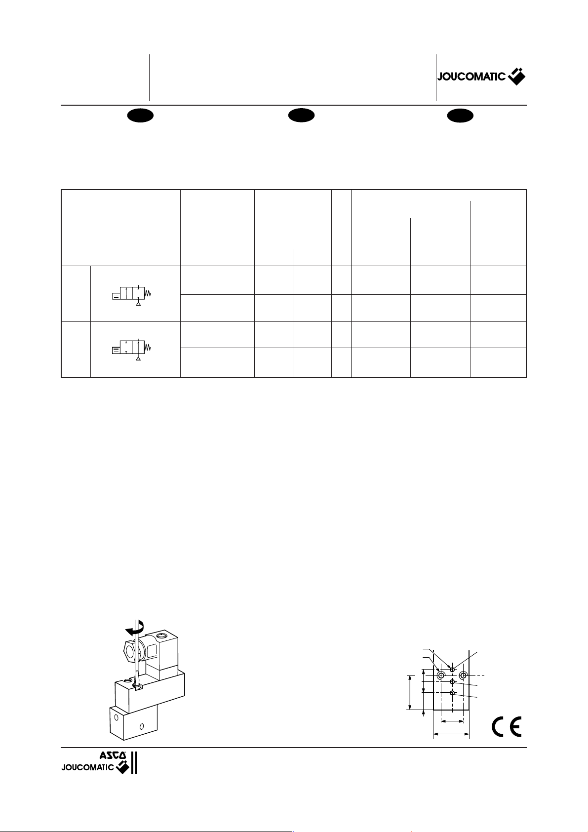
Observe the maximum tightening torque given
below for the 2 mounting screws (see fig. 1).
The equipment may be mounted in any
position.
PNEUMATICAL CONNECTION
The pneumatical connection of the valves
is made on single or joinable subbases.
These subbases are compatible with
CNOMO E06.36.120N.
Make sure that the pressure (1) and outlet
(2) ports are connected.
The compressed air must be filtered at
5 µm without condensate. Install the filter
as close to the piezo valve as possible.
Prevent sealing compound from the
max. : 25 Ncm
2. INSTALLATION / RACCORDEMENT
Les électrovannes sont conçues pour les
domaines de fonctionnement indiqués cidessus et au chapitre 5. Avant de procéder
au montage, dépressuriser les
canalisations.
Respecter le couple de serrage maxi des
2 vis de fixation tel que défini (voir fig.1).
Le produit peut être monté dans n’importe
quelle position.
RACCORDEMENT PNEUMATIQUE
Le raccordement des vannes s’éffectue
par embases simples ou juxtaposables.
Ces embases sont compatibles avec le
plan de pose CNOMO E06.36.120N.
Veiller au bon raccordement des orifices
de pression (1) et de l’utilisation (2).
L’air comprimé doit être filtré à 5 µm sans
condensat. Installer le filtre aussi près que
possible des vannes piézo.
Veiller à ce que la pâte d'étanchéité utilisée
pour les raccords ne pénètre pas dans la
vanne.
connections entering the
valve.
MOUNTING FACE
PLAN DE POSE
AUFFLANSCHBILD
CNOMO E06.36.120N
2. EINBAU / ANSCHLUSS
Verwendung nur innerhalb der oben und in
Abschnitt 5 angegebenen pneumatischen
und elektrischen Daten. Vor dem Einbau
der Ventile Druckleitungssystem drucklos
machen. Das unten angegebene maximale Drehmoment für die beiden Befestigungsschrauben ist zu beachten (siehe
Abb. 1).
Die Einbaulage ist beliebig.
PNEUMATISCHER ANSCHLUSS
Der Anschluß der Ventile erfolgt über Einfach- oder Mehrfachgrundplatten. Das
Flanschbild ist entsprechend CNOMO
E06.36.120N ausgeführt.
Druckeingang (1) und Druckausgang (2)
beachten.
Die Druckluft ist mit 5 µm ohne Kondensat
zu filtern. Filter in der Nähe der Piezoventile
plazieren.
Dichtungsmaterial aus den Anschlüssen
darf auf keinen Fall in das Ventilinnere
gelangen.
3 x Ø 1,5
2 x M3
3,8
3,86,3
11,5
3
2
1
9,7
==
fig.2fig.1
=15=
(383 44 96)
MS-P310.R1
Page 2

Series - Série - Baureihe 630
GB
ELECTRICAL CONNECTION
The electrical connection is only to be
made by qualified personnel in accordance
with the standards and regulations in force.
Turn off all electrical power supply before
starting to work. Tighten all electrical screw
terminals properly. Use a cable with an
appropriate diameter for the PG 7P cable
gland and tighten it properly to ensure
protection degree IP65.
An electrical protection with a reset diode
or varistor is not necessary.
PROPORTIONAL PIEZOTRONIC
Version with pins
Version à broches
Version mit Pins
2 : GND (-) Masse
without
function/
sans fonction/
ohne Funktion
1 : 0-40V DC (+)
FR
RACCORDEMENT ELECTRIQUE
Le raccordement électrique doit être
réalisé par un personnel qualifié et selon
les normes et règlements en vigueur. Avant
toute intervention, couper l’alimentation
électrique. Bien serrer toutes les bornes à
vis. Choisir un câble de diamètre approprié
pour le presse-étoupe PG 7P et veiller à le
serrer correctement pour assurer le degré
de protection IP 65.
Il n’est pas nécessaire de prévoir une
protection électrique par diode de remise
à zéro ou varistor.
PIEZOTRONIC PROPORTIONNELLE PROPORTIONAL-PIEZOTRONIC
Version with wires
Version à sortie de fils
Version mit Litzen
••
• red/rouge/rot AWG 28 : +
••
••
• black/noir/schwarz AWG 28 : -
••
ELEKTRISCHER ANSCHLUSS
Der elektrische Anschluß ist von Fachpersonal entsprechend den geltenden gesetzlichen Bestimmungen auszuführen. Vor
Beginn der Arbeiten alle elektrischen Anschlüsse spannungsfrei schalten. Alle Anschlußklemmen anziehen. Für die PG 7PVerschraubung ein Kabel mit geeignetem
Durchmesser auswählen und festziehen,
um die Schutzart IP65 zu erreichen.
Eine Beschaltung mit Löschdiode oder
Varistor ist nicht notwendig.
••
• A piezo valve has polarization. The
••
piezo element will be damaged if the
polarity of the connections is inversed.
••
• Vanne polarisée. Toute inversion de
••
polarité entraîne la destruction du
produit.
••
• Ventil mit Polarität. Jede Umkehr der
••
Polarität führt zu einer Zerstörung des
Produkts.
DE
!
ELECTRICAL CONTROL
Supply voltage: 0 to 40 V DC
Maximum ripple: 10 %
In order to avoid damaging the valve, the
current must be limited by a serial
protective resistor of 30 ohms at
minimum. Since the proportional valve
does not have reverse voltage protection,
please check for correct polarity as
indicated above.
Physically, there is a hysteresis of approx.
15 % for the flow.
The charging and discharging function
most be done by the user's control system
(see below).
COMMANDE ELECTRIQUE
Tension d'alimentation: 0 à 40 V CC
Taux d'ondulation maxi: 10 %
Afin d’éviter toute détérioration de la vanne,
monter une résistance protectrice de
30 ohms au minimum placée en série
pour limiter le courant. La vanne
proportionnelle n’ayant pas de protection
de polarisation, veillez à respecter la
polarité définie ci-dessus.
Physiquement, l'hystéresis pour le débit
est d'environ 15 %.
Les fonctions de charge et décharge sont
à effectuer par le système de commande
de l'utilisateur (voir ci-dessous).
Min. protective resistance: 30 ohms
Résistance de protection mini.: 30 ohms
Min. Schutzwiderstand: 30 Ohm
ELEKTRISCHE ANSTEUERUNG
Versorgungsspannung: 0 bis 40 V DC
Max. Welligkeit: 10 %
Zur Strombegrenzung muß ein Schutz-
widerstand von mindestens 30 Ohm vorgeschaltet werden. Da beim Proportional-
ventil kein Verpolschutz vorgesehen ist,
unbedingt beim Anschluß auf die o.a. Polarität achten. Bei Nichtbeachtung kann
das Ventil zerstört werden.
Physikalisch bedingt ergibt sich für den
Durchfluß eine Hysterese von ca. 15 %.
Die Lade- und Entladefunktion muß durch
die kundenseitige Ansteuerung übernommen werden (siehe unten).
Empfohlene Ansteuerung
Hysteresis / Hystéresis / HystereseRecommended Control / Commande recommandée /
MS-P310-2
Page 3

Series - Série - Baureihe 630
GB
3. PUTTING INTO SERVICE
A piezo valve differs on principle from a
solenoid valve. Note in particular its low
power consumption and the different flow
of the current.
4. MAINTENANCE
A piezo valve is maintenance-free. Due to
its construction, there is practically no
wear and a very low particle emission. If a
problem occurs during installation,
maintenance or service, please contact
ASCO/JOUCOMATIC or their representatives.
This product complies with the essential
requirements of directives 89/392/EEC
(directive on machines) and 89/336/EEC
(directive on electromagnetic compatibility). A separate Declaration of
Conformity is available on request. Please
provide acknowledgement number and
the reference or ordering code of the
respective product.
5. SPECIFICATIONS
Fluid: air, neutral gas, filtered at 5 µm, free
of condensate, dew point: - 10°C
Max. allowable pressure: 8 bar
Fluid temperature: 0, +60°C
Ambient temperature: 0, +60°C
Service life: > 10
Mounting: on M5 subbases
6. CONSTRUCTION
Proportionally operated valve
Body: synthetic material (PPS)
Sealings : nitrile (NBR)
Internal parts: piezo ceramics
Manual override: impulse type
Mounting position: any
Subbase: brass
7. DIMENSIONS AND WEIGHTS
PIEZO VALVE ALONE, weight: 24 g
9
cycles
FR
3. MISE EN SERVICE
Une vanne piézo se distingue par principe
d’une vanne à commande électromagnétique. Il faut particulièrement noter
la consommation très faible et le passage
du courant tout à fait différent.
4. MAINTENANCE
La vanne piézo ne nécessite aucun
entretien. En raison de sa construction, il
n’y a pratiquement pas d’usure et
l’émission de particules est très faible. En
cas de problème lors du montage, de
l’entretien ou du service, veuillez contacter
ASCO/JOUCOMATIC ou ses représentants.
Ce produit est conforme aux exigences
essentielles des directives 89/392/CEE
(directive machines) et 89/336/CEE
(directive sur la compatibilité électromagnétique). Une Déclaration de
Conformité peut être fournie sur demande.
Veuillez nous indiquer le numéro d'accusé
de réception (AR) et les références ou
codes du produit concerné.
5. SPECIFICATIONS
Fluide: air ou gaz neutre, filtré 5 µm, sans
condensat, point de rosée: -10°C
Pression maxi admissible: 8 bar
Température du fluide: 0, +60°C
Température ambiante: 0, +60°C
Endurance: > 10
Raccordement: par embase M5
6. CONSTRUCTION
Vanne à commande proportionnelle
Corps: matière synthétique (PPS)
Joints d'étanchéité: nitrile (NBR)
Pièces internes: céramique piézo
Commande manuelle: à impulsion
Position de montage: indifférente
Embase: laiton
7. ENCOMBREMENTS ET MASSES
PIEZO-VANNE SEULE, masse: 24 g
9
cycles
DE
3. INBETRIEBNAHME
Piezoventile unterscheiden sich prinzipiell
von Magnetventilen. Dabei ist insbesondere die niedrige Stromaufnahme und der
andersartige Stromverlauf zu beachten.
4. WARTUNG
Piezoventile sind generell wartungsfrei.
Konstruktionsbedingt ergibt sich ein sehr
niedriger Verschleiß und damit verbunden
eine geringe Partikelemission. Bei Schwierigkeiten beim Einbau, Wartung, Betrieb
ist mit ASCO/JOUCOMATIC oder seinen
Repräsentanten Rücksprache zu halten.
Das Produkt erfüllt die wesentlichen Anforderungen der EU-Richtlinien 89/392/EWG
(Maschinenrichtlinie) und 89/336/EWG
(EMV-Richtlinie). Eine separate
Konformitätserklärung ist auf Anfrage erhältlich. Geben Sie bitte für das Produkt
die Nummer der Auftragsbestätigung und
die Bezeichnung oder den Bestell-Code
an.
5. TECHNISCHE DATEN
Medum: Luft, neutrale Gase, gefiltert 5 µm,
kondensatfrei, Taupunkt: -10 °C
Max. zul. Druck: 8 bar
Mediumtemperatur: 0 bis 60 °C
Umgebungstemperatur: 0 bis 60 °C
Lebensdauer: > 109 Schaltspiele
Anschluß: über Grundplatte M5
6. KONSTRUKTIONSMERKMALE
Proportional gesteuertes Ventil
Gehäuse: Kunststoff (PPS)
Abdichtung: Perbunan (NBR)
Innenteile: Piezokeramik
Handhilfsbetätigung: Impuls
Einbaulage: beliebig
Grundplatte: Messing
7. ABMESSUNGEN UND GEWICHTE
PIEZOVENTIL ALLEIN, Gewicht: 24 g
Connector size 15 rotatable by 90°
1
CM6 (Pg 7P)
Manual override by impulse
2
Connecteur taille 15 orientable de
1
90° en 90° CM6 (Pg 7P)
Commande manuelle à impulsion
2
Stecker Größe 15 um 90° umsetzbar
1
CM6 (Pg 7P)
Impulsbetätigte Handhilfsbetätigung
2
MS-P310-3
Subject to change without notice. / Sous réserve de modification sans avis préalable. / Änderungen vorbehalten.
Page 4

Series - Série - Baureihe 630
MS-P310-4
 Loading...