


P
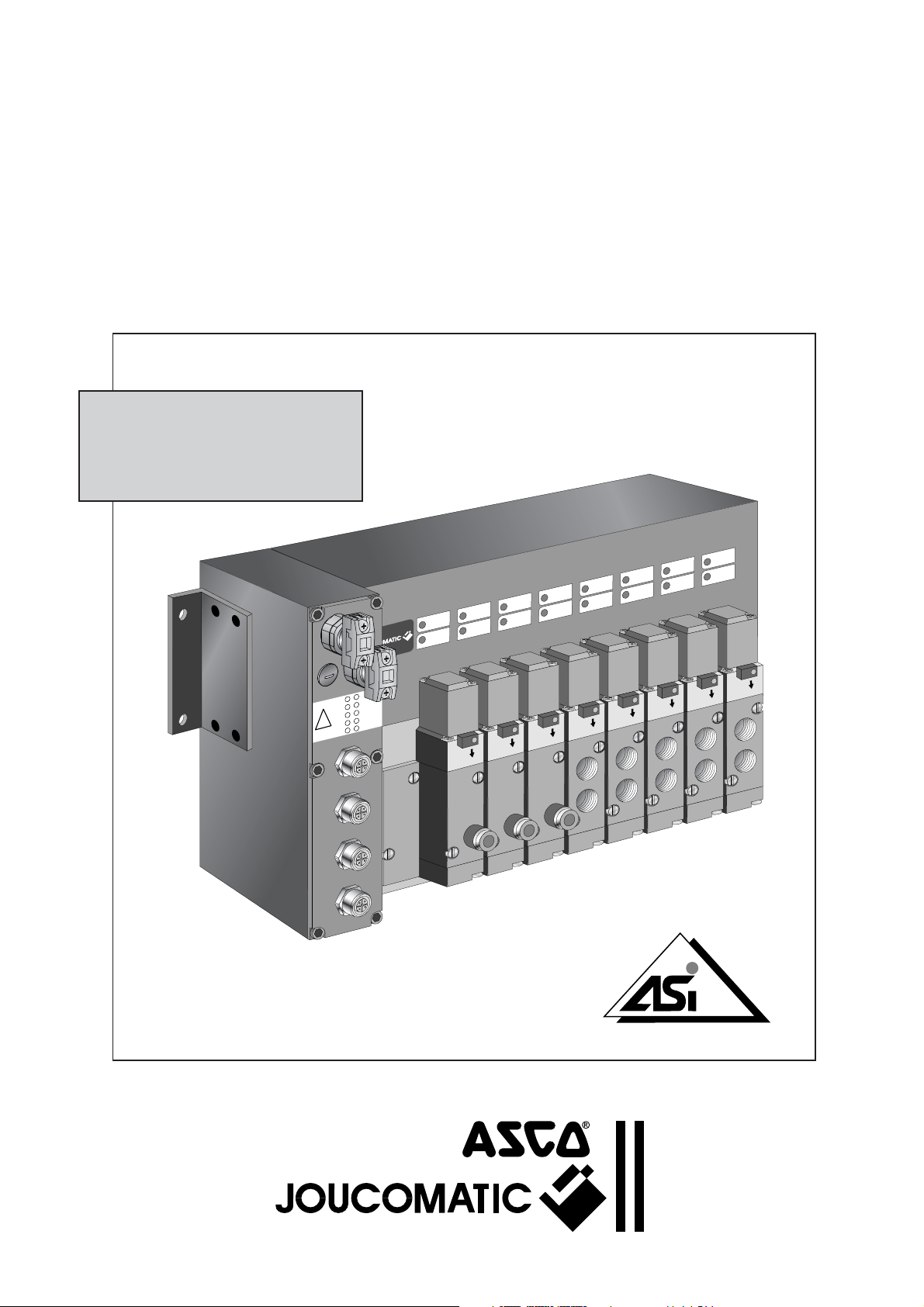
NEUMATIC SPOOL VALVE ISLANDS
ØM5 - G1/8 - G1/4 or instant fittings
designed for connection to a PLC by field bus and
AS-Interface protocol
BUSLINK-Generation C
Installation manual
R
W
P
I
S
A
-2
1
IN
-1
1
-4
1
IN
IN
-3
1
-2
2
IN
IN
-1
2
-4
2
IN
IN
-3
2
IN
5
1
3
NTERFACE
N˚ 21401
MS-P586-5.GB.R2a

BUSLINK - AS-Interface INSTALLATION
CONTENTS Page
1. The BUSLINK system - Generation C - with AS-Interface protocol _________________________________ 3
2. System components _______________________________________________________________________ 5
2.1 Functional description ______________________________________________________________ 5
2.2 Component assembly _______________________________________________________________ 5
2.3 Dimensions - Mounting ______________________________________________________________ 6
2.4 Ordering information for a BUSLINK valve island - Generation C - with AS-Interface ______________ 7
2.5 Manual override ___________________________________________________________________ 8
2.6 Spool valves series 569 - 570 - 571 ____________________________________________________ 9
3. Assembly of BUSLINK Generation C with AS-Interface __________________________________________ 10
3.1 Mounting _________________________________________________________________________ 10
3.2 Pneumatic connection ______________________________________________________________ 10
4. Electrical connection ______________________________________________________________________ 12
4.1 General __________________________________________________________________________ 12
4.2 Voltage supply ____________________________________________________________________ 12
4.3 Calculation of power draw ___________________________________________________________ 12
4.4 Connection of inputs ________________________________________________________________ 13
4.5 Addressing of inputs/outputs _________________________________________________________ 14
4.6 Control signals ____________________________________________________________________ 16
5. AS-Interface network ______________________________________________________________________ 18
5.1 Connection of AS-Interface bus (yellow cable) ___________________________________________ 18
5.2 Programming instructions ____________________________________________________________ 18
5.3 Connection of supply voltage (black cable) ______________________________________________ 19
5.4 Startup of AS-Interface network _______________________________________________________ 19
5.5 Diagnostics _______________________________________________________________________ 19
5.6 Fuses ___________________________________________________________________________ 19
5.7 Accessories for AS-Interface _________________________________________________________ 20
5.8 Dimensions of the accessories for AS-Interface __________________________________________ 20
CAUTION
To avoid malfunction of the bus system, please check on any valve island
• for correct addressing parameters.
• all installation, adjustment and maintenance operations must be carried out by qualified personnel.
A separate Declaration of Incorporation relating to EEC-Directive 89/392/EEC Annex II B is available on request.
Please provide acknowledgement number and serial numbers of products concerned.
This product complies with the essential requirements of the EMC-Directive 89/336/EEC and amendments. A
separate Declaration of Conformity is available on request.
NOTICE
The information in this manual is subject to change without notice.
In no event shall ASCO/JOUCOMATIC be liable for technical or editorial errors or omissions. Neither is any liability assumed
for accidental or consequential damages arising out of or in connection with the supply or use of the informaton contained
herein.
THIS MANUAL CONTAINS INFORMATION PROTECTED BY COPYRIGHT. NO PART OF THIS DOCUMENT MAY BE
PHOTOCOPIED OR REPRODUCED IN ANY FORM OR MANNER WHATSOEVER WITHOUT PRIOR WRITTEN PERMISSION
FROM JOUCOMATIC.
COPYRIGHT © 1999 - 2000 - ASCO/JOUCOMATIC - All rights reserved.
2

INSTALLATION BUSLINK - AS-Interface
42
513
14
12
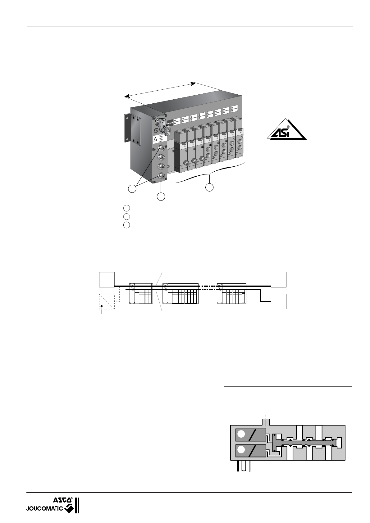
1. The BUSLINK system - generation C - with AS-Interface protocol
Pneumatic islands of 4 to 8 monostable or bistable spool valves, ØM5 - G1/8 - G1/4, with integrated connections for data
exchange with a control system (PLC) by means of a field bus and standardized AS-Interface protocol.
Max. 8 outputs (valves)
R
W
P
I
S
A
-2
1
IN
1
1-
-4
1
IN
IN
-3
1
-2
2
IN
IN
-1
2
-4
2
IN
IN
-3
2
IN
5
1
3
N˚ 21401
NTERFACE
3
1
2
1
Spool valves ( 8 monostable or 4 bistable valves at maximum )
2
Module for AS-Interface connection
3
4 or 8 inputs at option
NOTE - No additional input or output modules available
CONNECTION DIAGRAM
AS-Interface
master
ASi
yellow cable
black cable
AS-Interface bridge to
other protocols
(Profibus-DP, FIPIO,
Device NET, . . .)
ADVANTAGES
With the many advantages it offers, the Buslink system meets modern needs for automated installations.
• No bulky and difficult wiring.
• Time and money saved due to direct electric cabling and common air supply.
• Unit tested and equipped with spool valves at delivery.
• Easy maintenance.
COMBINATIONS
Buslink units can be grouped as follows:
•
Islands of 4, 6 or 8 monostable 3/2, 5/2 or 5/3 spool valves or 4 bistable spool
valves or 4 double 3/2 NC.
•
Differently sized islands for spool valve series 569 - 570 - 571 (only one valve
size per island
• Upon request, each island can be equipped with four 5-pin female panel
connectors M12 to connect 4 inputs (1 node configuration) or 8 outputs (2
node configuration).
• Monostable and bistable spool valves with integrated push/pull pilot valves
(
), all functions available on one island.
*
• Any configuration possible upon request.
).
(*) Bistable spool valves series 569 - 570 - 571
integrated push/pull pilot valves (pilots placed on
one side of the island offering a compact solution).
AS-Interface
supply
24V =
with
3

BUSLINK - AS-Interface INSTALLATION
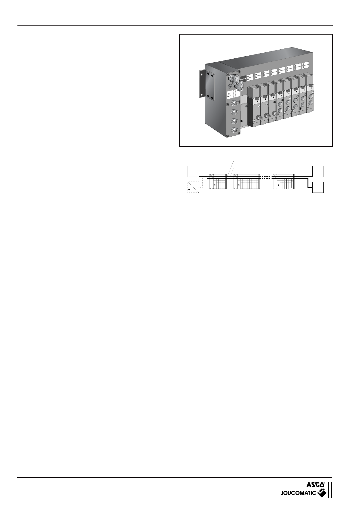
AS-INTERFACE (AS-Interface)
Pneumatic spool valve island for data exchange via field bus
and standardized AS-Interface protocol.
The connection between a control system (PLC) and several spool
valve islands by means of a field bus allows the transmission of data
with a standard AS-Interface cable :
• control signals to the spool valves,
• information signals from the sensor inputs.
ADVANTAGES
With the many advantages it offers, the Buslink system meets
modern needs for automated installations.
• No bulky and difficult wiring.
• Time and money saved due to direct electric cabling and common
air supply.
• Visual display and quick disconnection for easy maintenance.
• Unit tested and equipped with spool valves at delivery.
R
W
P
I
S
A
-2
1
IN
-1
1
-4
1
IN
IN
-3
1
-2
2
IN
IN
-1
2
-4
2
IN
IN
-3
2
IN
5
1
3
COMBINATIONS
Buslink units can be grouped as follows:
• Modules for 3/2, 2x3/2, 5/2 or 5/3 spool valves series 569 (ØM5 or
AS-Interface
master
yellow cable
black cable
instant fittings) - 570 (G1/8 or instant fittings) - 571 (G1/4).
ASi
OPTIONS
• Island with air supplied at two different pressure rates.
• Island with external air supply for pilot pressure.
AS-Interface bridge to other protocols
(Profibus-DP, FIPIO, Device NET etc.)
COMMUNICATION CHARACTERISTICS
Communication protocol : AS-Interface (bidirectional mode)
Transmission : flat AS-Interface cable (yellow, 2 wires)
Bus structure : any structure according to AS-Interface standards
Max. number of spool valve islands : 31 nodes (1 valve island can have 2 nodes)
Number of valves per island : 4 to 8
Number of inputs/outputs : 0, 4 or 8 inputs
Max. bus cable length : 100 m (300 m with repeaters)
Island addressing (participants) : AS-Interface master
Compatibility with control system : no modification of current programmes
Compatible equipment : various options
ELECTRICAL CHARACTERISTICS
Supply voltage : 24 V DC, ±10% at the island.
Supply to the valves with an additional flat AS-Interface cable (black, 2 wires).
Max. ripple ratio : 10 %
Consumption : 79 mA per valve and 9 mA per input
Coil insulation class : F
Protection : IP65
Electrical insulation of the inputs : optocouplers
Peak voltage suppression : integrated in the island for each coil
Additional 24 V supply connection : vampire-type panel connector for AS-Interface cable (black cable)
Bus connection (IN/OUT) : vampire-type panel connector for AS-Interface cable (yellow cable)
Input connection : 5-pin female panel connector M12
Earth connection : earthing screw on the pneumatic subbase
Electromagnetic compatibility : in accordance with the EU directive EMC 89/336/EEC
CE identification
AS-Interface
supply
24V =
PNEUMATIC CHARACTERISTICS
Fluid : air or neutral gas, filtered at 30 µm, lubricated or not
Operating pressure : 1.5 to 8 bar (2.5 to 8 bar with 3/2 NO spool valves and series 569 functions 5/3)
Flow rate (Qv at 6 bar) series 569 : 175 l/min
series 570 : 600 l/min (3/2: 400 l/min - 2x3/2 : 550 l/min)
series 571 : 1050 l/min
Allowable temperature : +5 °C to +50 °C
ACCESSORIES: see following page
4
INSTALLATION BUSLINK - AS-Interface
2. SYSTEM COMPONENTS
2.1 FUNCTIONAL DESCRIPTION
The spool valve islands are connected to a PLC with a (yellow) AS-Interface bus cable to pilot the spool valves and detect the sensor
status if the island is provided with inputs. A second adapter is used to supply the valves with power (black cable).
The pressure supply and exhaust are collected in the pneumatic subbase. The spool valves ensure the pressure supply and exhaust
of the pneumatic actuators. The pneumatic connection of the actuators is made on the top side of the spool valves. The island can be
equipped with inputs upon request. The electrical sensors are connected to the input modules with male connectors ØM12.
MAXIMUM CAPACITY OF THE SPOOL VALVE ISLAND
According to the configuration you choose, the islands can be equipped with a maximum of 8 inputs and 8 outputs (1 output = 1 spool
valve pilot).
The maximum capacity of the island depends on the number of nodes (see table below).
Example for maximum configuration:
Number
of nodes
1
2
Max. number
of valves
4 monostable
or 2 bistable
or 2 double 3/2 NC
8 monostable
or 4 bistable
or 4 double 3/2 NC
or 4 monostable +
2 bistable (1)
Max. number
of inputs
4
8
NOTE:
- Maximum configuration for 1 node
: 4 outputs / 4 inputs
- Maximum configuration for 2 nodes: 8 outputs / 8 inputs
- 1 output = 1 monostable spool valve
- 2 outputs = 2 monostable spool valves or 1 bistable spool
valve
(1) In this configuration, the bistable spool valves are
always to be placed on the right-hand side of the island.
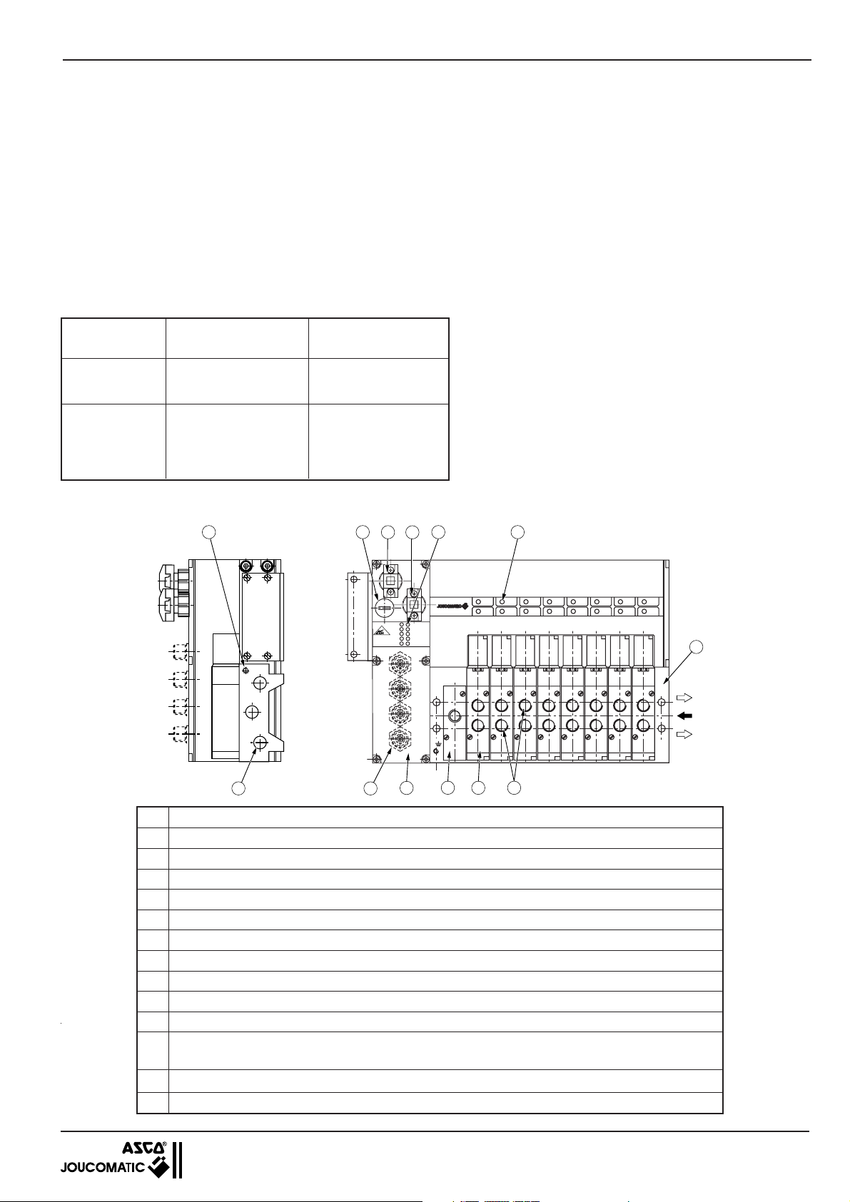
2.2 COMPONENT ASSEMBLY
13
5
No. Description
1 Subbase for pneumatic connection of the Buslink valve island
2 AS-Interface bus connection
3 Monostable or bistable 3/2-2x3/2-5/2-5/3 spool valves (max. 8)
4 Operating ports "2-4" with threaded connection or instant fittings (top side ports)
5 Pressure supply "1" and exhausts "3-5" with threaded connections
6 Connecting flange for pressure supply (for island with 8 valves) (see page 11)
7 LED visual indicator for pilot valves
8 AS-Interface; adapter for AS-Interface bus cable (yellow)
9 AS-Interface; adapter for additional AS-Interface power supply cable (black)
10 Island addressing
2 LEDs for AS-Interface and supply
11
8 LEDs for inputs
12 Input connection with female panel connectors ØM12 (upon request)
13 Common exhaust of pilots 82-84 (ØM5)
10 11
8
9
PWR
ASI
IN1-1 IN1-2
NTERFACE
IN1-3 IN1-4
IN2-1
IN2-2
IN2-3 IN2-4
2
12
7
1
5
1
3
6
3 4
5

BUSLINK - AS-Interface INSTALLATION
2.3 DIMENSIONS - MOUNTING
The island is provided with four mounting holes in the
spool valve subbase and two mounting holes on the
left side for input/output modules. The centre distance
L2 is dependent on the number and size of the spool
valves.
Total length of spool valve island: L2 + 77
Make sure to provide for enough room on the right
side for pressure supply and optional exhaust
silencers.
P1
2 Ø5,5
PWR
ASI
IN1-1 IN1-2
NTERFACE
IN1-3 IN1-4
IN2-1
IN2-2
IN2-3 IN2-4
n2
P3 (1) (2)
P2K2
B
Valve
series
569 (M5)
570 (G1/8)
571 (G1/4)
CK1D
28,5
5 5,5
66,5 L2
L2
n2: number of valves
B C D ØF K1 K2 4 6 8 P1 P2 (1) (2)
163 23 47.5 4.5 60.4 15 91.5 123.5 155.5 3 35 120
163.5 28.3 59 5.5 60.4 21 105 143 181 3 33 130 190
181.5 34.7 70.5 5.5 60.4 26 126.5 172.5 218.5 3 31 170
C
4 ØF
P3
mm
(1) BUSLINK AS-Interface without input : height required for pneumatic cabling with rilsan hoses (the AS-Interface cables are
connected horizontally).
(2) BUSLINK AS-Interface with inputs : height required for electric connection with M12 connectors and cables.
WEIGHTS
Weight of a Buslink island without bus module (kg)
Valve
series
n2: number of valves
468
Weight of one bus module
- without input : 0.550 kg
- with inputs : 0.600 kg
569
570 (3/2)
570 (5/2-5/3)
571
0.9 1.32 1.73
1.14 1.6 2.06
1.18 1.66 2.14
1.61 2.31 3.01
Total weight of a BUSLINK spool valve island - generation C: define the weight of the pneumatic components from the spool valve series
and number of valves required (see above table) + the weight of the bus connection module (with or without inputs).
6

INSTALLATION BUSLINK - AS-Interface
24
3
5
14
12
1
24
3
5
14
12
1
24
3
5
14
12
1
2.4
ORDERING INFORMATION FOR A BUSLINK VALVE ISLAND - GENERATION C - WITH AS-Interface
When ordering please specify the electrical compontents (1), the pneumatic components (2), and the optional accessories
separately.
1
■■
■
Electrical components
■■
Generation C
E Electrical components
BI BUSLINK-AS-Interface
OPTION
00 without option
- -
other options
}
99
Input/Output number
A1 1 node - 4 outputs
A2 1 node - 4 outputs / 4 inputs
A3 2 node - 8 outputs
A4 2 node - 8 outputs / 8 inputs
2
■■
■
Pneumatic components
■■
Generation C
P Pneumatic components
GR
2 569 (ØM5 or instant fittings)
3 570 (G1/8 or instant fittings)
4 571 (G1/4)
Spool valve
series and size
OPTIONS
00 without
- -
other options
}
99
Connection
G Gaz thread
N NPT thread
Q instant fittings (metric)
Ports : 2 - 4
Position
0 top side
Connection
G Gaz thread
N NPT thread
Position
Ports: 1 - 3 - 5
1 lateral
▲
TYPE
C
▼
B
E
▼
▲
GR
OPTION
C
P
▲
▲
▲
OPTION
I
▲▲▲
▲
▼
-
▼
An island can be equipped with two or
four M12 connectors (A) for connection of
four or eight input/sensors as shown in
the table opposite.
No. of
places
1234 5678
-
▲
Number of positions : - 4 bistable valves or
Type
Blanking plates for electr./pneum. mounting surface
A
Z
2
3
1
K
2
4
141214
M
J
5
3
1
2
4
14 1214
5
3
1
G
B
E
4
- 4 to 8 monostable valves (1)
Spool valve functions
3/2 NC- Solenoid air operated pilot
2 x 3/2 NC
5/2 - Solenoid air operated pilot
5/2 - Solenoid air operated
5/3 - Pressure held (W1)
5/3 - Pressure applied (W2)
5/3 - Exhaust released (W3)
R
PW
SI
A
-2
1
IN
1-1
-4
1
IN
IN
-3
1
-2
2
IN
N
I
2-1
-4
2
IN
IN
3
2IN
A
6
8
Spring/Differential return
Solenoid air operated pilot
Differential return
Differential return
pilot and return
Solenoid air operated pilot
Solenoid air operated pilot
Solenoid air operated pilot
04
Number of spool valve
06
08
places
on the island
(1)
(1) For detailed information on spool valves see chapter 2.1.
ORDERING EXAMPLE:
Reference : CEBI00A4
CP300Q0G106-KKMMJJ
BUSLINK valve island - Generation C, AS-Interface protocol, with 2 nodes, 8 outputs and 8 inputs over 4 ØM12 connectors.Island for 6 spool
valves series 570 with outputs and instant fitting for flexible hose OD 6 mm,
equipped as follows:
- Positions nos. 1 and 2 : 2 monostable 3/2 spool valves NC, type K
- Positions nos. 3 and 4 : 2 monostable 5/2 spool valves, type M
- Positions nos. 5 and 6 : 2 bistable 5/2 spool valves, type J
NOTE : In this configuration, the bistable spool valves are always to be placed on the right-hand side of the island.
ACCESSORIES (see page 20)
7

BUSLINK - AS-Interface INSTALLATION
2.5 MANUAL OVERRIDE
Spool valves series 569 - 570 - 571 are equipped with manual
override by impulse (A).
monostable spool valve bistable spool valve
(A)
Valve type
(A)
Procedure Valve function
3/2 - 5/2
monostable
(A)
(bistable spool valve)
14
12
The valve is activated as long as the manual override is
pressed in (
Reset when the manual override is released
)
*
42
513
5/2
bistable
or
5/3
with neutral position
5/2
5/3
5/2
5/3
5/2
5/3
5/2
5/3
The valve is activated (
Permanently activated position is maintained
Reset to central neutral position
Reset (*) (identical to return 12)
Reset position is maintained
Reset to central neutral position
) (identical to pilot 14)
*
) These changes can only be made if the valve is under pressure.
(
*
Supply pressure at port 1 (min. 1.5 bar).
8

INSTALLATION BUSLINK - AS-Interface
2.6
SPOOL VALVE SERIES 569 (ØM5) - 570 (G1/8) - 571 (G1/4)
SPECIFICATIONS
FLUID : air or neutral gas, filtered 30µm, lubricated or not
OPERATING PRESSURE : 1.5 to 8 bar (2.5 to 8 bar series 569 functions 5/3)
ALLOWABLE TEMPERATURE : +5 °C to +50 °C
FUNCTION : 3/2 - 2x3/2 - 5/2 - 5/3, monostable or bistable
OPERATORS : solenoid air operated with internal supply
SPECIAL FEATURE : in the push/pull version both pilots are integrated in
the operator placed on one side = compact solution
(see P586-2).
CONSTRUCTION
SPOOL VALVE
Body in light alloy, cover in thermoplastic (PA-Ar)
Internal parts in stainless steel, light alloy and acetal resin (POM)
Sealings in nitrile (NBR)
PILOT VALVE
Sealings in nitrile (NBR)
Electrical equipment in compliance with standard NF C79300
Coil and iron circuit encapsulated in epoxy resin
Impulse manual override (A)
ELECTRICAL SPECIFICATIONS
VOLTAGE : 24V DC ±10%
max. ripple ratio: 10%
CONSUMPTION : 1.7 W (per coil)
INSULATION CLASS : F
PROTECTION : IP 65
Monostable
spool valve
(A)
Bistable
spool valve
(A)
1 = Pressure 12 = Return
2-4 = Operating ports 14 = Pilot
3-5 = Exhausts
570 spool valve (2 x 3/2)
570 spool valve (5/2)
CHOICE OF EQUIPMENT
(1)
2
TYPE
Symbols
Functions
3/2
Z
NC
1
2x
3/2
K
M
J
G
B
E
NC
5/2
5/2
14
5/3
14
5/3
14
5/3
4
141214
5
1
4
14 1214
5
1
24
5
3
1
24
5
3
1
24
5
3
1
Operators
Pilot
(14)
Solenoid
3
2
3
2
3
12
12
12
air
Solenoid
air
Solenoid
air
Solenoid
air
Pressure held
solenoid air
Pressure applied
solenoid air
Exhaust released
solenoid air
Return
(12)
Spring/
Differential
Differential
Differential
Solenoid
air
W1
W2
W3
GR
3 (570)
(570)
3
2 (569)
3 (570)
4 (571)
2 (569)
3 (570)
4 (571)
2 (569)
3 (570)
4 (571)
2 (569)
3 (570)
4 (571)
2 (569)
3 (570)
4 (571)
Instant fitting for flexible
Ø
Ports
2 - 4
hose O.D.6 mm
G1/8
G1/8
M5
G1/8
G1/4
M5
G1/8
G1/4
M5
G1/8
G1/4
M5
G1/8
G1/4
M5
G1/8
G1/4
Ori-
fice
(mm)
2,5
2,5
2,5
2,5
2,5
Flow
at 6 bar
(l/min.)
5
5
4
6
4
6
4
6
4
6
400
550
175
600
1050
175
4
6
600
1050
175
600
1050
175
600
1050
175
600
1050
VALVE
CODES
(24 VDC)
570 00 053
570 00 051
570 00 103
569 00 012
570 00 012
571 00 012
569 00 014
570 00 014
571 00 014
569 00 016
570 00 016
571 00 016
569 00 018
570 00 018
571 00 018
569 00 020
570 00 020
571 00 020
The 5/2 spool valves can be used in function 3/2 NC (by plugging port 2) or 3/2 NO (by plugging port 4).
(1) The function of push/pull pilot valves corresponds to the function of conventional valves. Marking to ISO 1219-1.
NOTE - Only one valve size per island.
9

BUSLINK - AS-Interface INSTALLATION
3 ASSEMBLY OF BUSLINK Generation C with AS-Interface
3.1 MOUNTING
Mount the island as described in chapter 2.3.
Make sure to provide for enough room for the cables, connectors and optional exhaust silencers. Proceed with pneumatic and
electrical connection.
A
Pressure supply 1
and exhausts 3 - 5
B
Operating ports 2 - 4
C
Bus connection (yellow cable)
D
24VDC power supply to valves (black cable)
E
Sensor inputs (upon request)
C
C
D
V
4
2
I
S
A
2
N
I
1
1
N
I
4
1
N
I
1
3
N
I
2
1
N
I
2
1
N
I
4
2
N
I
2
3
N
I
2
5
D
1
3
E
3.2 PNEUMATIC CONNECTION
3.2.1 GENERAL
■■
■ To subbase
■■
The lines for the following common pneumatic signals are collected in the subbase: supply pressure (1), exhausts (3) and (5),
exhaust. The connecting ports are either on the right side or - in some versions - on the left side of the subbase (see below).
82-84
5
1
A
3
B
and pilot valve
■■
■ To spool valves
■■
Two connection possibilities for operating ports (2 - 4) on top side:
- Threaded connection directly on the spool valve body.
- With instant fittings for flexible hose (for valve series 569 and 570).
■■
■ Connecting instructions
■■
- Remove all protective plastic caps.
- Insert the gasket which generally comes with the ØM5 connectors or banjo-type screw-fittings.
- Screw down the connectors and screw-fittings correctly.
- Screw in the exhaust silencers.
- Connect the pneumatic piping. Gather the tubes in order to have neat and accessible piping.
■ Recommendation for pressure supply connection (see following page)
■ Connections
Series
Pressure supply
Exhausts
Pilot valve exhausts
Operating ports
(82/84)
(1)
(3) (5)
(2) (4)
569 G 1/8 G 1/8 M 5 M 5 (❇)
570 (3/2-2x3/2) G 1/4 G 1/4 M 5
instant fittings
G1/8
570 (5/2-5/3) G 1/4 G 1/4 M 5 G 1/8 (❇)
571 G 3/8 G 3/8 M 5 G 1/4
(❇) or with connecting flange and instant fittings for flexible hose:
• OD 4 mm (569)
• OD 6 mm (570)
Version with threaded connection Version with instant fitting
10
2
4
2
4

INSTALLATION BUSLINK - AS-Interface
3.2.2 CONNECTION OF PNEUMATIC SUPPLY
■ SUPPLY WITH 1 PRESSURE (P1)
- Island with 4 to 6 spool valves: pressure supply on right side.
PWR
ASI
IN1-1 IN1-2
NTERFACE
IN1-3 IN1-4
IN2-1
IN2-2
IN2-3 IN2-4
+
+
5
P1
1
3
A maximum of five spool valves can be operated at the same time without pneumatic malfunction.
- Island with 8 spool valves
The pressure on an island with more than 6 spool valves must be supplied from both sides.
For this purpose, all islands for 8 to 16 spool valves are equipped with a connecting flange.
PWR
ASI
IN1-1 IN1-2
NTERFACE
IN1-3 IN1-4
IN2-1
IN2-2
IN2-3 IN2-4
5
5
1
P1
1
I
S
A
1
-
1
N
I
3
-
1
N
I
1
-
2
N
I
3I
-
2
N
I
R
W
P
2
-
1
N
I
4
-
1
N
I
2
-
2
N
I
4
-
2
N
5
1
3
3
P1
3
Valve
series
Ports
1 - 3 - 5
569 G1/8
570 G1/4
571 G3/8
P1
■ Supply with 2 different pressures (P1 - P2)
Possibility of supplying 1 to 4 spool valves with pressure P2 (consult us).
■ External pressure supply of pilot valves (consult us)
11

BUSLINK - AS-Interface INSTALLATION
1
3
5
4 ELECTRICAL CONNECTION
4.1 GENERAL
The islands are equipped with 2 vampire-type AS-Interface connectors to connect the bus network and power supply (B).
Upon request, the subbases can also be provided with two or four 5-pin female panel connectors M12 for the inputs (A).
Cables and M12 connectors must be supplied separately.
Integrated protection circuit for each coil.
Grounding
Grounding for personal protection is
V N.N
effected directly on the island with the
ground screw.
Bobine
Coil
Spule
GND
4.2 VOLTAGE SUPPLY
- The yellow cable is used to supply the AS-Interface.
- The black cable is used to supply the valves and inputs.
Supply voltage : 24 VDC, ±10%
Max. ripple ratio : ±10 %
Consumption : 1.7 per coil, + 0.2 W per LED
max. 5 W / bus electronics
Inputs: total value < 0.5 A
Calculation of power draw (see below).
Check the supply voltage during operation and make sure the admissible tolerance (±10%) is observed.
B
R
W
P
ASI
-2
IN1
1-1
1-4
IN
IN
1-3
2-2
IN
IN
2-1
2-4
IN
IN
2-3
IN
A
4.3 CALCULATION OF POWER DRAW
The island's power draw depends on its configuration.
Calculating this power draw will allow the user to provide for optimal 24 V power supply.
Consumption of the different elements:
- Consumption of bus electronics : 40 mA
- Consumption of one input : 9 mA
- Consumption of one valve + LED : 79 mA
12

INSTALLATION BUSLINK - AS-Interface
1
2
4
3
5
+
-
+
-
4.4 CONNECTION OF INPUTS (inputs upon request)
Connection with detachable M12 connectors with protection to IP65.
Possibility of connecting sensors with 2 or 3 wires
Island provided with
two M12 panel connectors
R
W
P
for 4 inputs
I
S
A
2
-
1
N
I
1
-
1
4
-
N
1
I
N
I
3
2
1
-
N
2
I
N
I
1
-
2
4
-
N
I
2
N
I
3
-
2
N
I
(2 inputs for each connector)
Input addressing:
x : IN1-1, IN1-3
X + 1 : IN1-2, IN1-4
(see chapter 4.5)
CONNECTION WITH M12 CONNECTOR
The two following M12 connector types are recommended:
- Straight duo connector (A) for the connection of 2 separate cables (one for each sensor)
- Straight mono connector (B) for the connection of a sensor or cable bundle.
Sensor Sensor Sensor Sensor Sensor
(A) 881 00 253
● Sensors with 2 wires ● Sensors with 3 wires (magnetoresistive example)
24V 24V
(B) 881 00 330
Wiring diagram of inputs
View from screw side of male connector
24V 24V
Island provided with
four M12 panel connectors
R
W
P
for 8 inputs
I
S
A
2
-
1
N
I
1
-
1
4
-
N
1
I
N
I
3
2
1
-
N
2
I
N
I
1
-
2
4
-
N
I
2
N
I
3
-
2
N
I
(2 inputs for each connector)
Input addressing:
x : IN1-1, IN1-3, IN2-1, IN2-3
X + 1: IN1-2, IN1-4, IN2-2, IN2-4
(see chapter 4.5)
Connectors to be supplied separately:
(A) Straight 5-pin male duo connector
M12, cable feed-throughs of 3 to
5 mm dia. for each cable
code: 881 00 253
(B) Straight 5-pin male mono connector
M12 for 1 cable feed-through of 4 to
6 mm dia.
code : 881 00 330
1
Sensor
5
x+1
IN x+1
2
Sensor
x
IN x
IN x+1
GND GND
Sensor
x+1
Sensor x
IN x
4
3
Pin Name Description
1 24V DC Supply of inputs
2 IN x +1 Input: positive logic x + 1
3 0 V Common ground (sensors with 3 wires)
4 IN x Input: positive logic x
5 PE Protection earth
NOTE:
The status of the connected sensors can be sampled over the inputs. The inputs have positive logic, they can be operated together
with sensors with pnp outputs. The inputs are "LOW" and must be switched to + 24 V (HIGH) in order to be activated.
Typical input current: 9 mA at 24 VDC.
● Logical status "LOW" : < 8 V ● Logical status "HIGH" : > 14 V
Max. input voltage for external power supply of inputs: 40 V.
When 2-wires sensors are connected, the max. residual current must be < 1 mA.
In "LOW" status, the max. residual current at the input must be < 1 mA.
13

BUSLINK - AS-Interface INSTALLATION
4.5 ADDRESSING
4.5.1 ADDRESSING OF VALVES
Control signals for the valves (see chapter 4.6)
Valve are addressed according to the type of valve used (monostable or bistable valve).
■ Monostable valves (max. = 8)
Horizontal addressing:
Valve position
12345678
Addressing:
V0.0 V0.2 V0.4 V0.6 V1.0 V1.2 V1.4 V1.6
__ ______
1st node 2nd node
Valve
position
1234
Addressing :
V0.0 V0.2 V0.4 V0.6
V0.1 V0.3 V0.5 V0.7
Pilot signals (14)
Return signals
(12)
1st node 2nd node
ASI
IN1-1 IN1-2
IN1-3 IN1-4
IN2-1
IN2-3 IN2-4
Pilot
signals
PWR
IN2-2
Return
signals
■ Bistable valves (max. = 4)
Addressing priority is from top to bottom and from left to right.
PWR
ASI
IN1-1 IN1-2
IN1-3 IN1-4
IN2-1
IN2-2
IN2-3 IN2-4
4 monostable
valves
2 bistable valves
(2nd node)
(1st node)
4.5.2 INPUT ADDRESSING
■ NOTE: In 2-node configuration it is possible to mix monostable and
bistable valves (max. configuration = 4 monostable valves and 2 bistable
valves). These are always placed as shown opposite.
In this case, the addressing priority is as follows:
Adressing:
AS-Interface island with inputs
PWR
ASI
IN1-1 IN1-2
IN1-3 IN1-4
IN2-1
IN2-2
IN1-1
IN1-3
IN2-1
IN2-3
IN2-3 IN2-4
IN1-2
IN1-4
IN2-2
IN2-4
Valve position
123456
V0.0 V0.2 V0.4 V0.6 V1.0 V1.2
__ __
V1.1 V1.3
1st node 2nd node
1st node
2nd node
Connect 2 sensors (2 inputs) for each M12 connector (see previous page).
14

INSTALLATION BUSLINK - AS-Interface
4.5.3 ADDRESSING SUMMARY
■ AS-Interface island with 1 node
4 monostable valves
(Island reference : A1)
PWR
ASI
IN1-1 IN1-2
NTERFACE
IN1-3 IN1-4
IN2-1
IN2-2
IN2-3 IN2-4
+
234
1
+
4 monostable valves and 4 inputs
(Island reference : A2)
PWR
ASI
IN1-1 IN1-2
NTERFACE
IN1-3 IN1-4
IN2-1
IN2-2
IN2-3 IN2-4
+
234
1
+
Data bit
D0
D1
D2
D3
Valves Inputs
Valve no.1 / 14 Input 1
Valve no. 2 / 14 Input 2
Valve no. 3 / 14 Input 3
Valve no. 4 / 14 Input 4
■ AS-Interface island with 2 nodes
8 monostable valves or 4 bistable valves 8 monostable valves or 4 bistable valves and 8 inputs
(Island reference : A3) (Island reference : A4)
Addressing
V0.0 IN1-1
V0.2 IN1-2
V0.4 IN1-3
V0.6 IN1-4
NTERFACE
ASI
IN1-1 IN1-2
IN1-3 IN1-4
IN2-1
IN2-3 IN2-4
PWR
IN2-2
+
678
234
1
+
5
IN1-1 IN1-2
NTERFACE
IN1-3 IN1-4
IN2-1
IN2-3 IN2-4
PWR
ASI
IN2-2
+
234
1
+
678
5
Valve addressing Input addressing
4 monostable
Node number Data bit 8 monostable
valves
4 bistable
valves
valves
and
4 inputs 8 inputs
2 bistable valves
D0
D1
1
D2
D3
D0
D1
2
D2
D3
Valve X/14 = voltage supply to "pilot" coil 14
Valve 1/14 Valve 1/14 Valve 1/14 Input 1 Input 1
V0.0 V0.0 V0.0 IN1-1 IN1-1
Valve 2/14 Valve 1/12 Valve 2/14 Input 2 Input 2
V0.2 V0.1 V0.2 IN1-2 IN1-2
Valve 3/14 Valve 2/14 Valve 3/14 Input 3 Input 3
V0.4 V0.2 V0.4 IN1-3 IN1-3
Valve 4/14 Valve 2/12 Valve 4/14 Input 4 Input 4
V0.6 V0.3 V0.6 IN1-4 IN1-4
Valve 5/14 Valve 3/14 Valve 5/14
V1.0 V0.4 V1.0 IN2-1
Valve 6/14 Valve 3/12 Valve 5/12
V1.2 V0.5 V1.1 IN2-2
Valve 7/14 Valve 4/14 Valve 6/14
V1.4 V0.6 V1.2 IN2-3
Valve 8/14 Valve 4/12 Valve 6/12
V1.6 V0.7 V1.3 IN2-4
(1)
: port 4 under pressure
_
_
_
_
Input 5
Input 6
Input 7
Input 8
Valve X/12 = voltage supply to "return" coil 12 : port 2 under pressure
(1)Except for monostable 3/2 valves series 570 where the pilot is 12 (port 2 under pressure). Return by cutting supply voltage to coil
12 (for pilot signals see chapter 4.6 and following pages).
15
BUSLINK - AS-Interface INSTALLATION
141214
2
3
5
4
1
1
14 1214
2
3
5
4
1
P
0
P
0
24 V
0 V
24 V
0 V
2
2
W2 (B) W3 (E) W1 (G)
24
3
5
14
12
1
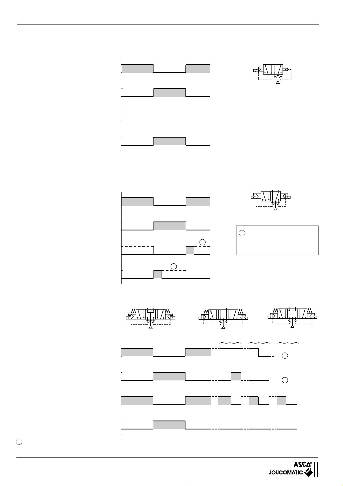
4.6 CONTROL SIGNALS
■ MONOSTABLE 5/2 SPOOL VALVES (differential pneumatic return) - Type: M
Port 2
0
P
P
Port 4
0
24 V
Signal to coil 12
0 V
24 V
Signal to coil 14 (pilot)
0 V
■ BISTABLE 5/2 SPOOL VALVE - Type: J
Port 2
Port 4
Signal to coil 12 (return)
P
0
P
0
24 V
0 V
not necessary (no coil 12, differential return)
1
P = Pressure
These signals can be pulsed
or maintained until change of
status.
Signal to coil 14 (pilot)
24 V
■ 5/3 SPOOL VALVES - Types: B - E - G
Port 2
Port 4
Signal to coil 12
Signal to coil14
1
0 V
14
24
5
1
12
3
24
14
5
1
12
3
2
In the 5/3 pressure held version type W1, the pressure at ports 2 and 4 is that which existed when coils 12 and 14 were deenergized.
16
INSTALLATION BUSLINK - AS-Interface
P
0
P
0
24 V
0 V
24 V
0 V
P
0
P
0
24 V
0 V
24 V
0 V
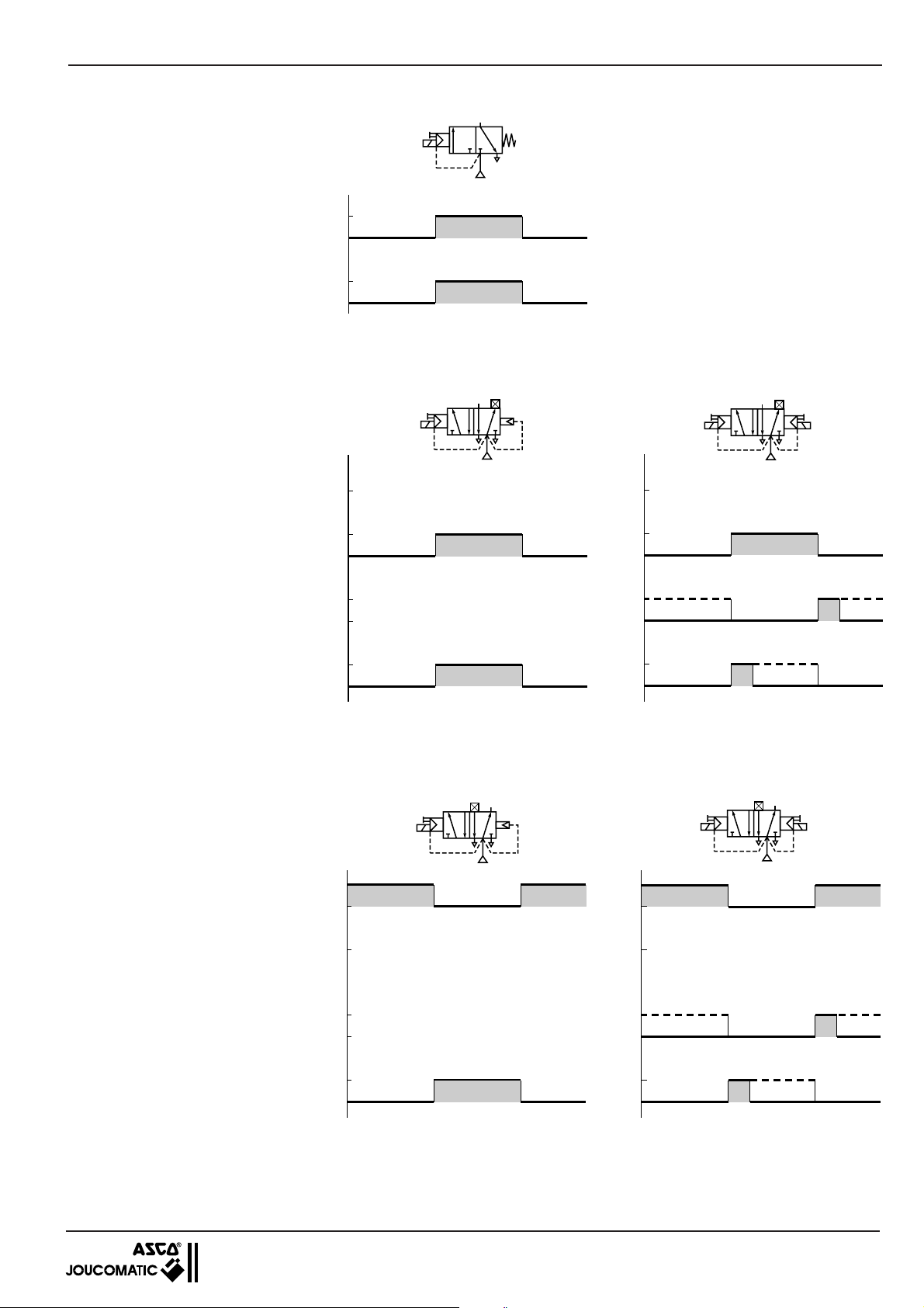
■ MONOSTABLE 3/2 SPOOL VALVE SERIES 570 NC - Type: Z
12
2
3
1
Port 2
P
0
) Take signal 14 for the addressing and
(
*
Coil 12 (
MONOSTABLE OR BISTABLE 5/2 SPOOL VALVE OPERATED IN 3/2 NC FUNCTION (block port 2)
■
)
0 V
*
24 V
pilot connection of the 3/2-spool valves
NC into account.
MONOSTABLE
2
4
Port 2
Blocked
141214
5
3
1
14 1214
Blocked
Port 4
Signal to coil 12
not necessary (differential return)
BISTABLE
4
5
1
2
3
Signal to coil 14
■ MONOSTABLE OR BISTABLE 5/2 SPOOL VALVE OPERATED IN 3/2 NO FUNCTION (block port 4)
MONOSTABLE
2
4
141214
5
3
1
Port 2
P
0
24 V
P
0
Blocked
Port 4
Signal to coil 12 not necessary (differential return)
0 V
Signal to coil 14
24 V
0 V
24 V
0 V
24 V
0 V
P
0
P
0
Blocked
BISTABLE
14 1214
2
4
5
3
1
17

BUSLINK - AS-Interface INSTALLATION
X
5 AS-INTERFACE NETWORK
5.1 CONNECTION OF AS-Interface BUS
The front panel of the pneumatic spool valve island for AS-Interface is equipped with vampire-type panel connectors for instant
connection. The yellow flat profiled AS-Interface bus cable is screwless and unstripped. It is used to transmit control signals and
supply the sensor inputs.
■■
■ Connection of the AS-Interface bus
■■
Bridge
AS-
Interface
AS-
PC
Interface
master
24V =
■■
■ Connection to AS-Interface master
■■
AS-Interface
brown
+
_
Master
NOTE - Carry out all programming instructions prior
to connecting the black power supply cable.
blue
C
C
NOTE: When connecting the cable to the island, please
observe the mounting direction of the cable and adapter
(mounting direction of adapter secured by differently sized
side pieces).
■■
■ AS-Interface connection to island
■■
X
Yellow AS-Interface cable
Adapter for AS-Interface connector
This adapter is supplied with the island.
C
5.2 PROGRAMMING INSTRUCTIONS
See AS-Interface manufacturer's manual.
5.2.1 ADDRESS SELECTION
1 -
Unscrew the threaded plug to access the addressing
switch.
2 - Set the switch into position 1 and connect the island
to the master or the hand-held programmer.
1
2
3
NTERFACE
ASI
IN1-1 IN1-2
IN1-3 IN1-4
IN2-1
IN2-3 IN2-4
Switch
position
PWR
IN2-2
1
2
3
1
2
3
1
2
3
Node
number
Addressing
1
Addressing
2
1+2 RUN
node 1
node 2
3 - Program the address for the 1st node, or
increment
or decrement with the hand-held programmer and
press "write".
4 - Set the switch into position 3.
5 - Set the address for the 2nd node, or
increment or
decrement with the hand-held programmer and press
"write".
6 - Set the switch into position 2.
7 - The 2 addresses are saved in the island memory.
Remount the threaded plug.
5.2.2 SETTING OF THE TRANSMISSION SPEED
The transmission speed is fixed and preset by the AS-Interface master.
5.2.3 CONTROLLER CARD CONFIGURATION WITH THE ISLANDS
In case the AS-Interface network is configured with the AS-Interface coupler which is integrated in the PLC, the identification codes
for a JOUCOMATIC AS-Interface island are as follows:
Code
inputs/outputs
Identificator code of JOUCOMATIC island 7 F
ID code
18

INSTALLATION BUSLINK - AS-Interface
5.3 CONNECTION OF SUPPLY VOLTAGE
The supply voltage is connected after having carried out all programming instructions (see preceding chapters).
The operating voltage is connected to the front of the island with the black profiled AS-Interface cable and the vampire-type
connector provided for instant connection of the cable to the island with a clip-on adapter (see below). No screw or stripping of
cable ends is required).
■■
■ Connection to supply unit ■ Connection of supply voltage to island
■■
D
brown
+
24V =
Power supply
5.4 STARTUP OF AS-Interface NETWORK
1 - Connect the yellow cable.
2 - Connect the black cable.
3 - Power-on the AS-Interface master.
_
blue
C
X
D
Black AS-Interface cable
D
Adapter for AS-Interface connector
X
This adapter is supplied with the island.
NOTE: When connecting the cable to the island, please
observe the mounting direction of the cable and adapter
(mounting direction of adapter secured by differently sized
side pieces).
5.5 DIAGNOSTICS
5.5.1 LED INDICATIONS
ON THE BUSLINK MODULE:
The Buslink AS-Interface module is provided with 2, 6 or 10 diagnostic LEDS (according to the version).
• AS-Interface (green) lights up as soon as data exchange is possible.
• POWER (green) lights up to indicate correct 24 V power supply through the black cable to the valves.
• IN1-1 .... IN1-4 4 LEDs (1-node island with 4 inputs) light up as soon as the sensors are activated.
• IN1-1 .... IN2-4 8 LEDs (2-node island with 8 inputs) light up as soon as the sensors are activated.
5.5.2 DIAGNOSTICS REGISTER
See AS-Interface information.
5.5.3 RESET POSITION
AS-Interface islands are provided with a reset into zero position.
5.6 FUSES
The power supply by the black cable is protected with a fuse enclosed in the bus module housing.
Replace the fuse by unscrewing the lid of the module housing. Remove the fuse with a thin pair of tweezers.
Only fuses of the same type and value may be used for replacement.
(A) Fuse type: 20 mm × 5 mm - 250V/2A
(A)
19
BUSLINK - AS-Interface INSTALLATION
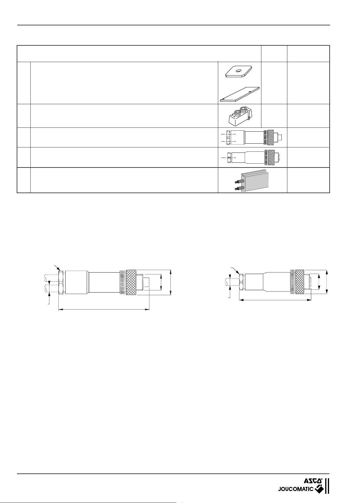
5.7 ACCESSORIES FOR AS-Interface
Description
Valve
series
Codes
A Electrical
Connecting flange for operating ports 2 and 4 with
pressure indicators and instant fittings for flexible hose
Straight 5-pin male duo connector M12 for 2 inputs/outputs (2 cables Ø3 - 5 mm)
Straight 5-pin male mono connector M12 (1 cable Ø 4-6 mm) for 1 input
D Black profiled cable for 24V power supply
(1) (2) These plates can be adapted to islands to block the electrical and pneumatic mounting surfaces of an unused valve place
(removable for further extension).
(3) Length to be specified in metres: max. 100 m (please consult us for longer cables).
(1)
and pneumatic
(2)
blanking plates
+
569
570
571
569
570
881 66 905
881 67 001
881 67 101
881 35 525
881 35 532
881 00 253
881 00 330
881 00 302
(3)
5.8 DIMENSIONS OF THE ACCESSORIES FOR THE AS-Interface
INPUTS (ØM12)
Straight duo connector: 881 00 253
Straight mono connector: 881 00 330
INPUTS (ØM12)
PG11
Ø 3 - 5 mm
PG7
M12
Ø 20
Ø 4 - 6 mm
63
60
M12
Ø 20
20
ILOTS DE DISTRIBUTEURS PNEUMATIQUES
ØM5 - G1/8 - G1/4 ou à coupleurs
à
commande par Bus de terrain avec protocole
AS-Interface
BUSLINK-Génération C
Manuel d'installation
R
W
P
I
S
A
-2
1
IN
-1
1
-4
1
IN
IN
-3
1
-2
2
IN
IN
-1
2
-4
2
IN
IN
-3
2
IN
5
1
3
NTERFACE
N˚ 21401
MS-P586-5.FR.R2a

BUSLINK - AS-Interface INSTALLATION
SOMMAIRE Page
1. Le Système BUSLINK Génération C avec protocole AS-Interface _________________________________ 3
2. Composants du système ___________________________________________________________________ 5
2.1 Description fonctionnelle ____________________________________________________________ 5
2.2 Implantation des composants _________________________________________________________ 5
2.3 Encombrements - Fixation ___________________________________________________________ 6
2.4 Référence d'un îlot BUSLINK Génération C avec AS-Interface _______________________________ 7
2.5 Commande manuelle auxiliaire _______________________________________________________ 8
2.6 Distributeurs séries 569 - 570 - 571 ____________________________________________________ 9
3. Montage du BUSLINK Génération C __________________________________________________________ 10
3.1 Fixation ________________________________________________________________________ 10
3.2 Raccordement pneumatique _________________________________________________________ 10
4. Raccordement électrique ___________________________________________________________________ 12
4.1 Généralités _______________________________________________________________________ 12
4.2 Alimentation en tension _____________________________________________________________ 12
4.3 Calcul de la puissance absorbée ______________________________________________________ 12
4.4 Raccordement des entrées __________________________________________________________ 13
4.5 Adressage des entrées/sorties ________________________________________________________ 14
4.6 Signaux de commande ______________________________________________________________ 16
5. Réseau AS-Interface _______________________________________________________________________
18
5.1 Raccordement du bus AS-Interface (câble jaune) _________________________________________ 18
5.2 Instructions de programmation ________________________________________________________ 18
5.3 Raccordement de la tension d'alimentation (câble noir) ____________________________________ 19
5.4 Mise en service du réseau AS-Interface ________________________________________________ 19
5.5 Diagnostic ________________________________________________________________________ 19
5.6 Fusibles ________________________________________________________________________ 19
5.7 Accessoires pour AS-Interface ________________________________________________________ 20
5.8 Encombrements des accessoires pour AS-Interface _______________________________________ 20
AVERTISSEMENT
Pour le bon fonctionnement des îlots de distributeurs pneumatiques veillez à ce que :
• l'adressage soit correctement paramétré
• toutes interventions d'installation, de réglage et de maintenance doivent être réalisées par un personnel
compétent
Conformément à la directive CEE 89/392/CEE Annexe II B, une Déclaration d’incorporation peut être fournie sur
demande. Veuillez nous indiquer le numéro d’accusé de réception (AR) et les références ou codes des produits
concernés.
Ce produit est conforme aux exigences essentielles de la Directive 89/336/CEE sur la Compatibilité
et amendements. Une déclaration de conformité peut être fournie sur simple demande.
Electromagnétique,
NOTE
Les informations contenues dans le présent manuel sont susceptibles d'être modifiées sans préavis.
ASCO/JOUCOMATIC ne peut être tenu responsable des omissions techniques ou rédactionnelles, ni des dommages
accidentels ou consécutifs à la fourniture ou l'utilisation du présent document.
LE PRESENT MANUEL CONTIENT DES INFORMATIONS PROTEGEES PAR COPYRIGHT, AUCUNE PARTIE DU
PRESENT DOCUMENT NE PEUT ETRE PHOTOCOPIEE OU REPRODUITE SOUS QUELQUE FORME QUE CE SOIT
SANS AUTORISATION ECRITE PREALABLE DE JOUCOMATIC
COPYRIGHT © 1999 - 2000 - ASCO/JOUCOMATIC - Tous droits réservés
2
INSTALLATION BUSLINK - AS-Interface
42
513
14
12
1. LE SYSTEME BUSLINK Génération C avec protocole AS-Interface
Ensemble constitué d'îlots de 4 à 8 distributeurs pneumatiques à commande monostable ou bistable, ØM5 - G1/8 - G1/4, à
connectique intégrée prévue pour raccordement avec automate programmable (API) par liaison série - bus de terrain - via le
protocole de communication normalisé AS-Interface.
Maximum 8 sorties
R
W
P
I
S
A
-2
1
IN
1
1-
-4
1
IN
IN
-3
1
-2
2
IN
IN
-1
2
-4
2
IN
IN
-3
2
IN
5
1
3
N˚ 21401
NTERFACE
3
1
2
1
Distributeurs (nombre maxi : 8 monostables ou 4 bistables)
2
Module boitier de connexion AS-Interface
3
Sur demande - 4 ou 8 entrées
NOTA - Pas de modules d'entrées ou sorties supplémentaires
SCHEMA -TYPE
Maitre
AS-Interface
ASi
Passerelle AS-Interface
vers d'autres protocoles
(Profibus-DP, FIPIO,
Device NET, . . .)
Câble jaune
Câble noir
Alimentation
AS-Interface
AVANTAGES
Par l'étendue de ses possibilités, le système BUSLINK répond aux besoins modernes d'installations automatisées :
• Suppression des faisceaux de fils encombrants
• Economie de temps et de coût des câblages électrique et pneumatique
• Ensemble livré testé, équipé des distributeurs
• Maintenance facilitée
ENSEMBLES REALISABLES
Possibilité de constituer des ensembles Buslink composés :
•
D'îlots de 4, 6 ou 8 distributeurs monostables 3/2 ou 5/2 ou 4 distributeurs
bistables (5/2 - 5/3) ou 4 distributeurs 2x3/2
D'îlots de tailles différentes pour distributeurs séries 569 - 570 - 571 (un îlot ne
•
reçoit qu'une même taille de distributeur)
• Sur demande chaque îlot peut être équipé de 4 embases de connexion M12
à 5 broches femelles pour raccordement de 4 entrées (configuration 1 noeud)
8 entrées (configuration 2 noeuds)
• Distributeurs monostables et bistables à double pilote intégré (
fonctions adaptables sur un même îlot
• Toute configuration réalisable à la demande
), toutes
*
(*) Distributeurs bistables séries 569 - 570 - 571
double pilote intégré (pilotes placés du même
coté pour une solution plus compacte)
ou
24V =
à
3
BUSLINK - AS-Interface INSTALLATION
AS-Interface
Ensemble de distribution pneumatique prévu pour communication
d'informations par bus de terrain via le protocole normalisé ASInterface.
La liaison par bus de terrain entre un système de commande (API)
et un ensemble de modules d'électrodistributeurs pneumatiques
permet de transmettre, par un câble standard AS-Interface, tous les
signaux :
• de commande aux distributeurs
• d'information en provenance des entrées des capteurs
AVANTAGES
Le système Buslink répond aux besoins modernes d'installations
automatisées:
• Suppression des faisceaux de fils encombrants.
• Economie de temps et de coût par câblage électrique directe et
alimentation pneumatique commune.
Visualisation et déconnexion rapide pour une maintenance aisée.
•
• Ensemble livré testé, équipé des distributeurs.
ENSEMBLES REALISABLES
Possibilité de constituer des ensembles Buslink composés de:
•
Distributeurs 3/2, 2x3/2, 5/2 ou 5/3 séries 569 (Ø M5 ou à coupleurs)
570 (G1/8 ou à coupleurs) - 571 (G1/4).
OPTIONS (nous consulter)
• Alimentation pneumatique par 2 pressions différentes.
• Alimentation pneumatique externe des pilotes.
Maitre
AS-Interface
ASi
-
Passerelle AS-Interface vers d'autres protocoles
(Profibus-DP, FIPIO, Device NET, . . .)
R
W
P
I
S
A
-2
1
IN
-1
1
-4
1
IN
IN
-3
1
-2
2
IN
IN
-1
2
-4
2
IN
IN
-3
2
IN
5
1
3
Câble jaune
Câble noir
Alimentation
AS-Interface
24V =
CARACTERISTIQUES DE COMMUNICATION
Protocole : AS-Interface (mode bidirectionnel)
Support de transmission : câble plat AS-Interface (jaune 2 fils)
Structure du bus : optionnelle suivant les recommandations AS-Interface
Nombre maxi d'ensembles : 31 noeuds (1 îlot peut comprendre 2 noeuds)
Nombre de distributeurs par ensemble : 4 à 8 distributeurs
Nombre maxi d'entrées : 8 entrées
Longueur maxi du câble bus : 100 m (300 m avec répéteur)
Adressage des ensembles (abonnés) : par maître AS-Interface
Harmonisation optimale avec automates : pas de modification des programmes existants
Automates compatibles : divers
CARACTERISTIQUES ELECTRIQUES
Tension d'alimentation : 24 V=, ±10% sur l'îlot;
alimentation des distributeurs par câble plat AS-Interface supplémentaire (noir 2 fils)
Taux d'ondulation maxi : 10 %
Consommation : 79 mA par distributeur et 9 mA par entrée
Classe d'isolation (bobines) : F
Degré de protection : IP65
Isolement électrique des entrées : par optocouplage
Protection électrique : intégrée pour chaque bobine
Raccordement supplémentaire de l'alimentation 24V:connecteur intégré à prise vampire pour câble AS-Interface (câble noir)
Raccordement du bus (IN/OUT) : connecteur intégré à prise vampire pour câble AS-Interface (câble jaune)
Raccordement des entrées : par connecteur M12 à 5 broches femelles
Prise de terre : par la vis de mise à la terre sur l'embase pneumatique
Compatibilité électromagnétique : Ces produits sont conformes à la directive européenne CEM 89/336/CEE.
Ils sont certifiés CE
CARACTERISTIQUES PNEUMATIQUES
Fluide distribué : air ou gaz neutre, filtré à 30 µm, lubrifié ou non
Pression d'utilisation : 1,5 à 8 bar (2,5 à 8 bar avec distributeurs 3/2 NO et série 569 fonctions 5/3)
Débit (Qv à 6 bar) série 569 : 175 l/min (ANR)
série 570 : 600 l/min (ANR) (3/2 : 400 l/min - 2x3/2 : 550 l/min)
série 571 : 1050 l/min (ANR)
Température admissible : +5 °C à +50 °C
4

INSTALLATION BUSLINK - AS-Interface
2. COMPOSANTS DU SYSTEME
2.1 DESCRIPTION FONCTIONNELLE
Les ensembles et le système de commande (API) sont liés par 1 câble bus AS-Interface (jaune) pour piloter les distributeurs et relever
les états des capteurs si l'îlot comprend des entrées. Un 2
des distributeurs (câble noir).
L’alimentation en pression et l’échappement sont raccordés sur les embases pneumatiques par canalisations communes. Les
distributeurs établissent l’alimentation en pression et l’échappement des actionneurs pneumatiques. Le raccordement pneumatique
des actionneurs s'effectue sur la face supérieure des distributeurs. Sur demande, l'îlot peut être équipé d’entrées. Les capteurs
électriques sont ainsi raccordables au moyen de connecteurs enfichables ØM12.
CAPACITE MAXIMALE DE L'ILOT
Suivant la configuration choisie, les îlots peuvent recevoir, au maximum, 8 entrées et 8 sorties (1 sortie = 1 pilote de distributeur)
La capacité maximale de l'îlot dépend du nombre de noeuds (voir tableau ci-dessous).
Exemple de configurations maximales :
Nombre de
noeud(s)
Nombre maxi de distri-
buteurs
Nombre maxi
d'entrées
4 monostables
1
ou 2 bistables
ou 2 doubles 3/2 NF
8 monostables
ou 4 bistables
2
ou 4 doubles 3/2 NF
ou 4 monostables +
2 bistables (1)
ème
adaptateur de connexion est utilisé pour l’alimentation en puissance
NOTA :
- Pour 1 noeud , la configuration maximale de l'îlot
est de 4 sorties / 4 entrées
- Pour 2 noeuds, la configuration maximale de
4
l'îlot est de 8 sorties / 8 entrées
- 1 sortie = 1 distributeur monostable
- 2 sorties = 2 distributeurs monostables ou 1 bistable
8
(1) Dans cette configuration les distributeurs bistables sont
toujours à placer à droite sur l'îlot.
2.2 IMPLANTATION DES COMPOSANTS
13
5
Rep. Description
1 Embase de raccordement pneumatique de l'îlot Buslink
2 Module de connexion du Bus AS-Interface
3 Distributeurs 3/2-2x3/2-5/2-5/3 monostables ou bistables (8 maxi)
4 Raccordement taraudé ou à coupleurs des orifices d'utilisation "2-4" (partie supérieure)
5 Raccordement taraudé d'alimentation pneumatique "1" et des échappements "3-5"
6 Bride de raccordement d'alimentation (pour îlot de 8 distributeurs) (voir page 11)
7 LED de visualisation de la mise sous tension des pilotes
8 AS-Interface; adaptateur pour câble du bus AS-Interface (jaune)
9 AS-Interface; adaptateur pour câble d'alimentation AS-Interface supplémentaire (noir)
10 Réglage de l'adresse
2 LED de visualisation de AS-Interface et alimentation
11
8 LED de visualisation des entrées
12 Raccordement des entrées par connecteurs ØM12 (sur demande)
13 Echappement des pilotes 82-84 collecté et raccordable (ØM5)
10 11
8
ASI
IN1-1 IN1-2
NTERFACE
IN1-3 IN1-4
IN2-1
IN2-3 IN2-4
12
9
PWR
IN2-2
7
1
5
1
3
6
2
3 4
5

BUSLINK - AS-Interface INSTALLATION
2.3 ENCOMBREMENTS-FIXATION
L'îlot de distribution comprend 4 trous de fixation
principale sur l'embase des distributeurs complétée
d'une éventuelle fixation de maintien du module de
connexion à l'aide de 2 trous dans l'équerre latérale
gauche. L'entraxe de fixation L2 évolue en fonction
du nombre et de la taille des distributeurs.
Longueur totale de l'îlot : L2 + 77
S'assurer lors du montage qu'il y ait suffisamment de
place à droite pour le raccordement pneumatique et
les éventuels silencieux d'échappement
P1
2 Ø5,5
PWR
ASI
IN1-1 IN1-2
NTERFACE
IN1-3 IN1-4
IN2-1
IN2-2
IN2-3 IN2-4
n2
P3 (1) (2)
P2K2
B
Série
distributeurs
569 (M5)
570 (G1/8)
571 (G1/4)
CK1D
28,5
5 5,5
66,5 L2
L2
n2 : nombre de distributeurs
B C D ØF K1 K2 4 6 8 P1 P2 (1) (2)
163 23 47,5 4,5 60,4 15 91,5 123,5 155,5 3 35 120
163,5 28,3 59 5,5 60,4 21 105 143 181 3 33 130 190
181,5 34,7 70,5 5,5 60,4 26 126,5 172,5 218,5 3 31 170
C
4 ØF
P3
mm
(1) BUSLINK AS-Interface sans entrée :
hauteur nécessaire au câblage pneumatique par tubes rilsan
(les câbles AS-Interface étant placés horizontalement)
(2) BUSLINK AS-Interface avec entrées : hauteur nécessaire au raccordement électrique par connecteurs M12 et câbles de liaison
MASSES
Masse Buslink sans module bus (kg)
Série
distributeurs
n2 : nombre de distributeurs
468
Masse du module de connexion du bus
- sans entrée : 0,550 kg
- avec entrées : 0,600 kg
569
570 (3/2)
570 (5/2-5/3)
571
0,9 1,32 1,73
1,14 1,6 2,06
1,18 1,66 2,14
1,61 2,31 3,01
Masse totale d'un îlot BUSLINK Génération C : définir la masse de la partie électropneumatique en fonction de la série et du nombre
de distributeurs (voir tableau ci-dessus) + la masse du module de connexion du bus (avec ou sans entrées)
6

INSTALLATION BUSLINK - AS-Interface
24
3
5
14
12
1
24
3
5
14
12
1
24
3
5
14
12
1
2.4 REFERENCE D'UN ILOT BUSLINK GENERATION C AVEC AS-Interface
Pour votre commande, nous préciser la référence de la partie électrique 1 ainsi que la référence de la partie pneumatique 2
et les éventuels accessoires
1
■■
■
Partie électrique
■■
TYPE
OPTION
Génération C
E partie Electrique
BI BUSLINK-AS-Interface
OPTION
00 sans option
- -
options ultérieures
}
99
Nombre d'E/S
A1 1 noeud - 4 sorties
A2 1 noeud - 4 sorties / 4 entrées
A3 2 noeuds - 8 sorties
A4 2 noeuds - 8 sorties / 8 entrées
2
■■
■
Partie pneumatique
■■
Génération C
P partie Pneumatique
GR
2 569 (ØM5 ou coupleurs)
3 570 (G1/8 ou coupleurs)
4 571 (G1/4)
Série et taille
des distributeurs
OPTION
00 sans option
- -
options ultérieures
}
99
Type de raccordement
G Orifices taraudés Gaz
N Orifices taraudés NPT
Q à coupleurs (métrique)
Emplacement
ORIFICES : 2 - 4
0 Sur le dessus
Type de raccordement
G Orifices taraudés Gaz
N Orifices taraudés NPT
Emplacement
1 latéral
ORIFICES : 1 - 3 - 5
04
Nombre d'emplacements
06
de distributeurs par îlot
08
(1)
▲
C
E
▼
▼
I
B
▲
▼
-
▼
R
W
P
I
AS
1-2
IN
-1
1
-4
1
IN
IN
-3
1
-2
2
IN
IN
1
2-
-4
2
IN
IN
2-3
IN
A
Possibilité d'équiper l'îlot de 2 ou 4 connecteurs M12 (A) pour raccordement de 4 ou 8
entrées/capteurs suivant le tableau ci-contre.
GR
OPTION
C
P
▲
▲
▲
▲▲▲
Nb places
▲
▲
1234 5678
-
4
6
8
Nombre d'emplacements : - 4 distributeurs bistables ou
- 4 à 8 distributeurs monostables (1)
type
Plaques d'obturations/plans de pose pneu. et élec.
A
Z
K
141214
M
14 1214
J
G
B
E
Fonction des distributeurs
2
1
4
5
4
5
3/2 NF- Cde électropneumatique
3
2
3
1
2
3
1
Rappel ressort/différentiel
2 x
- C
3/2 NF
Rappel différentiel
5/2 - C
Rappel différentiel
5/2 - C
électropneumatiques
5/3 - Centre fermé (W1)
C
5/3 -Centre ouvert à la pression (W2)
C
5/3 -
Centre ouvert à l'échappement (W3)
des
C
de
électropneumatique
de
électropneumatique
de
et rappel
des
électropneumatiques
des
électropneumatiques
électropneumatiques
(1) A définir en fonction des distributeurs, des entrées
et sorties suppplémentaires (voir chapitre 2.1)
EXEMPLE DE COMMANDE :
Référence : CEBI00A4
CP300Q0G106-KKMMJJ
Ilot BUSLINK - Génération C, protocole AS-Interface, avec 2 noeuds, 8 sorties et 8 entrées par 4 connecteurs ØM12. Ensemble prévu
pour 6 emplacements de distributeurs série 570 à sorties par coupleurs pour tubes souples Ø6 mm extr ,
avec les modèles suivants :
- Positions no1 et 2 : 2 distributeurs 3/2 NF monostables, type K
- Positions no3 et 4 : 2 distributeurs 5/2 monostables, type M
- Positions no5 et 6 : 2 distributeurs 5/2 bistables, type J
NOTA : Dans cette configuration les distributeurs bistables sont toujours à placer à droite sur l'îlot.
ACCESSOIRES (voir page 20)
7

BUSLINK - AS-Interface INSTALLATION
2.5 COMMANDE MANUELLE AUXILIAIRE
Les distributeurs séries 569 - 570 - 571 sont équipés de commande(s)
manuelle(s) auxiliaire(s) à impulsion (A).
Distributeur monostable Distributeur bistable
(A)
Type de distributeur
Actions sur
la/les commande(s)
manuelle(s)
(A)
Le distributeur est actionné en position travail tant que la
commande manuelle est maintenue enfoncée (
3/2 - 5/2
monostables
Passage en position rappel lors du relâchement de la
commande manuelle
(A)
(distributeur bistable)
14
12
Fonction du distributeur
42
513
)
*
5/2
bistable
ou
5/3
à position
neutre
5/2
5/3
5/2
5/3
5/2
5/3
5/2
5/3
Le distributeur est actionné en position travail (
(identique à commande 14 actionnée)
Maintien en position travail
Retour à la position neutre centrale
Le distributeur est actionné en position rappel (*)
(identique à fonction rappel 12)
Maintien en position rappel
Retour à la position neutre centrale
*
)
) Ces changements d'état ne sont réalisés que lorsque le distributeur est sous pression.
(
*
Pression d'alimentation sur orifice 1 (1,5 bar mini).
8

INSTALLATION BUSLINK - AS-Interface
2.6
DISTRIBUTEURS SERIES 569 (ØM5) - 570 (G1/8) - 571 (G1/4)
SPECIFICATIONS
FLUIDE DISTRIBUE : Air ou gaz neutre, filtré 30µm, lubrifié ou non
PRESSION D'UTILISATION : 1,5 à 8 bar (2,5 à 8 bar série 569 fonctions 5/3)
TEMPERATURE ADMISSIBLE : +5 °C à +50 °C
FONCTIONS : 3/2 - 2 x 3/2 - 5/2 - 5/3, monostables ou bistables
ORGANES DE PILOTAGE : électropneumatique à alimentation interne
PARTICULARITE : En version double pilote, les 2 pilotes sont intégrés
dans une même tête magnétique monobloc placée
d'un seul côté = solution plus compacte (voir page 5)
CONSTRUCTION
DISTRIBUTEUR
Corps en alliage d'aluminium et
couvercle en thermoplastique (PA-Ar)
Pièces internes en acier inoxydable, alliage d'aluminium,
et résine acétal (POM)
Joints d'étanchéité en nitrile (NBR)
PILOTE
Etanchéité par garniture en nitrile (NBR)
Appareillage électrique conforme à la norme NF C79300
Bobinage et circuit magnétique monobloc surmoulés
Commande(s) manuelle(s) à impulsion
CARACTERISTIQUES ELECTRIQUES
TENSION D'ALIMENTATION : 24V CC ±10%,
ondulation maxi 10%
PUISSANCE ABSORBEE : 1,7 W (par bobine)
CLASSE D'ISOLATION : F
DEGRE DE PROTECTION : IP 65
Distributeur
monostable
(A)
Distributeur
bistable
(A)
1 = Pression 12 = Rappel
2 - 4 = Utilisations 14 = Commande
3 - 5 = Echappements
Distributeur 570 (2 x 3/2)
Distributeur 570 (5/2)
SELECTION DU MATERIEL
Symboles
Fonctions
TYPE
(1)
2
3/2
Z
NF
3
1
2 x
K
3/2
2
4
141214
5/2
M
5/2
J
14
5/3
G
14
5/3
B
14
5/3
E
Possibilité d'utiliser les distributeurs 5/2 en fonction 3/2 NF, (en obturant l'orifice 2) ou 3/2 NO (en obturant l'orifice 4).
(1) Les fonctions de la nouvelle construction à double pilotes intégrés restent identiques à la version classique.
La symbolisation reste conforme à ISO 1219-1
NOTA - Toutes les versions ci-dessus peuvent être montées et combinées sur le même îlot, dans une même taille.
5
3
1
2
4
14 1214
5
3
1
24
5
1
24
5
3
1
24
5
1
12
3
12
12
3
Organes de pîlotage
Commande
(14)
Electro-
pneumatique
Electro-
pneumatique
Electro-
pneumatique
Electro-
pneumatique
Centre fermé
commandes
électropneumatiques
Centre ouvert
à la pression
commandes
électropneumatiques
Centre ouvert
à l'échappement
commandes
électropneumatiques
Différentiel
Différentiel
Différentiel
pneumatique
W1
W2
W3
Rappel
(12)
Ressort/
Electro-
GR
3 (570)
(570)
3
2 (569)
3 (570)
4 (571)
2 (569)
3 (570)
4 (571)
2 (569)
3 (570)
4 (571)
2 (569)
3 (570)
4 (571)
(569)
2
3 (570)
4 (571)
à coupleur pour tube
souple Ø6 mm ext
Ø
raccordement
orifices
d'utilisations
G1/8
G1/8
M5
G1/8
G1/4
M5
G1/8
G1/4
M5
G1/8
G1/4
M5
G1/8
G1/4
M5
G1/8
G1/4
Ø
pas-
sage
(mm)
r
5
5
2,5
4
6
2,5
4
6
2,5
4
6
2,5
4
6
2,5
4
6
Débit
à 6 bar
(l/min)
ANR
400
550
175
600
1050
175
600
1050
175
600
1050
175
600
1050
175
600
1050
CODES
DISTRIBUTEURS
(24 V =)
570 00 053
570 00 051
570 00 103
569 00 012
570 00 012
571 00 012
569 00 014
570 00 014
571 00 014
569 00 016
570 00 016
571 00 016
569 00 018
570 00 018
571 00 018
569 00 020
570 00 020
571 00 020
9

BUSLINK - AS-Interface INSTALLATION
3 MONTAGE DU BUSLINK Génération C avec AS-Interface
3.1 FIXATION
Effectuer la fixation de l'îlot (voir chapitre 2.3)
S'assurer lors du montage qu'il y ait suffisamment de place pour le câblage, les connecteurs et les éventuels silencieux d'échappement. Puis procéder au raccordement pneumatique et électrique.
A
Alimentation pression 1
et échappements 3 - 5
B
Utilisations 2 - 4
C
Raccordement du bus (câble jaune)
D
Alimentation des distributeurs 24 V CC (câble noir)
E
Entrées détecteurs (sur demande)
C
C
D
V
4
2
I
S
A
2
N
I
1
1
N
I
4
1
N
I
1
3
N
I
2
1
N
I
2
1
N
I
4
2
N
I
2
3
N
I
2
5
D
1
3
E
3.2 RACCORDEMENT PNEUMATIQUE
3.2.1 GENERALITES
■■
■ Sur l’embase
■■
L' embase comporte les canaux pour collecter les signaux pneumatiques communs : pression d'alimentation (1), Echappements (3) et (5),
et échappement des électrovannes pilotes. Les orifices de raccordement sont disposés sur le coté droit de l'embase, ou pour certaines
versions d'îlots les orifices de raccordement se trouvent aussi à gauche des distributeurs (voir ci-contre)
82-84
5
1
A
3
B
■■
■ Sur les distributeurs
■■
Deux possibilités de raccordement des orifices d’utilisations (2 - 4) sur la face supérieure:
- raccords taraudés directement sur le corps du distributeur
- raccords instantanés par coupleurs tubes souples (sur distributeurs séries 569 et 570).
■■
■ Procédure de raccordement
■■
- Enlever tous les bouchons de protection en plastique.
- Pour les ØM5 ou raccords orientables type banjo, placer le joint (généralement fourni avec le raccord)
- Visser correctement les raccords
- Visser les silencieux d'échappement.
- Raccorder les canalisations pneumatiques. Lier les tubes afin d’obtenir un câblage propre et accessible.
■ Recommandation de raccordement de l'alimentation de pression (voir page suivante)
■ Raccordements
Série
Orifice d'alimentation
Orifices d'échappement
Orifices d'échappement
Orifices d'utilisations
des pilotes
(1)
(3) (5)
(82/84)
(2) (4)
569 G 1/8 G 1/8 M 5 M 5 (❇)
(3/2-2x3/2)
570
G 1/4 G 1/4 M 5
à coupleur
G1/8
570 (5/2-5/3) G 1/4 G 1/4 M 5 G 1/8 (❇)
571 G 3/8 G 3/8 M 5 G 1/4
(❇) ou par bride à coupleurs rapides pour tubes souples :
• Ø 4 mm extérieur (569)
• Ø 6 mm extérieur (570)
Version taraudée Version à bride à coupleurs
10
2
4
2
4

INSTALLATION BUSLINK - AS-Interface
3.2.2 RACCORDEMENT DE L'ALIMENTATION DE PRESSION
■ Alimentation par 1 pression (P1)
- Ilot de 4 à 6 distributeurs; raccordement de l'alimentation coté droit
Série
NTERFACE
ASI
IN1-1 IN1-2
IN1-3 IN1-4
IN2-1
IN2-3 IN2-4
PWR
IN2-2
+
+
5
P1
1
3
distributeurs
569 G1/8
570 G1/4
571 G3/8
Recommandation de montage
Cinq distributeurs peuvent fonctionner simultanément, au maximum sans perturbation pneumatique.
- Ilot de 8 distributeurs
Au-delà de 6 distributeurs il faut alimenter l'ensemble des 2 cotés, à cet effet les îlots de 8 distributeurs sont toujours
fournis avec une bride de connexion.
PWR
ASI
IN1-1 IN1-2
NTERFACE
IN1-3 IN1-4
IN2-1
IN2-2
IN2-3 IN2-4
5
5
1
P1
1
I
S
A
1
1
N
I
3
1
N
I
1
2
N
I
3I
2
N
I
R
W
P
2
-
1
N
I
4
-
1
N
I
2
-
2
N
I
4
-
2
N
5
1
3
3
P1
3
Orifices
1 - 3 - 5
P1
■ Alimentation par 2 pressions différentes (P1 - P2)
Possibilité d'alimenter 1 à 4 distributeurs à une pression P2 (nous consulter)
■ Alimentation externe des pilotes (nous consulter)
11
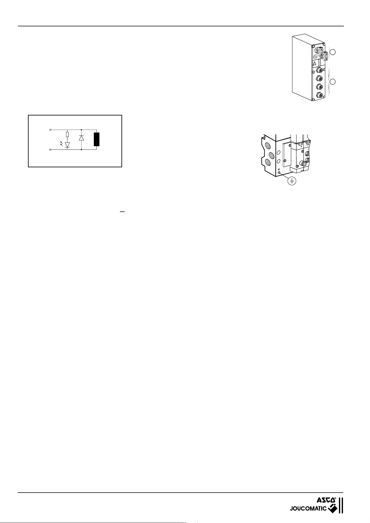
BUSLINK - AS-Interface INSTALLATION
1
3
5
4 RACCORDEMENT ELECTRIQUE
4.1 GENERALITES
Les îlots sont équipés de 2 connecteurs AS-Interface à prises vampires pour raccordement du réseau bus et
l'alimentation (B) et sur demande, de 2 ou 4 embases de connexion M12 à 5 broches femelles pour les entrées (A).
Pour effectuer les connexions il est nécessaire d'approvisionner les câbles et connecteurs M12 complémentaires.
Circuit de protection électrique intégré pour chaque bobine.
Mise à la terre
La mise à la terre pour la protection des
V N.N
personnes est à réaliser directement sur
l'îlot en raccordant la vis prévue à cet effet
Bobine
Coil
Spule
GND
4.2 ALIMENTATION EN TENSION
- Le câble jaune alimente l'interface AS-Interface
- Le câble noir alimente les distributeurs et les entrées
Tension d'alimentation : 24 V=, ±10%
Ondulation résiduelle : ±10 %
Consommation : 1,7 par bobine, + 0,2 W par LED
maxi 5 W / électronique bus
Entrées: courant cumulé < 0,5 A
Calcul de la puissance absorbée (voir ci-dessous)
Vérifier la tension d'alimentation pendant que l'installation est en service
et s'assurer que les tolérances admissibles sont respectées (±10%)
B
R
W
P
I
S
A
-2
1
IN
1
-
1
-4
1
IN
IN
-3
1
-2
2
IN
N
I
-1
2
-4
N
2
I
IN
-3
2
IN
A
4.3 CALCUL DE LA PUISSANCE ABSORBEE
La puissance absorbée d'un îlot dépend de sa configuration
Le calcul de cette puissance permettra à l'utilisateur d'optimiser la définition de l'alimentation 24 V nécessaire.
Consommation des divers éléments:
- Consommation de l'électronique Bus : 40 mA
- Consommation d'une entrée : 9 mA
- Consommation d'un distributeur + led : 79 mA
12
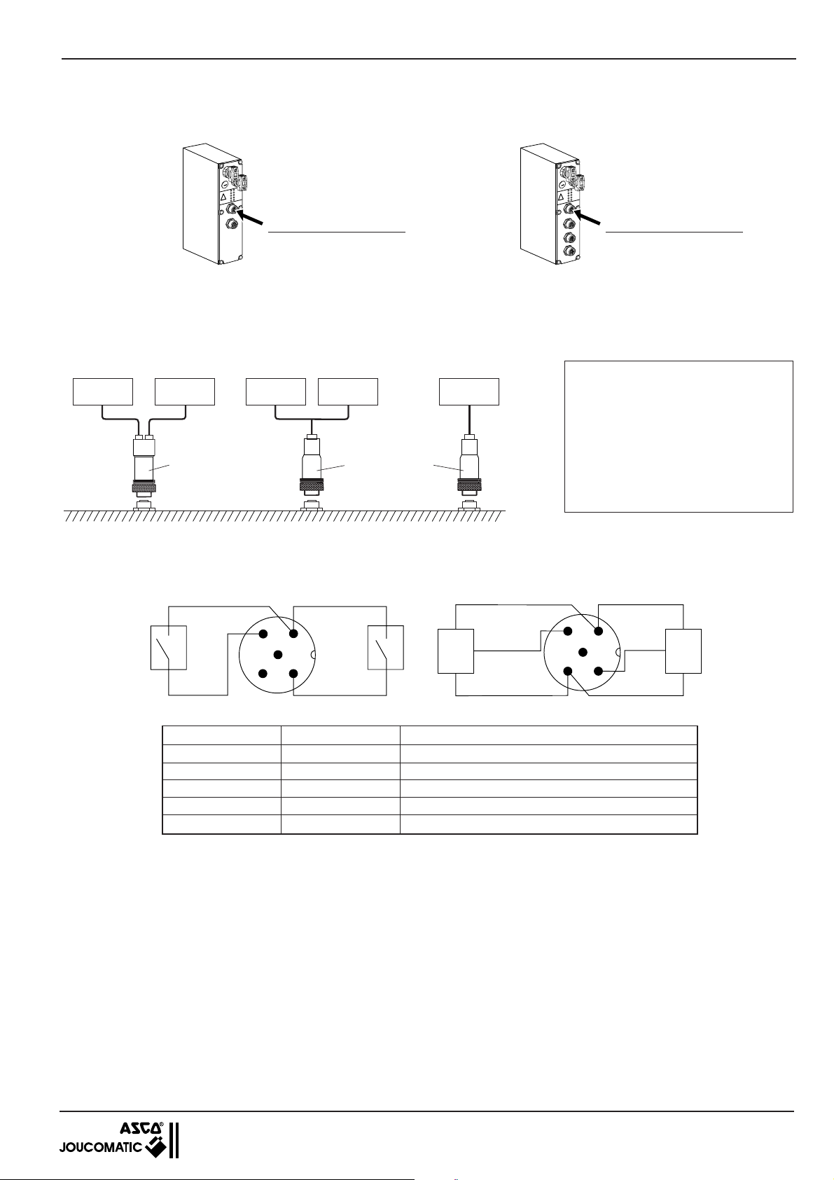
INSTALLATION BUSLINK - AS-Interface
1
2
4
3
5
+
-
+
-
4.4 RACCORDEMENT DES ENTREES (Entrées sur demande)
Raccordement par connecteurs M12 débrochables IP65.
Possibilité de raccorder des capteurs à 2 ou 3 fils.
Equipé de 2 embases de
connexion M12 pour 4 entrées
R
W
P
I
S
A
2
-
1
N
I
1
-
1
4
-
N
1
I
N
I
3
2
1
-
N
2
I
N
I
1
-
2
4
-
N
I
2
N
I
3
-
2
N
I
(2 entrées par connecteur)
Adressage des entrées :
x : IN1-1, IN1-3
X + 1 : IN1-2, IN1-4
(voir chapitre 4.5)
RACCORDEMENT SUR CONNECTEUR M12
Deux modèles de connecteurs M12 sont proposés :
- Connecteur droit duo (A) pour raccordement de 2 câbles individuels (un par capteur)
- Connecteur droit mono (B) pour raccordement d'un capteur ou câblage regroupé
Capteur Capteur Capteur Capteur Capteur
(A) 881 00 253
Repérage vu coté vissage du connecteur mâle
● capteurs à 2 fils ● capteurs à 3 fils (exemple : magnéto-résistif)
24V 24V
(B) 881 00 330
Schéma de raccordement des entrées
24V 24V
Equipé de 4 embases de
connexion M12 pour 8 entrées
R
W
P
I
S
A
2
1
N
I
1
1
4
-
N
1
I
N
I
3
2
1
-
N
2
I
N
I
1
2
4
-
N
I
2
N
I
3
-
2
N
I
(2 entrées par connecteur)
Adressage des entrées :
x : IN1-1, IN1-3, IN2-1, IN2-3
X + 1: IN1-2, IN1-4, IN2-2, IN2-4
(voir chapitre 4.5)
Connecteur à approvisionner :
(A) Connecteur duo droit M12
à 5 broches mâles
passage de chaque câble Ø3 à 5 mm
code : 881 00 253
(B) Connecteur mono droit M12
pour 1 entrée de câble Ø 4 à 6 mm
à 5 broches mâles
code : 881 00 330
1
Capteur
5
x+1
IN x+1
2
Capteur
x
IN x
IN
x+1
GND GND
Capteur
x+1
Capteur x
IN x
4
3
Broche Nom Description
1 24V DC IN Alimentation des entrées
2 IN x +1 Entrée logique positive x + 1
3 GROUND Commun (capteurs à 3 fils)
4 IN x Entrée logique positive x
5 PE mise à la terre
REMARQUE :
L'état des capteurs raccordés peut-être interrogé à travers les entrées. Les entrées disposent d'une logique positive, elles peuvent être
opérées ensemble avec des capteurs à sorties pnp. les entrées sont "LOW" et doivent être commutées à + 24 V (HIGH) pour être
activées.
courant d'entrée typique : 9 mA à 24 VCC
● Etat logique "LOW" : < 8 V ● Etat logique "HIGH" : > 14 V
Tension d'entrée maxi en cas d'alimentation externe des entrées : 40 V
Lors du raccordement de capteurs 2 fils, le courant résiduel doit être < 1 mA.
En état "LOW", le courant résiduel alimenté à l'entrée doit être < 1 mA.
13
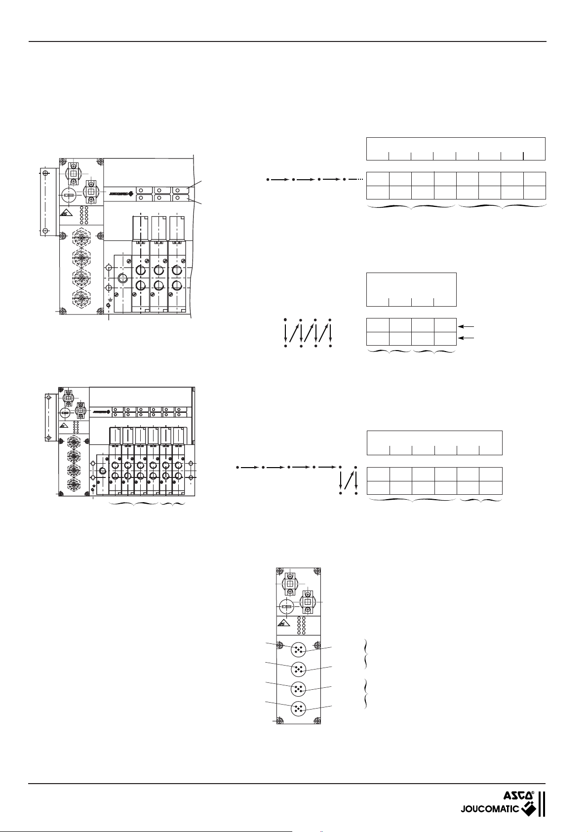
BUSLINK - AS-Interface INSTALLATION
4.5 ADRESSAGES
4.5.1 ADRESSAGE DES DISTRIBUTEURS
Signaux de commande des distributeurs (voir chapitre 4.6)
Le mode d'adressage des distributeurs est différent suivant le type de produits (monostable ou bistable)
■ Distributeurs monostables (maxi = 8)
progression de l'adressage: horizontale
Position des distributeurs
12345678
adressage :
V0.0 V0.2 V0.4 V0.6 V1.0 V1.2 V1.4 V1.6
__ ______
1er noeud 2
eme
noeud
Position des
distributeurs
1234
adressage :
V0.0 V0.2 V0.4 V0.6
V0.1 V0.3 V0.5 V0.7
1er noeud
2
eme
noeud
Signaux de
commande (14)
Signaux de
rappel (12)
ASI
IN1-1 IN1-2
IN1-3 IN1-4
IN2-1
IN2-3 IN2-4
Signaux de
commande
PWR
IN2-2
Signaux
de rappel
■ Distributeurs bistables (maxi = 4)
le poids des adresses progresse du haut en bas puis de la
gauche vers la droite
PWR
ASI
IN1-1 IN1-2
IN1-3 IN1-4
IN2-1
IN2-2
IN2-3 IN2-4
4 monostables
(1er noeud)
2 bistables
eme
(2
noeud)
4.5.2 ADRESSAGE DES ENTREES
■ NOTA: en configuration 2 noeuds il est possible de panacher des
distributeurs monostables et des bistables (maxi = 4 mono et
2 bistables) Ceux-ci sont toujours disposés comme ci-contre.
Dans ce cas, la progression d'adressage est la suivante :
Ilot AS-Interface avec entrées
PWR
ASI
IN1-1 IN1-2
IN1-3 IN1-4
IN2-1
IN2-2
IN1-1
IN1-3
IN2-1
IN2-3
IN2-3 IN2-4
IN1-2
IN1-4
IN2-2
IN2-4
Position des distributeurs
123456
adressage :
V0.0 V0.2 V0.4 V0.6 V1.0 V1.2
__ __
1er noeud
V1.1 V1.3
eme
2
noeud
1er noeud
eme
2
noeud
Raccorder 2 capteurs (2 entrées) par connecteur M12 (voir page précédente)
14
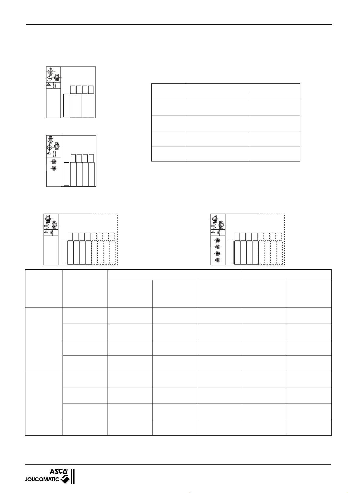
INSTALLATION BUSLINK - AS-Interface
4.5.3 RECAPITULATIF DES ADRESSAGES
■ Ilot AS-Interface 1 noeud
4 distributeurs monostables
(référence îlot : A1)
PWR
ASI
IN1-1 IN1-2
NTERFACE
IN1-3 IN1-4
IN2-1
IN2-2
IN2-3 IN2-4
+
234
1
+
4 distributeurs monostables et 4 entrées
(référence îlot : A2)
PWR
ASI
IN1-1 IN1-2
NTERFACE
IN1-3 IN1-4
IN2-1
IN2-2
IN2-3 IN2-4
+
234
1
+
Bit de
donnée
D0
D1
D2
D3
Distributeurs Entrées
Distributeur n°1 / 14 Entrée 1
V0.0 IN1-1
Distributeur n°2 / 14 Entrée 2
V0.2 IN1-2
Distributeur n°3 / 14 Entrée 3
V0.4 IN1-3
Distributeur n°4 / 14 Entrée 4
V0.6 IN1-4
Adressage
■ Ilot AS-Interface 2 noeuds
8 distributeurs monostables ou 4 bistables 8 distributeurs monostables ou 4 bistables et 8 entrées
(référence îlot : A3) (référence îlot : A4)
NTERFACE
ASI
IN1-1 IN1-2
IN1-3 IN1-4
IN2-1
IN2-3 IN2-4
PWR
IN2-2
+
678
234
1
+
5
NTERFACE
ASI
IN1-1 IN1-2
IN1-3 IN1-4
IN2-1
IN2-3 IN2-4
PWR
IN2-2
+
234
1
+
5
678
Adressage distributeurs Adressage entrées
4 distributeurs
Numéro
de noeud
Bit
de donnée
8 distributeurs
monostables
4 distributeurs
bistables
monostables et
2 distributeurs
4 entrées 8 entrées
bistables
D0
D1
1
D2
D3
D0
D1
2
D2
D3
Distributeur 1/14 Distributeur 1/14 Distributeur 1/14 Entrée 1 Entrée 1
V0.0 V0.0 V0.0 IN1-1 IN1-1
Distributeur 2/14 Distributeur 1/12 Distributeur 2/14 Entrée 2 Entrée 2
V0.2 V0.1 V0.2 IN1-2 IN1-2
Distributeur 3/14 Distributeur 2/14 Distributeur 3/14 Entrée 3 Entrée 3
V0.4 V0.2 V0.4 IN1-3 IN1-3
Distributeur 4/14 Distributeur 2/12 Distributeur 4/14 Entrée 4 Entrée 4
V0.6 V0.3 V0.6 IN1-4 IN1-4
Distributeur 5/14 Distributeur 3/14 Distributeur 5/14
V1.0 V0.4 V1.0 IN2-1
Distributeur 6/14 Distributeur 3/12 Distributeur 5/12
V1.2 V0.5 V1.1 IN2-2
Distributeur 7/14 Distributeur 4/14 Distributeur 6/14
V1.4 V0.6 V1.2 IN2-3
Distributeur 8/14 Distributeur 4/12 Distributeur 6/12
V1.6 V0.7 V1.3 IN2-4
_
_
_
_
Entrée 5
Entrée 6
Entrée 7
Entrée 8
Distributeur X/14 = mise sous tension bobine "Commande" 14 : Orifice 4 sous pression
Distributeur X/12 = mise sous tension bobine "Rappel" 12 : Orifice 2 sous pression
(1)Sauf distributeur 3/2 NF monostable série 570 coté commande = 12 (orifice 2 sous pression). Rappel par mise hors tension de la
bobine 12 (voir signaux de commande : chapitre 4.6, pages suivantes)
15
BUSLINK - AS-Interface INSTALLATION
141214
2
3
5
4
1
1
14 1214
2
3
5
4
1
P
0
P
0
24 V
0 V
24 V
0 V
2
2
W2 (B) W3 (E) W1 (G)
24
3
5
14
12
1
4.6 SIGNAUX DE COMMANDE
■ DISTRIBUTEUR 5/2 MONOSTABLE (rappel pneumatique différentiel) - Type : M
Orifice 2
0
P
P
Orifice 4
0
24 V
Signal électrique coté 12
0 V
24 V
Signal sur bobine 14 (commande)
0 V
■ DISTRIBUTEUR 5/2 BISTABLE - Type : J
Orifice 2
Orifice 4
Signal sur bobine 12 (Rappel)
P
0
P
0
24 V
0 V
non nécessaire (pas de bobine 12, rappel différentiel)
1
P = Pression
Ces signaux peuvent être
impulsionnels ou maintenus
jusqu'au changement d'état
souhaité.
Signal sur bobine 14 (Commande)
24 V
■ DISTRIBUTEUR 5/3 - Types : B - E - G
Orifice 2
Orifice 4
Signal sur bobine 12
Signal sur bobine 14
1
0 V
14
24
5
1
12
3
24
14
5
1
12
3
2
En version 5/3 centre fermé, type W1, les pressions en 2 et 4 sont celles qui étaient présentes au moment de la mise hors tension
des bobines 12 et 14.
16

INSTALLATION BUSLINK - AS-Interface
P
0
P
0
24 V
0 V
24 V
0 V
P
0
P
0
24 V
0 V
24 V
0 V
■ DISTRIBUTEUR 570 3/2 NF MONOSTABLE - Type : Z
12
2
3
1
Orifice 2
P
0
(*) Considérer le signal 14 pour l'adressage
bobine 12 (
DISTRIBUTEUR 5/2 MONOSTABLE OU BISTABLE UTILISÉ EN 3/2 NF (obturer l'orifice 2)
■
)
0 V
*
24 V
et le raccordement de la commande des
distributeurs 3/2 NF
MONOSTABLE
2
4
141214
5
3
1
Orifice 2
Obturé
Orifice 4
Signal sur bobine 12
non nécessaire (rappel différentiel)
Obturé
BISTABLE
14 1214
2
4
5
3
1
Signal sur bobine 14
■ DISTRIBUTEUR 5/2 MONOSTABLE OU BISTABLE UTILISÉ EN 3/2 NO (obturer l'orifice 4)
MONOSTABLE
2
4
141214
5
3
1
Orifice 2
P
0
24 V
P
Obturé
0
Orifice 4
Signal sur bobine 12 non nécessaire (rappel différentiel)
0 V
Signal sur bobine 14
24 V
0 V
P
0
P
0
24 V
0 V
24 V
0 V
Obturé
BISTABLE
14 1214
2
4
5
3
1
17

BUSLINK - AS-Interface INSTALLATION
X
5 RESEAU AS-Interface
5.1 RACCORDEMENT DU BUS AS-Interface
La face avant de l'îlot de distributeurs pneumatiques prévu pour AS-Interface est équipée d'un adaptateur à prises vampires pour
raccordement instantané, sans vis ni dénudage du câble plat profilé bus AS-Interface jaune. Ce dernier permet le transfert des
données et l'alimentation des entrées capteurs
■■
■ Raccordement du bus AS-Interface
■■
Passerelle
AS-
Interface
Maître
PC
AS-
Interface
24V =
■■
■ Raccordement sur Maître AS-Interface
■■
AS-Interface
Marron
+
_
Maître
NOTA - Réaliser les instructions de programmation
avant de raccorder le câble noir d'alimentation
Bleu
C
C
NOTA : Lors de la connexion sur l'îlot respecter le sens de
montage du câble et de l'adaptateur (pour ce dernier,
détrompage par largeurs différentes des pattes latérales)
■■
■ Raccordement AS-Interface sur l'îlot
■■
C
X
Câble AS-Interface jaune
Adaptateur pour connecteur AS-Interface
Cet adaptateur est fourni avec l'îlot.
5.2 INSTRUCTIONS DE PROGRAMMATION
Se référer au manuel du constructeur AS-Interface
5.2.1 REGLAGE DE L'ADRESSE
1 -
Dévisser le bouchon fileté pour accéder à l'interrupteur
de découplage
2 - Mettre l'interrupteur sur numéro (1) et connecter
l'îlot au maître ou à la pocket de programmation
1
2
3
NTERFACE
ASI
IN1-1 IN1-2
IN1-3 IN1-4
IN2-1
IN2-3 IN2-4
Position
du switch
1
2
PWR
IN2-2
3
1
2
3
1
2
3
Numéro
du noeud
1
2
1 + 2
adressage
noeud 1
adressage
noeud 2
Mode
RUN
3 - Affecter l'adresse pour le 1
er
noeud ou par la
pocket, incrémenter ou décrémenter et faire "write"
4 - Mettre l'interrupteur sur numéro (3)
ème
5 - Affecter l'adresse pour le 2
noeud ou par la
pocket, incrémenter ou décrémenter et faire "write"
6 - Mettre l'interrupteur sur numéro 2
7 - Les 2 adresses sont ainsi mémorisées dans l'îlot.
Remonter le bouchon fileté
5.2.2 REGLAGE DE LA VITESSE DE TRANSMISSION
Elle est figée et donnée par le maître AS-Interface
5.2.3 CONFIGURATION DE LA CARTE CONTROLEUR AVEC LES ÎLOTS
Dans le cas où la configuration du réseau AS-Interface se fait avec coupleur AS-Interface intégré à l'automate, voici les codes
d'identification pour un îlot JOUCOMATIC AS-Interface
Code
Entrées/sorties
ID-code
Code identificateur d'un îlot JOUCOMATIC 7 F
18
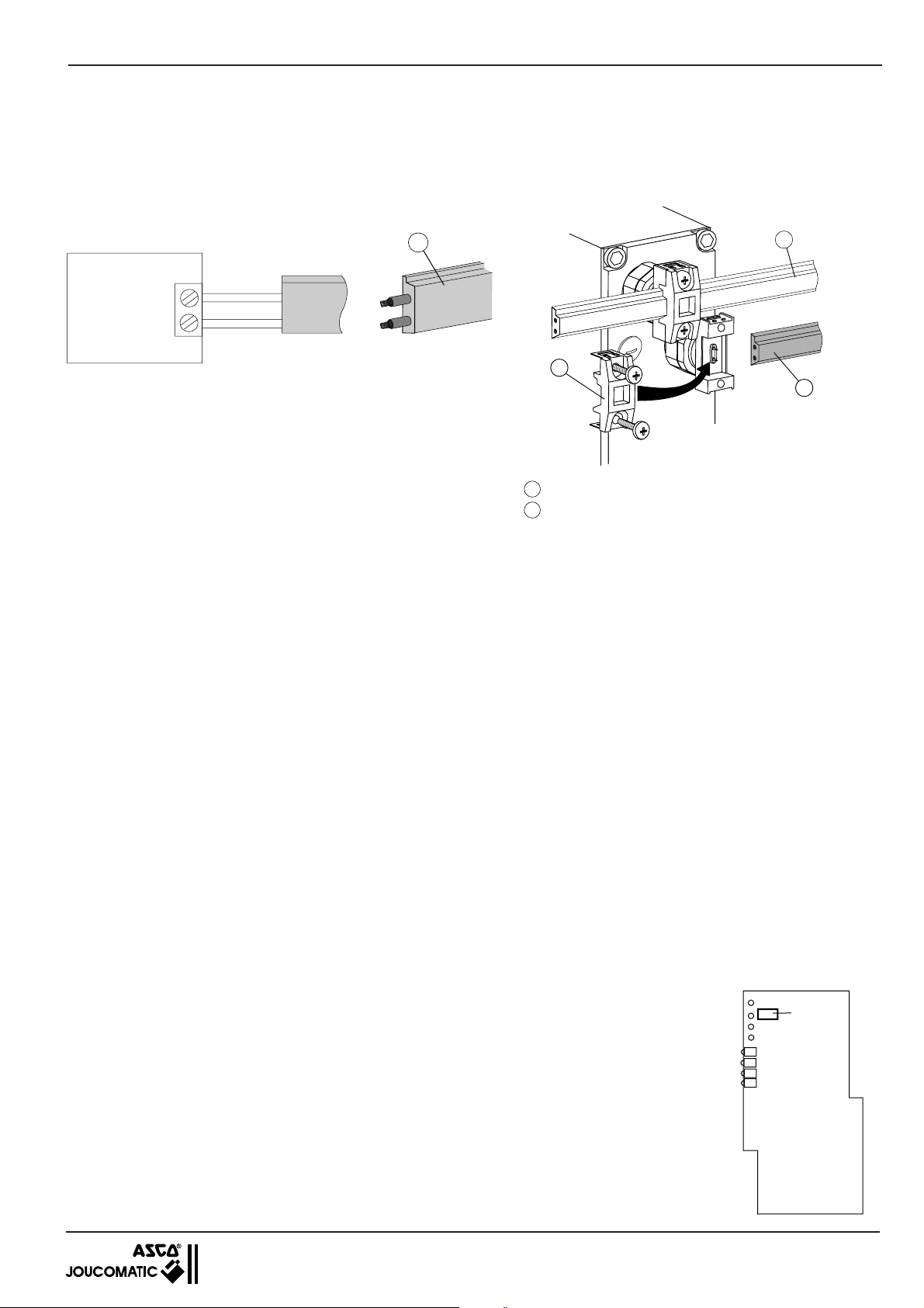
INSTALLATION BUSLINK - AS-Interface
D
X
C
5.3 RACCORDEMENT DE LA TENSION D'ALIMENTATION
Cette connexion est à réaliser après avoir effectué toutes les instructions de programmation (voir chapitres précédents).
Le raccordement de la tension de service s'effectue sur la face avant de l'îlot à l'aide du câble profilé AS-Interface noir et du connecteur
à prises vampires. Connexion instantanée sur l'îlot, sans vis ni dénudage du câble, par clipsage de l'adaptateur (voir ci-dessous).
■■
■ Raccordement sur boitier d'alimentation ■ Raccordement de l'alimentation sur l'îlot
■■
D
Marron
24V =
Alimentation
+
_
Bleu
Câble AS-Interface noir
D
Adaptateur pour connecteur AS-Interface
X
Cet adaptateur est fourni avec l'îlot.
NOTA : Lors de la connexion sur l'îlot respecter le sens de
montage du câble et de l'adaptateur (pour ce dernier,
détrompage par largeurs différentes des pattes latérales)
5.4 MISE EN SERVICE DU RESEAU AS-Interface
1 - Connecter le câble jaune
2 - Connecter le câble noir
3 - Mettre en route le maître AS-Interface
5.5 DIAGNOSTIC
5.5.1 LED DE VISUALISATION
SUR LE MODULE BUSLINK :
Le module Buslink AS-Interface dispose de 2,6 ou 10 LED de diagnostic (suivant les versions)
AS-Interface (vert)
•
• POWER (vert) S'allume lorsque le 24V du câble noir des distributeurs est présent
• IN1-1 .... IN1-4 4 led (îlot 1 noeud avec 4 entrées) qui s'allument lorsque les capteurs sont actionnés
• IN1-1 .... IN2-4 8 led (îlot 2 noeuds avec 8 entrées) qui s'allument lorsque les capteurs sont actionnés
S'allume lorsque la communication est possible
5.5.2 REGISTRE DIAGNOSTIC
Voir info AS-Interface
5.5.3 POSITION DE REPLI
Les îlots AS-Interface ont une position de repli à zéro.
5.6 FUSIBLES
L'alimentation en tension par le câble noir est protégée par un fusible intégré dans le boîtier du module bus.
On peut le remplacer en dévissant le couvercle du boîtier du module. Otez-le avec une pince mince.
N’utilisez que des fusibles du même type et de la même valeur en rechange.
(A)
(A) Fusible type 20 x 5mm 250V/2A,
lot de 10 fusibles de rechange (pour sorties), code : 881 00 346
19
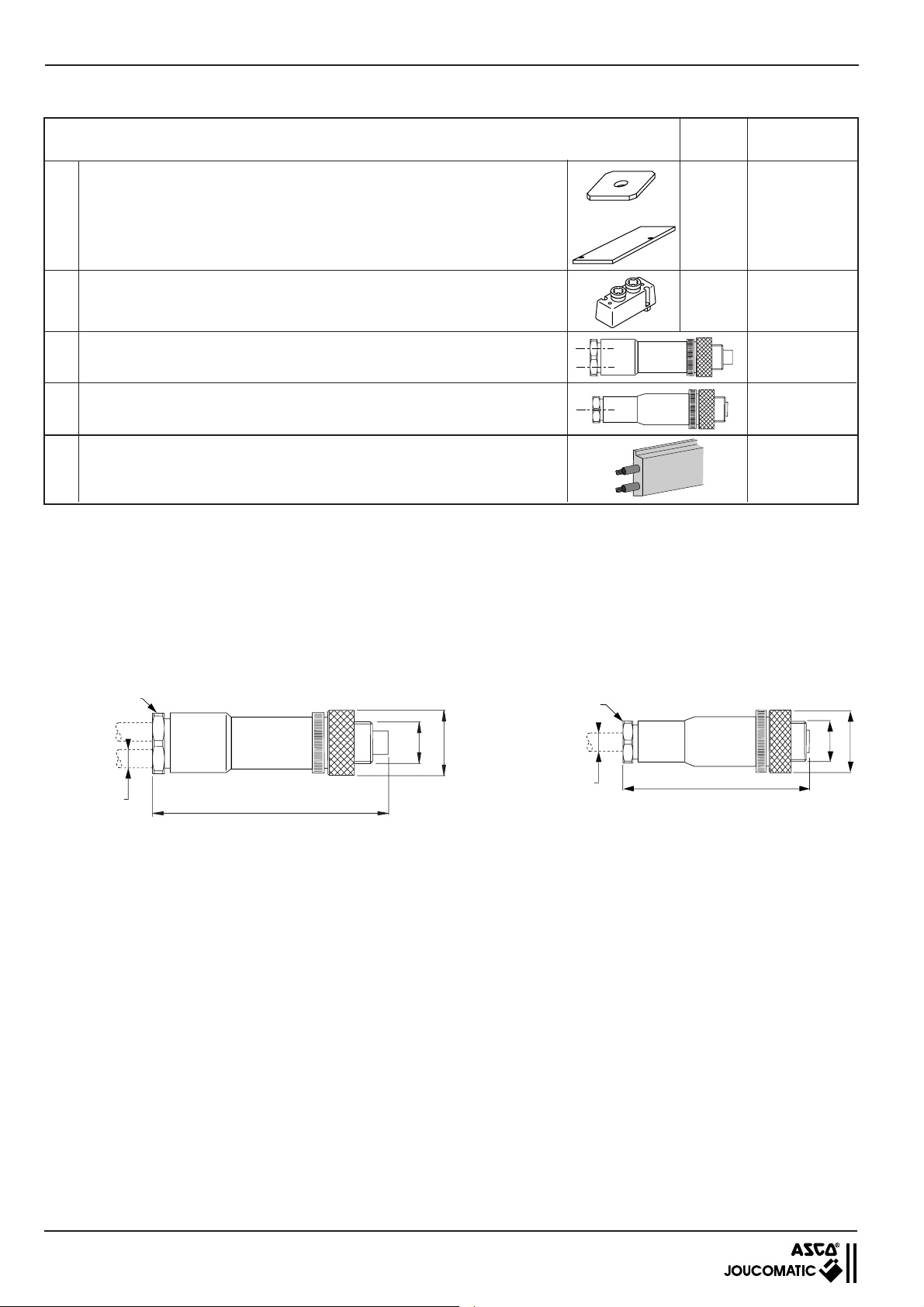
BUSLINK - AS-Interface INSTALLATION
5.7 ACCESSOIRES POUR AS-Interface
Désignation
Distri-
buteurs
Codes
A Plaques d'obturation des plans de pose électrique
Bride de connexion pneumatique des orifices d'utilisations 2 et 4 prévue
avec témoins de pression et coupleurs pour tube souple
Connecteur duo droit M12 à 5 broches mâles pour 2 entrées Ø3 - 5 mm
Connecteur mono (1 câble Ø4-6 mm) droit M12 à 5 broches mâles pour entrées
D Câble noir profilé pour alimentation 24V
(1) (2) Plaques destinées à obturer les plans de pose électrique et pneumatique d'un emplacement d'électrodistributeur laissé
libre pour une extension ultérieure
(3) Longueur en mètres à préciser à la commande : 100 m maxi (au delà, nous consulter).
(1)
et pneumatique
(2)
+
569
570
571
569
570
881 66 905
881 67 001
881 67 101
881 35 525
881 35 532
881 00 253
881 00 330
881 00 302
5.8 ENCOMBREMENTS DES ACCESSOIRES POUR AS-Interface
ENTREES (ØM12)
connecteur DUO droit : 881 00 253
Connecteur mono droit : 881 00 330
ENTREES (ØM12)
(3)
PG11
Ø 3 - 5 mm
PG7
M12
Ø 20
Ø 4 - 6 mm
63
60
M12
Ø 20
20
 Loading...