

Page 1

Advanced Redundant Control
System (ARCS)
Direct Acting Platform
-141 Series
Safety Manual for Safety Integrated system
ASCO Valves
No. 57, Kundrathur Main Rd., Gerugambakkam, Chennai -6000128, India www.asco.com Page 1 of 24
®
E290115 - 12/2018
All Rights Reserved.
IM-IND-536661-Rev AA
Page 2

TABLE OF CONTENTS
1 INTRODUCTION ......................................................................................................................... 3
1.1 TERMS AND ABBREVIATIONS ................................................................................................ 3
1.2 ACRONYMS ........................................................................................................................ 3
1.3 PRODUCT SUPPORT............................................................................................................ 4
1.4 RELATED LITERATURE ......................................................................................................... 4
1.5 REFERENCE STANDARDS .................................................................................................... 4
2 ARCS DIRECT ACTING DESCRIPTION ........................................................................................ 4
2.1 REDUNDANT CONFIGURATIONS ............................................................................................ 4
2.2 REDUNDANT FUNCTIONS ..................................................................................................... 4
3 DESIGNING A SAFETY INSTRUMENTED FUNCTION USING AN ASCO ARCS ................................. 5
3.1 SAFETY FUNCTION .............................................................................................................. 5
3.2 ENVIRONMENTAL LIMITS ...................................................................................................... 5
3.3 APPLICATION LIMITS ............................................................................................................ 5
3.4 DESIGN VERIFICATION ........................................................................................................ 5
3.5 SIL CAPABILITY .................................................................................................................. 5
3.5.1 SYSTEMATIC INTEGRITY ................................................................................................ 5
3.5.2 RANDOM INTEGRITY ...................................................................................................... 6
3.5.3 SAFETY PARAMETERS ................................................................................................... 6
3.6 CONNECTION OF THE ARCS TO THE SIS LOGIC-SOLVER ....................................................... 6
3.7 GENERAL REQUIREMENTS ................................................................................................... 6
4 INSTALLATION AND COMMISSIONING .......................................................................................... 7
4.1 INSTALLATION ..................................................................................................................... 7
4.2 PHYSICAL LOCATION AND PLACEMENT ................................................................................. 7
4.3 ELECTRICAL CONNECTIONS ................................................................................................. 7
4.4 PNEUMATIC CONNECTIONS .................................................................................................. 7
5 OPERATION AND MAINTENANCE ................................................................................................ 8
5.1 MODES OF OPERATION ....................................................................................................... 8
5.1.1 1OO2 WITHOUT ONLINE MAINTENANCE & WITHOUT DIAGNOSTIC ....................................... 8
5.1.2 1OO2 WITH COMMON BYPASS & WITHOUT DIAGNOSTIC .................................................... 8
5.1.3 2OO2 WITHOUT ONLINE MAINTENANCE & WITHOUT DIAGNOSTIC ..................................... 10
5.1.4 2OO2 WITHOUT ONLINE MAINTENANCE & WITH DIAGNOSTIC ........................................... 11
5.1.5 2OO2 WITH COMMON BYPASS AND WITH DIAGNOSTIC ..................................................... 12
5.1.6 2OO2 WITH INDIVIDUAL ISOLATION AND WITH DIAGNOSTIC .............................................. 13
5.1.7 2OO3 WITHOUT ONLINE MAINTENANCE & WITHOUT DIAGNOSTIC ..................................... 14
5.1.8 2OO3 WITHOUT ONLINE MAINTENANCE & WITH DIAGNOSTIC ........................................... 16
5.1.9 2OO3 WITH INDIVIDUAL ISOLATION AND WITH DIAGNOSTIC .............................................. 18
5.1.10 2OO3 WITH COMMON BYPASS AND WITH DIAGNOSTIC ..................................................... 20
5.2 OPERATOR INTERFACE OPTIONS ....................................................................................... 22
5.3 ADT - OPTIONAL .............................................................................................................. 23
5.3.1 STATE VERIFICATION TEST .......................................................................................... 23
5.4 REPAIR AND REPLACEMENT ............................................................................................... 23
5.5 ASCO NOTIFICATION ........................................................................................................ 23
6 STATUS OF THE DOCUMENT ..................................................................................................... 23
6.1 RELEASES ....................................................................................................................... 23
APPENDIX A – SIS CHECKLIST ...................................................................................................... 24
Page 2 of 24
No. 57, Kundrathur Main Rd., Gerugambakkam, Chennai -6000128, India www.asco.com
IM-IND-536661-Rev AA
Page 3

1 Introduction
This Safety Manual provides information necessary to design, install, verify and maintain a Safety Instrumented
Function (SIF) utilizing an ASCO Advanced Redundant Control System, ARCS (141 series). This manual provides
necessary requirements for meeting the IEC 61508 or IEC 61511 functional safety standards.
1.1 Terms and Abbreviations
• Safety - Freedom from unacceptable risk of harm
• Functional Safety - The ability of a system to carry out the actions necessary to achieve or to maintain
defined safe state for the equipment / machinery / plant / apparatus under control of the system
• Basic Safety - The equipment must be designed and manufactured such that it protects against risk of
damage to persons by electrical shock and other hazards and against resulting fire and explosion. The
protection must be effective under all conditions of the nominal operation and under single fault
condition
• Safety Assessment - The investigation to arrive at a judgment - based on evidence - of the safety
achieved by safety-related systems
• Fail-Safe State - State where the solenoid valve is de-energized and spring is extended.
• Fail Safe Failure - Failure which causes the valve to go to the defined fail-safe state without a demand
from the process.
• Fail Dangerous Failure - Failure that does not respond to a demand from the process (i.e. being
unable to go to the defined fail-safe state).
• Fail Dangerous Undetected - Failure that is dangerous and that is not being diagnosed by automatic
stroke testing.
• Fail Dangerous Detected - Failure that is dangerous but is detected by automatic stroke testing.
• Fail Annunciation Undetected - Failure that does not cause a false trip or prevent the safety function
but does cause loss of an automatic diagnostic and is not detected by another diagnostic.
• Fail Annunciation Detected - Failure that does not cause a false trip or prevent the safety function but
does cause loss of an automatic diagnostic or false diagnostic indication.
• Fail No Effect - Failure of a component that is part of the safety function but has no effect on the safety
function.
• Low demand Mode - Mode where the frequency of demands for operation made on a safety related
system is no greater than twice the proof test frequency.
1.2 Acronyms
• FMEDA - Failure Modes, Effects and Diagnostic Analysis
• HFT - Hardware Fault Tolerance
• MOC - Management of Change. These are specific procedures often done when performing any work
activities in compliance with government regulatory authorities.
• MTTFS - Mean Time To Fail Spurious
• PFDavg - Average Probability of Failure on Demand
• SFF - Safe Failure Fraction, the fraction of the overall failure rate of a device that results in either a safe
fault or a diagnosed unsafe fault.
• SIF - Safety Instrumented Function, a set of equipment intended to reduce the risk due to a specific
hazard (a safety loop).
• SIL - Safety Integrity Level, discrete level (one out of a possible four) for specifying the safety integrity
requirements of the safety functions to be allocated to the E/E/PE safety-related systems where Safety
Integrity Level 4 has the highest level of safety integrity and Safety Integrity Level 1 has the lowest.
• SIS - Safety Instrumented System – Implementation of one or more Safety Instrumented Functions. An
SIS is composed of any combination of sensor(s), logic solver(s), and final element(s).
Page 3 of 24
No. 57, Kundrathur Main Rd., Gerugambakkam, Chennai -6000128, India www.asco.com
IM-IND-536661-Rev AA
Page 4

1.3 Product Support
Product support can be obtained from:
ASCO Numatics (India) Pvt. Ltd.,
No.57, Kundrathur Main Road, Gerugambakkam,
Chennai-600128, India
1.4 Related Literature
• Hardware Documents: ASCO ARCS Operation Guide I&M Number 536985
1.5 Reference Standards
• Functional Safety
• IEC 61508: 2000 Functional safety of electrical/electronic/ programmable electronic safety-related
systems
• IEC 61511 Mod. Functional Safety – Safety Instrumented Systems for the Process Industry Sector
2 ARCS Direct Acting Description
The ASCO ARCS (141 series) is designed for emergency shut down valves (ON/OFF vales) with various redundant
configurations (1oo2, 2oo2 & 2oo3) to meet both safety & availability.
The ASCO ARCS (141 series) 2oo3 redundant solenoid valve piloting system combines the advantages of both
1oo2 & 2oo2 systems to achieve a high level of process safety and reliability.
ARCS (141 series) are an electro-mechanical and pneumatic system consisting of solenoid operated valves and
push pull type manually operated spool valves. The valves are interconnected to allow different architectures for the
control of pneumatically actuated block valves. It provides diagnostic components to verify the state of the devices
as well as enabling online testing of the devices. These components are visual indicator or pressure gauges and
pressure switches monitoring the pneumatic pressures at critical points of the ARCS assembly.
2.1 Redundant Configurations
• 1oo2 - Redundancy built to achieve a high level of process safety.
Hardware fault tolerant = 1
SIL3
• 2oo2 - Redundancy built to achieve high availability and prevent nuisance trips.
Hardware fault tolerant = 0
SIL2
• 2oo3 - Redundancy built to achieve a high level of process safety and availability.
Hardware fault tolerant = 1
SIL3
2.2 Redundant Functions
• 1oo2 Manifold Assembly, without Online Maintenance & without Diagnostic
• 1oo2 Manifold Assembly, with Common By-pass & without Diagnostic
• 2oo2 Manifold Assembly, without Online Maintenance & Diagnostic
• 2oo2 Manifold Assembly, without Online Maintenance, with Diagnostic
• 2oo2 Manifold Assembly, with Common By-pass with Diagnostic
• 2oo2 Manifold Assembly, with Individual Isolation with Diagnostic
• 2oo3 Manifold Assembly, without Online Maintenance & Diagnostic
• 2oo3 Manifold Assembly, without Online Maintenance, with Diagnostic
• 2oo3 Manifold Assembly, with Common By-pass with Diagnostic
• 2oo3 Manifold Assembly, with Individual Isolation & with Diagnostic
Page 4 of 24
No. 57, Kundrathur Main Rd., Gerugambakkam, Chennai -6000128, India www.asco.com
IM-IND-536661-Rev AA
Page 5

3 Designing a Safety Instrumented Function using an ASCO
ARCS
3.1 Safety Function
When de-energized, the ASCO ARCS (141 series) moves to its fail-safe position. Depending on the version
specified, 1oo2, 2oo2, 2oo3 the ARCS will supply air and vent air depending on the piping of the installation.
As defined in IEC 61508, the ARCS is intended to be a part of the final element subsystem and the designer must
verify the achieved SIL level of the designed function.
3.2 Environmental limits
The designer of a SIF must check that the product is rated for use within the expected environmental
limits.
Temperature: The ARCS shall be mounted either plate or inside enclosure. The temperature does not exceed the
specified temperature limits for standard or low temperature mentioned in catalogues.
3.3 Application limits
The application limits of an ASCO ARCS (141 series) are specified in the user manual. I&M Number 536985 It is
especially important that the designer checks for material compatibility considering on-site chemical contaminants
and air supply conditions. If the ARCS is used outside of the application limits or with incompatible materials, the
reliability data provided becomes invalid.
3.4 Design Verification
A detailed Failure Mode, Effects, and Diagnostics Analysis (FMEDA) report is available from ASCO. This report
details all failure rates and failure modes as well as the expected lifetime.
The achieved Safety Integrity Level (SIL) of an entire Safety Instrumented Function (SIF) design must be verified
by the designer via a calculation of PFDavg considering redundant architectures, proof test interval, proof test
effectiveness, any automatic diagnostics, average repair time and the specific failure rates of all products included
in the SIF. Each subsystem must be checked to assure compliance with minimum hardware fault tolerance (HFT)
requirements. The Exida exSILentia® tool is recommended for this purpose as it contains accurate models for the
ARCS and its failure rates.
When using an ASCO ARCS (141 series) in a redundant configuration, a common cause factor of 5% should be
included in safety integrity calculations.
The failure rate data listed in the FMEDA report is only valid for the useful lifetime of an ASCO Solenoid.
The failure rates will increase sometime after this time period. Reliability calculations based on the data
listed in the FMEDA report for mission times beyond the lifetime may yield results that are too optimistic,
i.e. the calculated Safety Integrity Level will not be achieved.
3.5 SIL Capability
3.5.1 Systematic Integrity
Page 5 of 24
No. 57, Kundrathur Main Rd., Gerugambakkam, Chennai -6000128, India www.asco.com
IM-IND-536661-Rev AA
Page 6

This product has met manufacturer design process requirements for Safety Integrity Level (SIL) 3. These are
intended to achieve sufficient integrity against systematic errors of design by the manufacturer. A Safety
Instrumented Function (SIF) designed with this product must not be used at a SIL level higher than the statement
without “prior use” justification by end user or diverse technology redundancy in the design.
3.5.2 Random Integrity
The ARCS (141 series) is a Type A Device. Therefore, depending on redundant architecture, the design can
meet SIL 3 requirements @ HFT=1. the design can meet SIL 2 @ HFT = 0.
When the final element assembly consists of many components (ARCS, quick exhaust valve, actuator, isolation
valve, etc.) the SIL must be verified for the entire assembly using failure rates from all components. This analysis
must account for any hardware fault tolerance and architecture constraints.
3.5.3 Safety Parameters
For detailed failure rate information refer to the Failure Modes, Effects and Diagnostic Analysis Report for the
ARCS.
3.6 Connection of the ARCS to the SIS Logic-solver
The ARCS (141 series) is connected to the safety rated logic solver which is actively performing the safety function
as well as automatic diagnostics designed to diagnose potentially dangerous failures within the ARCS. The
isolating valves solenoid control power shall be supplied by the safety logic solver via the safety function output.
Connections must be made according the instructions supplied by the safety rated logic solver.
The output rating of the I/O module shall meet or exceed the electrical specifications of the valve solenoid. Refer
catalogue for detailed solenoid specifications.
If the safety rated logic solver output module provides line-integrity testing by pulse tests or other means, the
impedance range applicable for this test shall be within the ARCS solenoid impedance.
If connected to a passive input module (a module that provides only the switching but not the switching energy),
the external power supply shall meet all pertinent electrical safety requirements specified by the safety rated logic
solver (i.e. IEC 61010).
The input rating of the Digital Input module shall meet the electrical specifications of the pressure switch:
If the safety rated logic solver input module requires line-end devices for open wire / short circuit wire protection,
these devices shall be mounted at the terminal block of the ARCS according to the logic-solver manufacturer’s
instructions.
If the logic-solver input module provides line-integrity testing by pulse tests or other means the impedance range
applicable for this test shall be within the ARCS pressure switch impedance.
3.7 General Requirements
• The system’s response time shall be less than process safety time. The ARCS will switch between two
states in less than 105 ms.
• All SIS components including the ARCS must be operational before process start-up.
• The user shall verify that the ARCS is suitable for use in safety applications by confirming that the
ARCS nameplate is properly marked.
• Personnel performing maintenance and testing on the ARCS shall be competent to do so.
• The useful life of the ARCS is discussed in the Failure Modes, Effects and Diagnostic Analysis Report
for the ARCS.
Page 6 of 24
No. 57, Kundrathur Main Rd., Gerugambakkam, Chennai -6000128, India www.asco.com
IM-IND-536661-Rev AA
Page 7

4 Installation and Commissioning
4.1 Installation
• The ASCO Solenoid valve must be installed per standard installation practices outlined in the
Installation Manual.
• The environment must be checked to verify that environmental conditions do not exceed the ratings.
• The ASCO Solenoid must be accessible for physical inspection.
4.2 Physical Location and Placement
• The ARCS shall be accessible with sufficient room for cabling and pneumatic connections and shall
allow manual proof testing of the bypass function.
• Pneumatic piping to the block valve shall be kept as short and straight as possible to minimize the
airflow restrictions and potential clogging of the exhaust line. Long or kinked pneumatic tubes may also
increase the block valve closure time.
• The Breather/Vent valve shall be accessible and should be inspected for obstruction during manual
proof testing.
• The ARCS shall be mounted in a low vibration environment. If excessive vibration is expected, special
precautions shall be taken to ensure the integrity of electrical and pneumatic connectors or the vibration
should be reduced using appropriate damping mounts.
4.3 Electrical Connections
• The device requires external electrical connections. The ARCS device is available in the following
control signal configurations: 12 VDC, 24 VDC, 48VDC, 120 VDC, 120/60-110/60 VAC or 230/50240/50 VAC.
• All wirings shall provide sufficient electrical isolation between adjacent signal lines and between signal
lines and ground.
• Stranded 16 to 18 AWG (or equivalent gauge and flexibility) shall be used.
• It is recommended that conduit sealant be used to prevent condensation from entering the enclosure
and, as per IEC standard conditions will prevent hazardous gasses and vapours from migrating through
the conduit to the control room or open ignition source.
• The terminal clamps are designed for one wire only; DO NOT attempt to terminate multiple wires into
one terminal.
• Strip the wires to the recommended length appropriate for the termination block.
• Ensure all wire strands are fully inserted into the terminal block and no shorts between adjacent wires
on the terminal block are possible.
• Use care when running signal wiring near to, or crossing conduit or wiring that supplies power to motors,
solenoids, lighting, horns, bells, etc. Sufficient electrical isolation and shielding against electro-magnetic
interference from items in the vicinity of the cable run shall be provided.
• AC power wiring should be run in a separate conduit from DC power. All power wiring to and from the
ARCS should be in a grounded conduit. Outdoor cable runs shall be protected against lightning strike.
• The ARCS shall be connected to a high-quality instrument grade ground with #14 AWG or heavier wire.
A grounding stud is provided on the inside and outside of the enclosure.
4.4 Pneumatic Connections
• Recommended piping for the inlet and outlet pneumatic connections to the ARCS is ¼” or ½” stainless
steel tubing. The length of tubing between the ARCS and the block valve shall be kept as short as
possible and free of kinks.
• Only dry instrument air filtered to 25-micron level or better shall be used.
• The process air pressure shall be 1or 2 – 10 BAR
Page 7 of 24
No. 57, Kundrathur Main Rd., Gerugambakkam, Chennai -6000128, India www.asco.com
IM-IND-536661-Rev AA
Page 8
5 Operation and Maintenance
State
V1
V2
Outlet
1
(Normal)
Energized
Energized
Air Supply
2
(Safe)
De-Energized
De-Energized
Vented
3
(Safe)
Energized
De-Energized
Vented
4
(Safe)
De-Energized
Energized
Vented
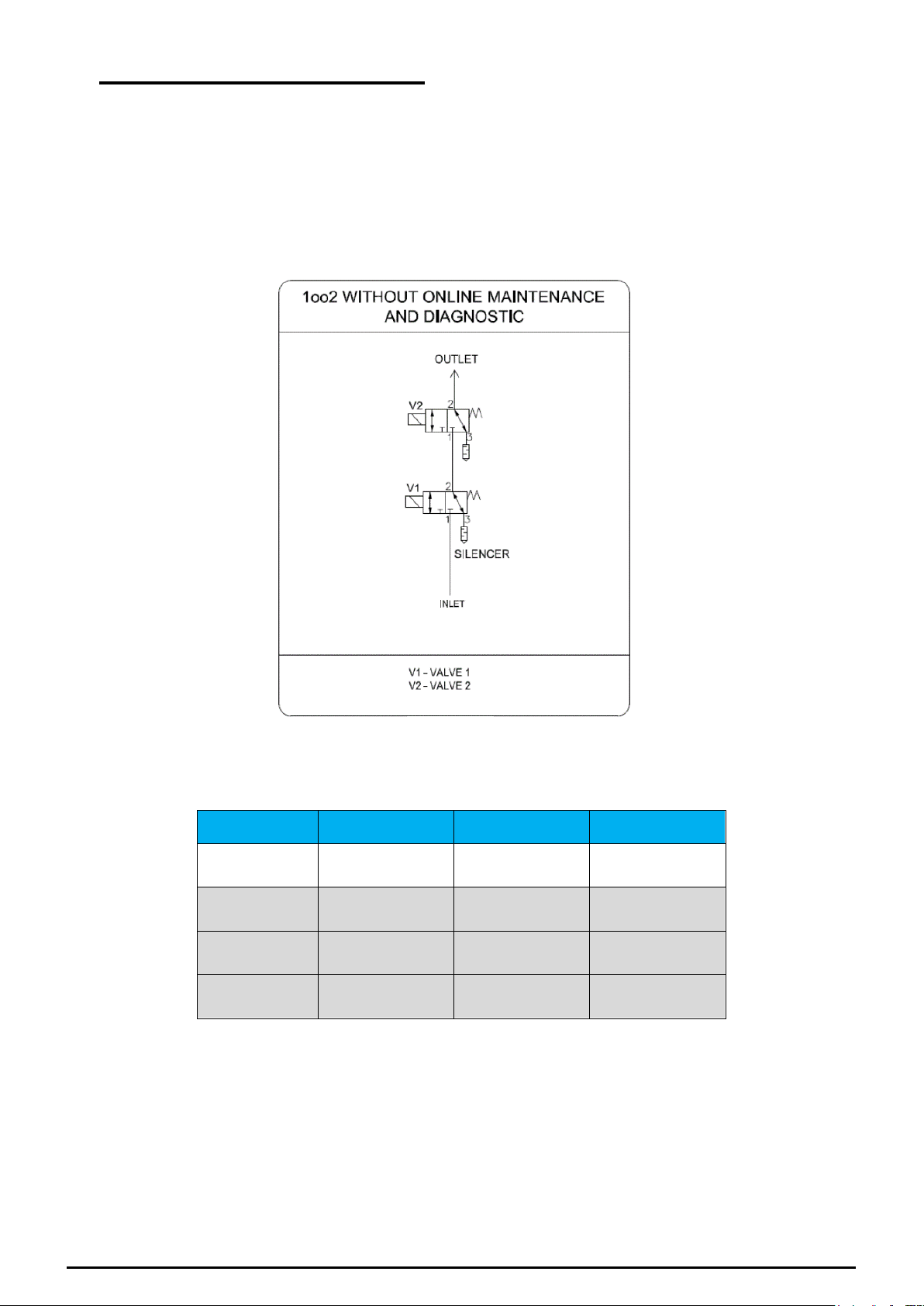
Figure 1
5.1 Modes of Operation
5.1.1 1oo2 without Online Maintenance & without Diagnostic
Figure 1 shows circuit diagram of 1oo2 without online maintenance & without diagnostic (safety state action). In
this condition, the ARCS is blocking the inlet air supply and venting the valve actuator (Normally closed
operation). This configuration is mostly used in safety applications since a loss of electrical or pneumatic energy
will result in the safe state of the actuator. V1 & V2 are solenoid operated valves. Both valves are energized then
only outlet will gets air supply. Online maintenance not applicable in this configuration.
The truth table for all possible device states is shown in Table 1.
Table 1
If the logic solver responds to a safety demand, it de-energizes SOV1 and SOV2 and causes the inlet air supply
to be blocked off and venting the block valve actuator.
5.1.2 1oo2 with common bypass & without Diagnostic
Figure 2 shows circuit diagram of 1oo2 with common bypass and without diagnostic (safety state action). In this
condition, the ARCS is blocking the inlet air supply and venting the valve actuator (Normally closed operation).
This configuration is mostly used in safety applications since a loss of electrical or pneumatic energy will result in
the safe state of the actuator. V1 & V2 are solenoid operated valves. Both valves are energized then only outlet
will gets air supply. B1 is manual operated bypass valve with LOTO protection. A, B and C are visual indicators,
Page 8 of 24
No. 57, Kundrathur Main Rd., Gerugambakkam, Chennai -6000128, India www.asco.com
IM-IND-536661-Rev AA
Page 9

A & B will show green when air is available and will show red when air is not available at particular valve zone.
State
Bypass Valve
in
Normal
V1
V2
Bypass
Visual
Indicator
A
Visual
Indicator
B
Visual
Indicator
C
Outlet
1
(Normal)
Both SOV's
Energized
Energized
Energized
Normal
Green
Green
Red
Air Supply
2
(Safe)
Both SOV's
De-Energized
De-
Energized
De-
Energized
Normal
Red
Red
Red
Vented
3
(Safe)
V1
De-Energized
only
De-
Energized
Energized
Normal
Red
Red
Red
Vented
4
(Safe)
V2
De-energized
Only
Energized
De-
Energized
Normal
Green
Red
Red
Vented
State
Bypass Valve
in
Bypass
V1
V2
Bypass
Visual
Indicator
A
Visual
Indicator
B
Visual
Indicator
C
Outlet
5
(Bypass)
Valve bypassed
for
repair
De-
Energized
De-
Energized
Bypass
Red
Red
Green
Air Supply
6
Illegal state
Energized
Energized
Bypass
Red
Red
Green
Air Supply
7
Illegal state
De-
Energized
Energized
Bypass
Red
Red
Green
Air Supply
8
Illegal state
Energized
De-
Energized
Bypass
Red
Red
Green
Air Supply
Figure 2
Table 2
Indicator C will be in red when bypass valve mode in normal.
Before switching to bypass mode, remove LOTO and lock pin from bypass valve and pull the knob downwards
and again put the lock pin and LOTO and make it secured. Bypass valve indicator will show green when bypass
mode is activated. To put in normal mode, do the above-mentioned process as reverse. Can do the repair of
SOV and Visual indicator after bypass mode is activated and without disturbing the outlet air supply.
The truth table for all possible device states is shown in Table 2.
• Highlighted in light gray is the state when the ARCS unit is in a legal mode other than the standard
running conditions.
• Dark gray indicates an illegal state.
Page 9 of 24
No. 57, Kundrathur Main Rd., Gerugambakkam, Chennai -6000128, India www.asco.com
IM-IND-536661-Rev AA
Page 10

If the logic solver responds to a safety demand, it de-energizes SOV1 and SOV2 and causes the inlet air supply
State
V1
V2
Outlet
1
(Normal)
Energized
Energized
Air Supply
2
(Normal)
Energized
De-Energized
Air Supply
3
(Normal)
De-Energized
Energized
Air Supply
4
(Safe)
De-Energized
De-Energized
Vented
Figure 3
to be blocked off and venting the block valve actuator.
5.1.3 2oo2 without Online Maintenance & without Diagnostic
Figure 3 shows circuit diagram of 2oo2 without online maintenance and diagnostic (safety state action). In this
condition, the ARCS is blocking the inlet air supply and venting the valve actuator (Normally closed operation).
This configuration is mostly used in availability applications since a loss of electrical or pneumatic energy of any
one valve also outlet will supply air to the actuator. V1 & V2 are solenoid operated valves. Online maintenance
not applicable in this configuration.
Page 10 of 24
No. 57, Kundrathur Main Rd., Gerugambakkam, Chennai -6000128, India www.asco.com
The truth table for all possible device states is shown in Table 3.
Table 3
If the logic solver responds to a safety demand, it de-energizes SOV1 and SOV2 and causes the inlet air supply
to be blocked off and venting the block valve actuator.
IM-IND-536661-Rev AA
Page 11

5.1.4 2oo2 without Online Maintenance & with Diagnostic
State
V1
V2
Visual Indicator A/
Pressure Switch P1
Visual Indicator B/
Pressure Switch P2
Outlet
1
(Normal)
Energized
Energized
Green
(Close)
Green
(Close)
Air Supply
2
(Normal)
Energized
De-Energized
Green
(Close)
Red
(Open)
Air Supply
3
(Normal)
De-Energized
Energized
Red
(Open)
Green
(Close)
Air Supply
4
(Safe)
De-Energized
De-Energized
Red
(Open)
Red
(Open)
Vented
Figure 4
Figure 4 shows circuit diagram of 2oo2 without online maintenance and with diagnostic (safety state action). In
this condition, the ARCS is blocking the inlet air supply and venting the valve actuator (Normally closed
operation). This configuration is mostly used in availability applications since a loss of electrical or pneumatic
energy of any one valve also outlet will supply air to the actuator. V1 & V2 are solenoid operated valves. A and B
are visual indicators, P1 and P2 are pressure switches. Indicators will show green when air is available and will
show red when air is not available at particular valve zone. Pressure switches will give signal of each valve zone
which is open or close. Online maintenance not applicable in this configuration.
The truth table for all possible device states is shown in Table 4
If the logic solver responds to a safety demand, it de-energizes SOV1 and SOV2 and causes the inlet air supply
to be blocked off and venting the block valve actuator.
Page 11 of 24
No. 57, Kundrathur Main Rd., Gerugambakkam, Chennai -6000128, India www.asco.com
Table 4
IM-IND-536661-Rev AA
Page 12

5.1.5 2oo2 with common bypass and with Diagnostic
Figure 5
Figure 5 shows circuit diagram of 2oo2 with common bypass and with diagnostic (safety state action). In this
condition, the ARCS is blocking the inlet air supply and venting the valve actuator (Normally closed operation).
This configuration is mostly used in availability applications since a loss of electrical or pneumatic energy of any
one valve also outlet will supply air to the actuator. V1 & V2 are solenoid operated valves. B1 is manual operated
bypass valve with LOTO protection. A, B and C are visual indicators, A & B will show green when air is available
and will show red when air is not available at particular valve zone. Indicator C will be in red when bypass valve
mode in normal. P1 and P2 are Pressure Switches, pressure switches will give signal of each of the valve zone
which is open or close.
Before switching to bypass mode, remove LOTO and lock pin from bypass valve and pull the knob downwards
and again put the lock pin and LOTO and make it secured. Bypass valve indicator will show green when bypass
mode is activated. Can do the repair of SOV, Visual indicator and pressure switches after bypass mode is
activated and without disturbing the outlet air supply.
To put in normal mode, do the above-mentioned process as reverse.
The truth table for all possible device states is shown in Table 5
Page 12 of 24
No. 57, Kundrathur Main Rd., Gerugambakkam, Chennai -6000128, India www.asco.com
IM-IND-536661-Rev AA
Page 13

Table 5
State
Bypass
valve in
Normal
V1
V2
Bypass
Visual
Indicator
A/
Pressure
Switch P1
Visual
Indicator
B/
Pressure
Switch
P2
Visual
Indicator
C
Outlet
1
(Normal)
Both SOV's
Energized
Energized
Energized
Normal
Green
(Close)
Green
(Close)
Red
Air
Supply
2
(Safe)
Both SOV's
De-
Energized
De-
Energized
De-
Energized
Normal
Red
(Open)
Red
(Open)
Red
Vented
3
(Normal)
V1
De-
Energized
only
De-
Energized
Energized
Normal
Red
(Open)
Green
(Close)
Red
Air
Supply
4
(Normal)
V2
De-
energized
Only
Energized
De-
Energized
Normal
Green
(Close)
Red
(Open)
Red
Air
Supply
State
Bypass
valve in
Bypass
V1
V2
Bypass
Visual
Indicator
A/
Pressure
Switch P1
Visual
Indicator
B/
Pressure
Switch
P2
Visual
Indicator
C
Outlet
5
(Bypass)
Valve
bypassed
for
repair
De-
Energized
De-
Energized
Bypass
Red
(Open)
Red
(Open)
Green
Air
Supply
6
Illegal state
Energized
Energized
Bypass
Red
(Open)
Red
(Open)
Green
Air
Supply
7
Illegal state
De-
Energized
Energized
Bypass
Red
(Open)
Red
(Open)
Green
Air
Supply
8
Illegal state
Energized
De-
Energized
Bypass
Red
(Open)
Red
(Open)
Green
Air
Supply
Page 13 of 24
No. 57, Kundrathur Main Rd., Gerugambakkam, Chennai -6000128, India www.asco.com
If the logic solver responds to a safety demand, it de-energizes SOV1 and SOV2 and causes the inlet air supply
to be blocked off and venting the block valve actuator.
5.1.6 2oo2 with individual isolation and with Diagnostic
Figure 6 shows circuit diagram of 2oo2 with individual isolation and with diagnostic (safety state action). In this
condition, the ARCS is blocking the inlet air supply and venting the valve actuator (Normally closed operation).
This configuration is mostly used in availability applications since a loss of electrical or pneumatic energy of any
one valve also outlet will supply air to the actuator. V1 & V2 are solenoid operated valves. I1 & I2 are manual
operated isolation valves with LOTO protection. A & B are visual indicators, P1 and P2 are pressure switches.
Indicators will show green when air is available and will show red when air is not available at particular valve
zone. Pressure switches will give signal of each valve zone which is open or close.
Before switching to isolation mode, remove LOTO and lock pin from isolation valve and pull the knob downwards
and again put the lock pin and LOTO and make it secured. Corresponding SOV, visual indicator and pressure
switch are isolated from the main line. Corresponding Indicator will show red when isolation valve is activated.
Can do maintenance of SOV, Indicator and pressure switch without disturbing outlet air supply.
To put in normal mode, do the above-mentioned process as reverse.
IM-IND-536661-Rev AA
Page 14

State
V1
V2
Visual Indicator A/
Pressure Switch P1
Visual Indicator B/
Pressure Switch P2
Outlet
1
(Normal)
Energized
Energized
Green
(Close)
Green
(Close)
Air Supply
2
(Normal)
Energized
De-Energized
Green
(Close)
Red
(Open)
Air Supply
3
(Normal)
De-Energized
Energized
Red
(Open)
Green
(Close)
Air Supply
4
(Safe)
De-Energized
De-Energized
Red
(Open)
Red
(Open)
Vented
Figure 6
The truth table for all possible device states is shown in Table 6
Table 6
If the logic solver responds to a safety demand, it de-energizes SOV1 and SOV2 and causes the inlet air supply
to be blocked off and venting the block valve actuator.
5.1.7 2oo3 without Online Maintenance & without Diagnostic
Figure 7 shows circuit diagram of 2oo3 without online maintenance and diagnostic (safety state action). In this
condition, the ARCS is blocking the inlet air supply and venting the valve actuator (Normally closed operation).
This configuration is mostly used in safety and availability applications. V1, V2, V3 & V4 are solenoid operated
valves. Online maintenance not applicable in this configuration.
Page 14 of 24
No. 57, Kundrathur Main Rd., Gerugambakkam, Chennai -6000128, India www.asco.com
IM-IND-536661-Rev AA
Page 15

The truth table for all possible device states is shown in Table 7
Figure 7
Page 15 of 24
No. 57, Kundrathur Main Rd., Gerugambakkam, Chennai -6000128, India www.asco.com
IM-IND-536661-Rev AA
Page 16

Table 7
State
Channel - 1
Channel - 2
Channel - 3
Outlet
V1
V2
V3
V4
1
Energized
De-Energized
De-Energized
De-Energized
Vented
2
Energized
Energized
De-Energized
De-Energized
Vented
3
Energized
Energized
Energized
De-Energized
Air Supply
4
Energized
Energized
Energized
Energized
Air Supply
5
De-Energized
Energized
De-Energized
De-Energized
Vented
6
De-Energized
Energized
Energized
De-Energized
Vented
7
De-Energized
Energized
Energized
Energized
Air Supply
8
De-Energized
Energized
De-Energized
Energized
Air Supply
9
De-Energized
De-Energized
Energized
De-Energized
Vented
10
De-Energized
De-Energized
Energized
Energized
Vented
11
Energized
De-Energized
Energized
Energized
Air Supply
12
Energized
De-Energized
Energized
De-Energized
Air Supply
13
De-Energized
De-Energized
De-Energized
Energized
Vented
14
Energized
De-Energized
De-Energized
Energized
Air Supply
15
Energized
Energized
De-Energized
Energized
Air Supply
16
De-Energized
De-Energized
De-Energized
De-Energized
Vented
If the logic solver responds to a safety demand, it de-energizes SOV1, SOV2, SOV3 and SOV4 and causes the
inlet air supply to be blocked off and venting the block valve actuator.
5.1.8 2oo3 without Online Maintenance & with Diagnostic
Figure 8 shows circuit diagram of 2oo3 without online maintenance, with diagnostic (safety state action). In this
condition, the ARCS is blocking the inlet air supply and venting the valve actuator (Normally closed operation).
This configuration is mostly used in safety and availability applications. V1, V2, V3 & V4 are solenoid operated
valves. A, B, C and D are visual indicators, P1, P2, P3 and P4 are pressure switches. Indicators will show green
when air is available and will show red when air is not available at particular valve zone. Pressure switches will
give signal of each valve zone which is open or close. Online maintenance not applicable in this configuration.
Page 16 of 24
No. 57, Kundrathur Main Rd., Gerugambakkam, Chennai -6000128, India www.asco.com
IM-IND-536661-Rev AA
Page 17

The truth table for all possible device states is shown in Table 8.
Figure 8
Page 17 of 24
No. 57, Kundrathur Main Rd., Gerugambakkam, Chennai -6000128, India www.asco.com
IM-IND-536661-Rev AA
Page 18

Table 8
State
Channel -1
Channel -
2
Channel -
3
Visual
Indicator
A/
Pressure
Switch
P1
Visual
Indicator
D/
Pressure
Switch
P4
Visual
Indicator
B/
Pressure
Switch
P2
Visual
Indicator
C/
Pressure
Switch
P3
Outlet
V1
V4
V2
V3
1
Energized
De-
Energized
De-
Energized
De-
Energized
Green
(Close)
Red
(Open)
Red
(Open)
Red
(Open)
Vented
2
Energized
De-
Energized
Energized
De-
Energized
Green
(Close)
Red
(Open)
Green
(Close)
Red
(Open)
Vented
3
Energized
De-
Energized
Energized
Energized
Green
(Close)
Red
(Open)
Green
(Close)
Green
(Close)
Air
Supply
4
Energized
Energized
Energized
Energized
Green
(Close)
Green
(Close)
Green
(Close)
Green
(Close)
Air
Supply
5
De-
Energized
De-
Energized
Energized
De-
Energized
Red
(Open)
Red
(Open)
Green
(Close)
Red
(Open)
Vented
6
De-
Energized
De-
Energized
Energized
Energized
Red
(Open)
Red
(Open)
Green
(Close)
Green
(Close)
Air
Supply
7
De-
Energized
Energized
Energized
Energized
Red
(Open)
Green
(Close)
Green
(Close)
Green
(Close)
Air
Supply
8
De-
Energized
Energized
Energized
De-
Energized
Red
(Open)
Green
(Close)
Green
(Close)
Red
(Open)
Air
Supply
9
De-
Energized
De-
Energized
De-
Energized
Energized
Red
(Open)
Red
(Open)
Red
(Open)
Red*
(Open)
Vented
10
De-
Energized
Energized
De-
Energized
Energized
Red
(Open)
Red*
(Open)
Red
(Open)
Red*
(Open)
Vented
11
Energized
Energized
De-
Energized
Energized
Green
(Close)
Red*
(Open)
Red
(Open)
Green
(Close)
Air
Supply
12
Energized
De-
Energized
De-
Energized
Energized
Green
(Close)
Red
(Open)
Red
(Open)
Green
(Close)
Air
Supply
13
De-
Energized
Energized
De-
Energized
De-
Energized
Red
(Open)
Red*
(Open)
Red
(Open)
Red
(Open)
Vented
14
Energized
Energized
De-
Energized
De-
Energized
Green
(Close)
Red*
(Open)
Red
(Open)
Red
(Open)
Vented
15
Energized
Energized
Energized
De-
Energized
Green
(Close)
Green
(Close)
Green
(Close)
Red
(Open)
Air
Supply
16
De-
Energized
De-
Energized
De-
Energized
De-
Energized
Red
(Open)
Red
(Open)
Red
(Open)
Red
(Open)
Vented
* Indicators show Red which is "False" state, due to unavailability of Pneumatic air since the valves are
connected in series (Refer Circuit).
If the logic solver responds to a safety demand, it de-energizes SOV1, SOV2, SOV3 and SOV4 and causes the
inlet air supply to be blocked off and venting the block valve actuator.
5.1.9 2oo3 with individual isolation and with Diagnostic
Figure 9 shows circuit diagram of 2oo3 with individual isolation and with diagnostic (safety state action). In this
condition, the ARCS is blocking the inlet air supply and venting the valve actuator (Normally closed operation).
This configuration is mostly used in safety and availability applications. V1, V2, V3 & V4 are solenoid operated
valves. I1, I2, I3 & I4 are manual operated isolation valve with LOTO protection. A, B, C & D are visual indicators,
P1, P2, P3 and P4 are pressure switches. Indicators will show green when air is available and will show red
when air is not available at particular valve zone. Pressure switches will give signal of each valve zone which is
open or close. Before switching to isolation mode, remove LOTO and lock pin from isolation valve and pull the
knob downwards and again put the lock pin and LOTO and make it secured. Corresponding SOV, visual
indicator and pressure switch are isolated from the main line. Corresponding Indicator will show red when
isolation valve is activated. Can do maintenance of SOV, Indicator and pressure switch without disturbing outlet
air supply. To put in normal mode, do the above-mentioned process as reverse.
Page 18 of 24
No. 57, Kundrathur Main Rd., Gerugambakkam, Chennai -6000128, India www.asco.com
IM-IND-536661-Rev AA
Page 19

Figure 9
The truth table for all possible device states is shown in Table 9.
Page 19 of 24
No. 57, Kundrathur Main Rd., Gerugambakkam, Chennai -6000128, India www.asco.com
IM-IND-536661-Rev AA
Page 20

State
Channel -1
Channel -
2
Channel -
3
Visual
Indicator
A/
Pressure
Switch P1
Visual
Indicator
D/
Pressure
Switch P4
Visual
Indicator
B/
Pressure
Switch P2
Visual
Indicator
C/
Pressure
Switch P3
Outlet
V1
V4
V2
V3
1
Energized
De-
Energized
De-
Energized
De-
Energized
Green
(Close)
Red
(Open)
Red
(Open)
Red
(Open)
Vented
2
Energized
De-
Energized
Energized
De-
Energized
Green
(Close)
Red
(Open)
Green
(Close)
Red
(Open)
Vented
3
Energized
De-
Energized
Energized
Energized
Green
(Close)
Red
(Open)
Green
(Close)
Green
(Close)
Air
Supply
4
Energized
Energized
Energized
Energized
Green
(Close)
Green
(Close)
Green
(Close)
Green
(Close)
Air
Supply
5
De-
Energized
De-
Energized
Energized
De-
Energized
Red
(Open)
Red
(Open)
Green
(Close)
Red
(Open)
Vented
6
De-
Energized
De-
Energized
Energized
Energized
Red
(Open)
Red
(Open)
Green
(Close)
Green
(Close)
Air
Supply
7
De-
Energized
Energized
Energized
Energized
Red
(Open)
Green
(Close)
Green
(Close)
Green
(Close)
Air
Supply
8
De-
Energized
Energized
Energized
De-
Energized
Red
(Open)
Green
(Close)
Green
(Close)
Red
(Open)
Air
Supply
9
De-
Energized
De-
Energized
De-
Energized
Energized
Red
(Open)
Red
(Open)
Red
(Open)
Red*
(Open)
Vented
10
De-
Energized
Energized
De-
Energized
Energized
Red
(Open)
Red*
(Open)
Red
(Open)
Red*
(Open)
Vented
11
Energized
Energized
De-
Energized
Energized
Green
(Close)
Red*
(Open)
Red
(Open)
Green
(Close)
Air
Supply
12
Energized
De-
Energized
De-
Energized
Energized
Green
(Close)
Red
(Open)
Red
(Open)
Green
(Close)
Air
Supply
13
De-
Energized
Energized
De-
Energized
De-
Energized
Red
(Open)
Red*
(Open)
Red
(Open)
Red
(Open)
Vented
14
Energized
Energized
De-
Energized
De-
Energized
Green
(Close)
Red*
(Open)
Red
(Open)
Red
(Open)
Vented
15
Energized
Energized
Energized
De-
Energized
Green
(Close)
Green
(Close)
Green
(Close)
Red
(Open)
Air
Supply
16
De-
Energized
De-
Energized
De-
Energized
De-
Energized
Red
(Open)
Red
(Open)
Red
(Open)
Red
(Open)
Vented
Table 9
* Indicators show Red which is "False" state, due to unavailability of Pneumatic air since the valves are
connected in series (Refer Circuit).
If the logic solver responds to a safety demand, it de-energizes SOV1, SOV2, SOV3 and SOV4 and causes the
inlet air supply to be blocked off and venting the block valve actuator.
5.1.10 2oo3 with common bypass and with Diagnostic
Figure 10 shows circuit diagram of 2oo3 with common bypass and with diagnostic (safety state action). In this
condition, the ARCS is blocking the inlet air supply and venting the valve actuator (Normally closed operation).
This configuration is mostly used in safety and availability applications. V1, V2, V3 & V4 are solenoid operated
valves. B1 is manual operated bypass valve with LOTO protection. A, B, C, D and E are visual indicators, A, B, C
& D will show green when air is available and will show red when air is not available at particular valve zone.
Page 20 of 24
No. 57, Kundrathur Main Rd., Gerugambakkam, Chennai -6000128, India www.asco.com
IM-IND-536661-Rev AA
Page 21

Indicator E will be in red when bypass valve mode in normal. P1, P2, P3 and P4 are Pressure Switches,
Figure 10
pressure switches will give signal of each of the valve zone which is open or close.
Before switching to bypass mode, remove LOTO and lock pin from bypass valve and pull the knob downwards
and again put the lock pin and LOTO and make it secured. Bypass valve indicator E will show green when
bypass mode is activated. Can do the repair of SOV, Visual indicator and pressure switches after bypass mode
is activated and without disturbing the outlet air supply.
To put in normal mode, do the above-mentioned process as reverse.
Page 21 of 24
No. 57, Kundrathur Main Rd., Gerugambakkam, Chennai -6000128, India www.asco.com
The truth table for all possible device states is shown in Table 10.
IM-IND-536661-Rev AA
Page 22

Bypass valve in Normal Mode
State
Channel -1
Channel -
2
Channel -
3
Visual
Indicator
A/
Pressure
Switch
P1
Visual
Indicator
D/
Pressure
Switch
P4
Visual
Indicator
B/
Pressure
Switch
P2
Visual
Indicator
C/
Pressure
Switch
P3
Visual
Indicator
E
Outlet
V1
V4
V2
V3
1
Energized
De-
Energized
De-
Energized
De-
Energized
Green
(Close)
Red
(Open)
Red
(Open)
Red
(Open)
Red
Vented
2
Energized
De-
Energized
Energized
De-
Energized
Green
(Close)
Red
(Open)
Green
(Close)
Red
(Open)
Red
Vented
3
Energized
De-
Energized
Energized
Energized
Green
(Close)
Red
(Open)
Green
(Close)
Green
(Close)
Red
Air Supply
4
Energized
Energized
Energized
Energized
Green
(Close)
Green
(Close)
Green
(Close)
Green
(Close)
Red
Air Supply
5
De-
Energized
De-
Energized
Energized
De-
Energized
Red
(Open)
Red
(Open)
Green
(Close)
Red
(Open)
Red
Vented
6
De-
Energized
De-
Energized
Energized
Energized
Red
(Open)
Red
(Open)
Green
(Close)
Green
(Close)
Red
Air Supply
7
De-
Energized
Energized
Energized
Energized
Red
(Open)
Green
(Close)
Green
(Close)
Green
(Close)
Red
Air Supply
8
De-
Energized
Energized
Energized
De-
Energized
Red
(Open)
Green
(Close)
Green
(Close)
Red
(Open)
Red
Air Supply
9
De-
Energized
De-
Energized
De-
Energized
Energized
Red
(Open)
Red
(Open)
Red
(Open)
Red*
(Open)
Red
Vented
10
De-
Energized
Energized
De-
Energized
Energized
Red
(Open)
Red*
(Open)
Red
(Open)
Red*
(Open)
Red
Vented
11
Energized
Energized
De-
Energized
Energized
Green
(Close)
Red*
(Open)
Red
(Open)
Green
(Close)
Red
Air Supply
12
Energized
De-
Energized
De-
Energized
Energized
Green
(Close)
Red
(Open)
Red
(Open)
Green
(Close)
Red
Air Supply
13
De-
Energized
Energized
De-
Energized
De-
Energized
Red
(Open)
Red*
(Open)
Red
(Open)
Red
(Open)
Red
Vented
14
Energized
Energized
De-
Energized
De-
Energized
Green
(Close)
Red*
(Open)
Red
(Open)
Red
(Open)
Red
Vented
15
Energized
Energized
Energized
De-
Energized
Green
(Close)
Green
(Close)
Green
(Close)
Red
(Open)
Red
Air Supply
16
De-
Energized
De-
Energized
De-
Energized
De-
Energized
Red
(Open)
Red
(Open)
Red
(Open)
Red
(Open)
Red
Vented
State
Bypass
valve in
bypass
Channel -1
Channel -
2
Channel -
3
Visual
Indicator
A/
Pressure
Switch
P1
Visual
Indicator
D/
Pressure
Switch
P4
Visual
Indicator
B/
Pressure
Switch
P2
Visual
Indicator
C/
Pressure
Switch
P3
Visual
Indicator
E
Outlet
V1
V4
V2
V3
1
(Bypass)
Valve
bypassed
for
repair
De-
Energized
De-
Energized
De-
Energized
De-
Energized
Red
(Open)
Red
(Open)
Red
(Open)
Red
(Open)
Green
Air
Supply
Table 10
* Indicators show Red which is "False" state, due to unavailability of Pneumatic air, since the valves are connected in
series (Refer Circuit).
Bypass valve in bypass Mode
Remaining states are illegal state when bypass mode is activated.
5.2 Operator Interface Options
The ARCS (141 series) is available with various interface and visual indication options. These options provide
local indication and feedback for plant personnel. There are several constraints related to these options.
• Any operator interface shall be implemented in a manner that has a predictable effect on the ARCS and
does not interfere with its safety function.
• Field modifications shall not be made to the internal wiring or pneumatic connections of the ARCS.
Page 22 of 24
No. 57, Kundrathur Main Rd., Gerugambakkam, Chennai -6000128, India www.asco.com
IM-IND-536661-Rev AA
Page 23

5.3 ADT - Optional
ARCS (141 series) has redundant architecture which is sufficient to meet safety integrity level. However, ARCS
facilitate Automated diagnostic testing for individual solenoid valve in 2oo2 and 2oo3 configurations. Pressure or
Proximity switches shall be provided as optional for individual solenoid valves which facilitates online testing of
solenoid valves through safety systems or DCS.
In addition to the static detection of the system state and to enable the logic-solver to verify correct system state
transition, the sensor information is used to implement a safety-critical test of the ARCS function.
For functional testing, all solenoids are brought on-line depending on redundant configuration. Each solenoid is
then de-energized individually with pressure switch confirmation of successful venting. No bypass/isolation is
required for functional testing. This means that the system is sequenced through the truth table and the correct
assertion of these states is verified by reading the pressure switch transition. The safe state can be achieved at
any time during the function test by de-energizing the digital outputs on the safety rated logic solver.
The functional testing is performed to detect potential undetected dangerous component failure within the device
such as:
• SOV is stuck in energized position
• Pressure switch stuck in open or closed position
The position of the bypass / isolation valve is safety critical, are provided with LOTO protection which can be
secured with a lock. The bypass / isolation valve should be locked position at any state normal operation or
Bypass / isolation.
Any failure detected by the ADT shall be annunciated by the safety rated logic solver.
5.3.1 State Verification Test
The correct state of all valves shall be verified and compared against the commanded state. The state table in
section 5.1 of this manual can be used as a guide. This verification shall be performed periodically with a cycle
time of ½ of the process safety time or less.
If any illegal states are detected, they shall be immediately annunciated. These states are excluded by design
and the root cause for these faults cannot be determined or be contributed to a specific component. The ARCS
shall be repaired within 72 hours.
5.4 Repair and replacement
Repair procedures in I&M Number 536985 must be followed.
5.5 ASCO Notification
Any failures that are detected and that compromise functional safety should be reported to ASCO
Please contact ASCO Technical Support.
6 Status of the document
6.1 Releases
Version: V0
Revision: R0
Release status: ECN 290115 Released on December 12, 2018
Page 23 of 24
No. 57, Kundrathur Main Rd., Gerugambakkam, Chennai -6000128, India www.asco.com
IM-IND-536661-Rev AA
Page 24

Appendix A – SIS Checklist
#
Activity
Result
Verified
By
Date
Design
Target Safety Integrity Level and PFDavg determined
Correct valve mode chosen (NC)
Design decision documented
Electrical compatibility and suitability verified
Pneumatic compatibility and suitability verified
SIS logic solver requirements for valve tests defined and
documented
Line monitoring requirements for SIS logic solver connection
determined
Routing of electric and pneumatic connections determined
Design formally reviewed, and suitability formally assessed
Implementation
Physical location appropriate
Electrical connections appropriate and according to applicable
codes
Pneumatic connections appropriate and according to applicable
codes
SIS logic solver state verification test implemented
SIS logic solver valve actuation test implemented
Maintenance instructions for proof test released (Optional)
Verification and test plan released
Implementation formally reviewed, and suitability formally
assessed
Verification and Testing
Electrical connections verified and tested
Pneumatic connection verified and tested
SIS logic solver state verification test verified
SIS logic solver valve actuation test verified
Safety loop function verified
Safety loop timing measured
Bypass function tested
Verification and test results formally reviewed, and suitability
formally assessed
Maintenance
Tubing blockage / partial blockage tested
Enclosure vent inspected
Electrical connection inspected
Bypass function and pressure sensors tested
Safety loop function tested
The following checklist may be used as a guide to employ the RCS device in a safety critical SIF compliant to
IEC61508.tivit
y
Page 24 of 24
No. 57, Kundrathur Main Rd., Gerugambakkam, Chennai -6000128, India www.asco.com
IM-IND-536661-Rev AA
 Loading...