

Page 1
I&M No. V_9512_R9
Operation & Maintenance Guide
THIS DOCUMENT CONTROLLED BY
RCS Ex CERTIFICATION
ASCO Valves
©
ASCO Valve, Inc. 50 Hanover Road, Florham Park, New Jersey 07932 www.ascovalve.com Page 1 of 18
®
E258615 - 09/2015 All Rights Reserved. I&M No. V_9512_R9
Page 2

Operation & Maintenance Guide
Redundant Control System
Table of Contents
Product Description 3
ATEX Environmental Ratings 4
General Specications 4
Nameplate Information (ATEX Versions Only) 5
Section 1-Normally Closed 7
1. General Operation 7
2. Testing and Maintenance 9
Section 2-Normally Open 10
1. General Operation 10
2. Testing and Maintenance 11
Section 3-Double Acting 12
1. General Operation 12
2. Testing and Maintenance 13
Section 4 14
1. Functional Test Certication 14
2. Spare Parts 14
3. Packaging 14
4. Limited Warranty 14
5. Tools Required for Routine Service 14
RCS Base Unit Wiring Diagram (A) 15
RCS Base Unit with PLC Wiring Diagram (B) 16
RCS N.C. Piping Diagrams 17
RCS N.O. Piping Diagrams 18
Page 2 of 18 I&M No. V_9512_R9
©ASCO Valve, Inc. 50 Hanover Road, Florham Park, New Jersey 07932 www.ascovalve.com
Page 3

Documentation Conventions
This guide uses the following typographic conventions:
EXAMPLE
NOTE
Notes containing supplementary information.
This symbol precedes information about
potential equipment damage.
This symbol precedes information about
potential personnel hazards.
Description
User Experience Prerequisites
To effectively use the Pneumatic RCS, users should have some
experience with pneumatic systems.
Warnings!
READ THIS ENTIRE MANUAL AND ALL RELATED
PUBLICATIONS PERTAINING TO THE WORK TO BE
PERFORMED BEFORE INSTALLING, OPERATING OR
SERVICING THIS EQUIPMENT.
• Follow all appropriate safety codes and standards.
• Failure to follow instructions may result in personal injury
and/or property damage.
• Use extreme caution when working around power-input
cables. These cables may have potentially lethal or dangerous
voltages.
• Prior to energizing the equipment, have qualied personnel
verify all wiring and connections against vendor drawings.
Incorrect wiring and/or connections can result in equipment
damage or serious system failure. If you have questions or
need more information on installing and operating ASCO
equipment, contact ASCO.
OPERATIONAL ATMOSPHERE CONSIDERATIONS:
The ATEX version of the Redundant Control System (hereafter
referred to as RCS) is designed in accordance with Annex II of
the European Directive 94/EC and European standards EN 60079-
0, EN 60079-1, EN 60079-7, and EN 600079-18. Classication : II
2G Ex d e mb IIC Gb IP-56.
MODELS COVERED BY ATEX APPROVAL:
ATEX Approval applies to RCS products having an ASCO Part
Number beginning with “5RC”, and that contain any combination
of the following features:
Manifold Architecture: Normally Closed, Normally Open, or
Double Acting.
Enclosure Material: 304 SS, 316 SS
System Voltage: 12 VDC, 24 VDC, 48 VDC, 120 VDC, 110/50-
120/60, 230/50-240/50
Operational Mode: Energized to trip or De-energized to trip
Optional Features: Common Alarm, Local Initiation of SOV test,
Local Initiation of Partial Stroke test, Bypass indication, Silver
Contact for relay logic or Lever type bypass switch.
User dened lights and push buttons: Any combination of standard
catalog lights and push buttons.
Options not covered by ATEX Approval:
• RCS products having an ASCO Part Number beginning with “5RC”
that include Local Manual Reset or a Composite Enclosure
• RCS units containing a PLC
PRODUCT DESCRIPTION
The RCS is a two-out-of-two (2oo2) or one-out-of-one hot standby
(1oo1 HS) voting, solenoid-operated valve system designed for
use as a component in safety instrumented systems. It functions
as a redundant pneumatic tripping device to control the pilot air
signal to a process valve actuator. The RCS uses 2oo2 or 1oo1
HS voting solenoids to enhance the reliability of the circuit. The
RCS consists of two electrically actuated solenoid valves (SOV1,
SOV2) and a pneumatically operated (Manually Controlled) bypass
valve, and three pressure switches. The pressure switches provide
solenoid state feedback and are used during on-line testing of the
RCS unit. The bypass valve allows for maintenance of the solenoid
valves without having to shut down the process valve. The use of
the Maintenance Bypass Valve is not required for functional testing
of the RCS unit. The RCS is available as a base unit (5R) and base
unit with on-board PLC (5L). The 5L unit with on-board PLC is
programmed with the logic required for proper operation. The type
of operation (2oo2 NC, 2oo2 NO, 2oo2 DA, 1oo1HS NC, 1oo1HS
NO) must be specied by the customer at the time of order. During
normal operation of a 5L construction power is routed through the
PLC to SOV1 and SOV2. Pressure switches (PS1, PS2 and PS3)
are monitored by the PLC. In the event of a PLC failure, SOV1 and
SOV2 will be connected directly to the Diagnostic Control System
(hereafter referred to as DCS) output, allowing the DCS to have
supervisory control of SOV1 and SOV2. Normal operation of the
processed valve unit will not be effected during this event. The RCS
unit will continue to function with restricted capabilities.
Under normal operating conditions:
The RCS allows for periodic testing of the solenoids by cycling one
solenoid valve and then the other either manually or automatically
therefore attaining the desired safety availability. This testing is
performed online without the need for bypassing of the safety
action and without interruption of the process.
For all constructions, three pressure switches are included to
provide indication of each solenoid-operated valve and bypass valve
position.
Normally Closed Construction: the RCS supplies air to the
process valve actuator through the “Process” port when energized.
Page 3 of 18 I&M No. V_9512_R9
©ASCO Valve, Inc. 50 Hanover Road, Florham Park, New Jersey 07932 www.ascovalve.com
Normally Open Construction: the RCS blocks the incoming
pneumatic signal and connects the “Process” port to the “Exhaust”
port when energized.
Double Acting Construction: the incoming pneumatic control
signal passes through the RCS to one side (C2) of the process valve
actuator while the other side (C1) of the process valve actuator
is vented through the RCS when energized. The 1oo1 HS mode
cannot be used with the double acting construction.
When a trip occurs:
Normally Closed Construction: the RCS blocks the incoming
pneumatic signal and connects the “Process” port to the “Exhaust”
port. This vents the air signal from the process valve actuator and
allows the actuator return spring to move the process to its failsafe position.
Normally Open Construction: the RCS supplies air to the process
valve actuator through the “Process” port. This allows the actuator
to move the process to its fail-safe position.
Double Acting Construction: (C2) of the process valve actuator is
vented through the RCS while the pneumatic control signal is applied
to (C1) of the process valve actuator. This causes the process valve
actuator to move from its normal operating position to its fail-safe
position.
HARDWARE
For proper operation, a pneumatic pressure of 3-150 PSI must be
supplied to the RCS [process connection] while a pressure of 40-150
PSI must be supplied to the [pilot connection]. It is housed in a 20”
x 16” x 8” enclosure. The primary components include:
• Hard anodized aluminum manifold body
• Two low power solenoid-operated ISO-3 valves
• A key-actuated bypass valve.
• Three pressure switches (ATEX rated Ex d IIC).
• An electrical terminal block for wiring termination (ATEX
rated Ex e IIC)
• Associated wiring.
• An on-board digital processor (RCS-L only)
Page 4
3
-150 PSI
must
pressure
is
components
valves
(meets
A
key
-actuated bypass
valve.
Three p
ressure
switches
(meets UL Class I, Div. 2 and
ATEX rated Ex
d
IIC)
.
An electrical terminal block for wiring
termination
(ATEX rated Ex e
II)
Associated
wiring.
An
on
-board digital processor
(RCS-L only).
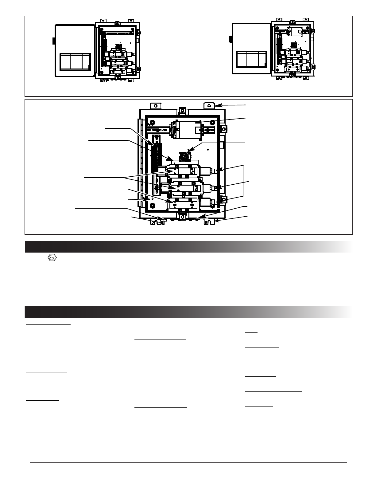
RCS-5R
eld wiring termination block
RCS-5L With Onboard PLC
Figure 1. General Appreance of the RCS
mounting brackets (2 on top)
on-board digital processor (RCS-L only)
pneumatic manifold
solenoid valves (2)
bypass valve
internal grounding/earthing connection
breather/vent
external grounding/earthing connection
Figure 2. RCS Components (Normally Closed shown)
ATEX ENVIRONMENTAL RATINGS
CE 0344 II 2G
Ex d e mb IIC T* Gb
• Ex : Explosion Protection Marking
• II: Equipment Group Other than Mines
• 2G: Category 2; Gas Atmosphere
• Ex : Explosion Protected
• d : Flameproof Protection Method
GENERAL SPECIFICATIONS
Solenoid Operator:
12, 24, 48 or 120 Volt DC Low Power,
Class F coil-1.4 watts and 1.7 watts
(1.7 watts does not apply to ATEX
versions)
120/60-110/50 or 230/50-240/50 AC
10.1 Watts
Pneumatic Valve:
ISO-3; 5/2 air-spring valve; solenoid
operated/Requires external pilot air
supply.
Bypass Valve:
ISO-3; 5/2 air-spring valve; manually
operated/Requires external pilot air
supply.
Manifold:
3- station ISO base; unique pneumatic
circuit design
• e : Increased Safety Protection Method
• mb : Encapsulation safety method (solenoid only)
• IIC : Atmosphere Group: Acetylene & Hydrogen
• *T180°C : Temperature Class 180°C-120/60-110/50 or 230/50-240/50 Applications
• *T6 : Temperature Class 85°C-12/DC, 24/DC, 48/DC or 120/DC Applications
• Gb : Equipment Protection level (“High” Level)
Pressure Switches:
3 each (ATEX rated Ex II 2G D Ex IIC T6)
Pressure Switch Type:
SPDT switches, hermetically sealed,
Anodized Aluminum
Switch Contact Rating:
Gold contacts (std) 1 amp suppressed
resistive load; .5 amps inductive load @
28 VDC.
Silver contacts (opt) 5 amps suppressed
resistive load; 3 amps inductive load @ 28
VDC.
Connection & Setting:
¼” NPTF; 3 psi increasing/ 1 psi decreasing;
non-adjustable.
Electrical:
Digital Processor (PLC):
RCS-L only, 14 inputs, 10 outputs
manually actuated bypass valve
pressure switches (3)
pneumatic connections
mounting brackets (2 on bottom)
Pneumatic Connections:
Pilot:
1/8” NPTF
Pilot Pressure:
40-150 psi
Inlet & Process:
1/2” NPTF
Exhaust Port:
1/2” NPTF
Process Pressure Range:
3 psi to 150 psi
Air Quality:
Instrument air per ANSI/ISA 7.0.01-1996
Particle size ≤ 40 microns.
Materials:
Enclosure:
Stainless Steel (304 SS, 316SS) or Fiberglass
(Fiberglass does not apply to ATEX versions)
Page 4 of 18 I&M No. V_9512_R9
©ASCO Valve, Inc. 50 Hanover Road, Florham Park, New Jersey 07932 www.ascovalve.com
Page 5

Size:
24”x 16”x 8”
Weight:
Approximately 75 lbs.
Mounting Panel
Painted Steel
Manifold:
Anodized aluminum.
Valves:
Body – Die-cast Aluminum alloy, SealingNitrile (NBR) and Polyurethane (PUR),
Solenoid Coil:
Epoxy encapsulated.
Pressure Switches:
316 Stainless Steel Wetted Surfaces
Environmental:
Ambient temperature range:
Consult panel nameplate to verify.
• RCS-R = -40°F to 140°F (-40°C to 60°C)
• RCS-R with local manual reset option
= -4°F to 140°F (-20°C to 60°C)
• RCS-L = -4°F to 131°F (-20°C to 55°C)
Approvals:
Exida
Certied SIL 3 capable (Standard
Normally Open and Normally Closed
constructions, see SIL certicate for
special constructions).
Spool and Stainless Steel.
NAMEPLATE INFORMATION (ATEX VERSIONS ONLY)
name of manufacturer
CE marking and number of
notied body responsible for
quality system (CE 0344)
ambient temperature rating
certicate number
serial number
including date code
120/60 - 110/50 or 230/50 - 240/50 Volt AC Applications
name of manufacturer
CE marking and number of
notied body responsible for
quality system (CE 0344)
™
ENCLOSURE TYPE 4, 4X, IP-66
Ex d e mb IIC T180°C Gb
Tamb -40°C to +60°C
ITS 07ATEX15746
MAX. AMBIENT TEMP
MODEL NO.
SERIAL NO./DATE
FLORHAM PARK, NEW JERSEY, USA
™
ENCLOSURE TYPE 4, 4X, IP-66
explosion protection marking
equipment group II category 2
type of explosive atmosphere
G=gas, vapor or mist
POWER MAX.
VOLTAGE AIR.
electrical parameters
INLET (PSI) AIR.
PILOT (PSI)
address of manufacturer
explosion protection marking
equipment group II category 2
type of explosive atmosphere
G=gas, vapor or mist
temperature T code T6=85°C/185°F
12/DC, 24/DC, 48/DC or 120/DC
applications
ambient temperature rating
certicate number
serial number
including date code
Page 5 of 18 I&M No. V_9512_R9
©ASCO Valve, Inc. 50 Hanover Road, Florham Park, New Jersey 07932 www.ascovalve.com
Ex d e mb IIC T6 Gb
Tamb -40°C to +60°C
ITS 07ATEX15746
POWER MAX.
MAX. AMBIENT TEMP
MODEL NO.
SERIAL NO./DATE
FLORHAM PARK, NEW JERSEY, USA
VOLTAGE AIR.
INLET (PSI) AIR.
PILOT (PSI)
12, 24, 48 or 120 Volt DC Applications
electrical parameters
address of manufacturer
Page 6

INSTALLATION
This section provides the information needed to install the RCS.
Unpacking:
Upon receipt of the RCS, unpack it carefully and visually check
for damage. The packing list shows the complete model number and
describes the features of the unit.
1. If the unit is damaged, immediately contact ASCO.
2. If everything is in order, proceed to the instructions in the
following sections.
Mounting Location Considerations:
The RCS is designed to be eld mounted near the process valve
to be actuated. The following factors should be considered when
selecting a mounting location:
• Accessibility: Allow ample space for door operation, and for
wiring and tubing runs.
• Temperature: Consider the amount of heat generated by equipment
in the mounting area. The RCS is intended for operation in ambient
temperatures from - 40°C to 60°C (RCS-R), -20°C to 60°C (RCS-R
with local manual reset option), from -20°C to 55°C (RCS-L).
WARNING: Explosion Hazard! Do not remove
or replace any component while circuit is live
unless the area is known to be nonhazardous.
ASCO components are intended to be used only within the
technical characteristics as specied on the nameplate. Changes to
the equipment are only allowed after consulting the manufacturer
or its representative. The Redundant Control System with ATEX
certication is intended for installation in potentially explosive
atmospheres, ATEX category 2G, gas Group IIC. The surface
temperature classication depends on the voltage, wattage and
ambient temperature which are stated on the nameplate. Depending
on the ambient/operation temperature heat resistant cabling capable
for the temperature as indicated on the nameplate must be used.
Mounting:
The RCS is designed to be mounted using the four mounting brackets
provided on the enclosure corners as shown in the gure below. It is
recommended that four 3/8” or 10 mm diameter bolts be used.
Field Connections:
Pneumatic Connections (Figure 5 A)
WARNING: Explosion Hazard! Do not remove
or replace any component while circuit is live
unless the area is known to be nonhazardous.
The RCS should be mounted as closely to the process valve as
possible. In order to insure proper operation of the process valve,
tubing runs should be as straight and short as possible. Recommended
piping for the inlet and outlet pneumatic connections to the RCS
is ½” stainless steel tubing. Recommended piping for pilot supply
is 1/8” stainless steel tubing.
process
1/2” NPT
inlet (supply)
1/2” NPT
inlet (supply)
1/2” NPT
Normally Closed
exhaust
1/2” NPT
pilot (supply)
1/8” NPT
exhaust
1/2” NPT
254 mm
406 mm
Figure 4. Mounting Dimensions
541 mm
241 mm
process
1/2” NPT
inlet (supply)
1/2” NPT
C2 process
1/2” NPT
Normally Open
Double Acting
Figure 5A. Pneumatic Connections
Page 6 of 18 I&M No. V_9512_R9
©ASCO Valve, Inc. 50 Hanover Road, Florham Park, New Jersey 07932 www.ascovalve.com
pilot (supply)
1/8” NPT
exhaust
1/2” NPT
C1 process
1/2” NPT
pilot (supply)
1/8” NPT
Page 7

• The RCS should be connected to a high quality instrument
grade ground with #14 AWG or heavier wire. A grounding
stud is provided both inside and outside the enclosure.
Electrical Connection (Customer Responsibility):
General (Figure 5 B)
1. In all cases follow local and national electrical codes and
conrm compliance with Zone 1 ATEX requirements.
2. Placement of the conduit connection is up to the customer,
in compliance with Zone 1, ATEX requirements, based on
location and ease of installation. The upper or lower left side
of the box will give the shortest run to the wire terminal.
3. Cable/conduit connections can be added in location as shown
on Figure 5 B. Entry of external conductors and cables must
be through properly installed and suitable certied ameproof
cable entry devices and in accordance with ATEX Zone 1
increased safety requirements. Assemble and install cable
glands per manufacturer’s instructions. Connect cable ground
connections to the grounding/earthing terminal blocks or
grounding / earth studs provided internally and externally.
4. It is recommended that standard industry practices are followed
to prevent condensation from entering the enclosure and, in
some cases of Class I, Div 2 or ATEX Zone 1 conditions, to
prevent hazardous gasses and vapors from migrating through
the conduit to the control room or open ignition source.
Grounding and Earthing. (Figure 5 C)
Internal and external grounding studs are provided on the RCS
product. Ground/earth the product in accordance with local and
national electric codes as well as ATEX Zone 1 requirements.
mm
mm
mm
470
mm
25
483
25
25
mm
178 mm
left side
127
mm
Enclosure openings are
permitted in shaded
areas. Multiple openings
must have a minimum
of 102 mm. spacing.
Maximum number of
enclosure openings is 4
per side.
Stainless Steel
Enclosures
Entry of external
conductors and cable
must be thru properly
installed and suitable
ameproof cable entry
devices and conform to
local and national wiring
codes and zone 1 ATEX
requirements.
Composite
Enclosures
178 mm
rightside
127
mm
165
mm
165
mm
25
mm
483
mm
25
mm
470
mm
Green earthing terminal blocks are provided for easy installation of
25
mm
left side
Figure 5B. Enclosure Openings
rightside
conductor up to 4 mm sq.
Only insert one conductor per terminal block. Grounding studs are
provided inside and outside of the enclosure for additional grounding/
earthing requirements. (see Figure 5 C)
RCS-R Base Unit (without on-board PLC)
1. Connect the power source to the designated terminals
(SOV1, SOV2) as per wiring diagram provided with the RCS
unit. Wiring diagrams are available on the Internet at: www.
ascovalve.com/rcscongurator
2. Wire the three pressure switches (PS1, PS2 & PS3) as per
wiring diagram.
3. Wire optional accessories.
RCS-L Base Unit (with on-board PLC)
1. Connect to the PLC as per wiring diagram provided with the
RCS unit. Wiring diagrams are available on the Internet at:
www.ascovalve.com/rcscongurator (SOV1, SOV2, PS1,
PS2 and PS3 are pre- wired to PLC by ASCO)
internal grounding/
earthing locations
(stud not visible)
external grounding/
earthing location
Figure 5C. Grounding Connections
Wiring Guidelines
The following general guidelines apply to all wiring discussed
in this document.
WARNING: Circuit power must be removed from
the device prior to disconnecting the wiring on
either the eld or internal side of the terminal strip.
• Wiring shall be according to the National Electrical Code
(ANSI-NFPA 70), Zone 1 ATEX requirements or other
applicable codes.
• Wire size: stranded 16 and 18 AWG.
• The terminal clamps are designed for one wire only; DO NOT
attempt to terminate multiple wires into one terminal.
• Use care when running signal wiring near to or crossing
conduit or wiring that supplies power to motors, solenoids,
lighting, horns, bells, etc.
• AC power wiring should be run in a separate conduit from
DC power. All power wiring to and from the RCS should be in
grounded conduit.
Page 7 of 18 I&M No. V_9512_R9
©ASCO Valve, Inc. 50 Hanover Road, Florham Park, New Jersey 07932 www.ascovalve.com
2. Use care when running signal wiring near to or crossing
conduit or wiring that supplies power to motors, solenoids,
lighting, horns, bells, etc.
3. AC power wiring should be run in a separate conduit from
DC power. All power wiring to and from the RCS should be
in grounded conduit.
4. The RCS should be connected to a high quality instrument
grade ground with #14 AWG or heavier wire. A grounding
stud is provided both inside and outside the enclosure.
5. Torque wire connection screw on PLC to 0.56Nm (5 inch-
pound).
Section 1. - Normally Closed
1. General Operation
The RCS is a two-out-of-two (2oo2) or one-out-of-one hot standby
(1oo1 HS) voting, solenoid-operated valve system designed for
use as a component in safety instrumented systems. It functions
as a redundant pneumatic tripping device to control the pilot air
signal to a process valve actuator. Both solenoids must be deenergized (De-Energize-To-Trip Version) or energized (EnergizeTo-Trip Version) prior to moving the process to its fail-safe position.
Three pressure switches are included to provide indication of each
solenoid-operated valve and bypass valve position.
The RCS allows for periodic testing of the solenoids by cycling one
Page 8

solenoid valve and then the other either manually (when ordered
with a local initiation of SOV test option) or automatically (by
the system DCS or the onboard diagnostic processor) therefore
maintaining the desired safety availability. This testing is performed
online without the need for bypassing of the safety action and without
interruption of the system process.
Under normal operating conditions, the RCS supplies pilot air to
the process valve actuator through the “process” port. When a trip
occurs, the RCS blocks the incoming pneumatic signal and connects
the “process” port to the “exhaust” port. This vents the air signal
from the process valve actuator and allows the actuator return spring
to move the process to its fail-safe position.
The pressure switches report solenoid valve positions as follows:
RUN MODE:
• De-Energize-To-Trip:(Figure3a)
If solenoid valve #1 (resp. #2) is in the energized position, the
contact of pressure switch #1 (resp. #2) is open. Pressure
vents from pressure switch #1 (resp #2). Pressure is applied to
pressure switch #3 and contact closed.
• Energize-To-Trip:(Figure 3b)
If solenoid valve #1 (resp. #2) is in the de-energized position,
the contact of pressure switch #1 (resp. #2) is open. Pressure
vents from pressure switch #1 (resp. #2). Pressure is applied to
pressure switch #3 and contact closed.
BYPASS MODE:
• The manually operated maintenance bypass valve is used to
isolate and depressurize the solenoid valves and pressure
switches during maintenance. The maintenance bypass valve
position is indicated by pressure switch #3.
• In the Bypass mode, the RCS “inlet” port is directly connected
to the “process” port. The solenoid valves and pressure switches
are vented to “exhaust”.
• In the Bypass mode, the contacts of pressure switches #1, #2
and #3 are open which indicates that no pressure is on the valves
or pressure switches.
Manually-Actuated maintenance bypass valve operation:
The manually-actuated bypass valve has two positions: NORMAL
for system run and MAINTENANCE BYPASS for maintenance
of the solenoid valves and pressure switches. To change positions
simply rotate the key (a lever option is available in place of the key)
to the desired position indicated on the valve.
Pressure Switches:
The pressure switches are factory set to actuate at 3 psig -increasing and 1 psig decreasing pressure. The pressure switches are xed and not
adjustable.
Status of SOVs Pressure Switches indicate as shown
Solenoid Valves
Both SOVs Energized O O CL
Both SOVs De-Energized CL CL CL
SOV 1 De-Energized Only CL O CL
SOV 2 De-Energized Only O CL CL
Bypass Mode O O O
Pressure
Switch 1
Pressure
Switch 2
Pressure
Switch 3
CL = Pressure switch Normally Open contact is Closed
O = Pressure switch Normally Open contact is Open
Figure 3a. Test Table of Solenoid Valve Status
(Normally Closed, De-Energize-To-Trip)
Status of SOVs Pressure Switches indicate as shown
Solenoid Valves
Both SOVs Energized CL CL CL
Both SOVs De-Energized O O CL
SOV 1 Energized Only CL O CL
SOV 2 Energized Only O CL CL
Bypass Mode O O O
Pressure
Switch 1
Pressure
Switch 2
Pressure
Switch 3
CL = Pressure switch Normally Open contact is Closed
O = Pressure switch Normally Open contact is Open
Figure 3b. Test Table of Solenoid Valve Status
(Normally Closed, Energize-To-Trip)
PS1 PS2 PS3
SOV1 SOV2
Energized Energized
PS1 PS2 PS3
Air Supply
B/P
Normal De-Energized De-Energized Normal
Exhaust
SOV1
SOV2
B/P
Air Supply
Exhaust
PS1
De-Energized Normal
SOV1
PS2 PS3
SOV2
B/P
Energized
Air Supply
Exhaust
Process Valve Open Process Valve Closed (TRIP) Process Valve Open
PS1 PS2 PS3
SOV1
SOV2
Energized
De-Energized Normal
B/P
Process Valve Open
Air Supply
Exhaust
PS1 PS2
SOV1
Energized
Energized Maintenance
PS3
SOV2
B/P
Bypass
Air Supply
Exhaust EXHAUST
Process Valve Open (BYPASS MODE)
PRESSURE
Figure 3c. RCS System Status (Normally Closed, De-Energize -To-Trip)
Page 8 of 18 I&M No. V_9512_R9
©ASCO Valve, Inc. 50 Hanover Road, Florham Park, New Jersey 07932 www.ascovalve.com
Page 9

PS1 PS2 PS3
SOV1
Energized Energized
SOV2
B/P
Normal
Air Supply
Exhaust
PS1
De-Energized De-Energized Normal
PS2 PS3
B/P
Air Supply
Exhaust
PS1 PS2 PS3
SOV2
SOV1
De-Energized Normal
B/P
Energized
Air Supply
Exhaust
Process Valve Closed (TRIP) Process Valve Open
PS1 PS2 PS3
SOV1
SOV2
B/P
Energized
De-Energized Normal
Air Supply
Exhaust
PS1 PS2 PS3
SOV2
SOV1
De-Energized
De-Energized
B/P
Bypass
Air Supply
Exhaust
Process Valve Open
PRESSURE
EXHAUST
Process Valve Open Process Valve Open (BYPASS MODE)
Figure 3d. RCS System Status (Normally Closed, Energize-To-Trip)
2. Testing and Maintenance:
Testing:
Solenoid-operated valve testing
The solenoid-operated valves and their associated pressure switches
can be tested online without interruption of the process. This
testing is implemented by cycling each solenoid-operated valve and
comparing the associated pressure switch contact reading to the test
table (see Figure 3a and 3b).
Partial Stroke testing
A partial stroke of the process valve can be performed online
without interruption of the process. This testing is implemented
by performing solenoid-operated valve testing, then moving the
process valve toward the safe state for a predetermined time. At
the end of the predetermined time, the process valve is returned to
the normal position.
Testing can be automated using a programmable logic controller
(PLC), a distributed control system (DCS) or an on-board digital
processor (RCS-L only).
CAUTION: (De - Energize - To - Trip Version) De-
energizing two solenoid valves at the same time will
initiate a shutdown.
(Energize - To - Trip Version) Energizing two solenoid
valves at the same time will initiate a shutdown.
1. At all times during testing, one out of the two solenoid-operated
valves must be in the energized position (De-Energize-To-Trip
Version) or de-energized (Energize-To-Trip Version).
2. IF, during the test process, the pressure switches do not
indicate what is expected according to the test table (see Figure
3a and 3b), the second solenoid-operated valve must not be
de-energized (De-Energize-To-Trip Version) or energized
(Energize-To-Trip Version).
Maintenance:
WARNING: Potential Electrostatic Charging
Hazard. Use wet or damp cloth when cleaning
any non-metallic/painted surfaces.
The Pneumatic RCS requires no routine maintenance except
periodic inspections for loose wires and ttings. The enclosure
should be opened occasionally and the components checked to
make sure they are tight, clean, and dry. The Breather/Vent valve
shall be inspected for obstruction and that it is free of debris during
routine maintenance cycles and during manual proof testing.
Manually-Actuated Bypass Valve
If it is necessary to replace a solenoid- operated valve or pressure
switch during normal operation, the manually- operated bypass
valve is used.
This valve is used to isolate and depressurize the solenoid valves
and pressure switches for maintenance only.
When the switch is rotated to the bypass position, the RCS
manifold channels the inlet pressure directly to the process port.
Pressure to the solenoid valves and pressure switches are vented to
“exhaust”. Contacts to pressure switches #1, #2, and #3 are open
which signals the PLC/DCS that the RCS is in bypass and not in
shut down.
Manual Bypass Valve Operation
(for maintenance only)
WARNING: Explosion Hazard. Do not open the
enclosure unless area is known to be nonhazardous.
1. Turn the key clockwise from “Normal” to “Maintenance
Bypass”. The system pressure is now bypassed directly
from “inlet” to “process” so that the process valve position is
maintained.
2. Verify that all 3 pressure switch contacts are open, indicating
the RCS is in Bypass.
WARNING: Remove the maintenance bypass
key from the switch and place the key in the
bottom of the enclosure until maintenance has
been completed.
WARNING: Explosion Hazard. Do not remove
or replace any component while circuit is live
unless area is known to be non - hazardous.
3. Turn off power to the RCS; disconnect appropriate wires from
terminal block.
4. Remove device (coil, solenoid valve, or pressure switch) and
install the new device following instructions supplied. If
replacing a solenoid valve, apply a small amount of anti-seize
to the bolt threads and torque to 160-175 in-lbs in a crisscross
pattern. Reconnect wires to appropriate terminal, (see wiring
diagrams).
5. Turn on power to the RCS. Verify that each device has power
and is in the correct state. (see Figure 3a and 3b).
6. Replace key in the Maintenance Bypass and rotate counter-
clockwise to the “Normal” position.
7. Have the control room run through the programmed test to be
sure the system is operating properly.
Page 9 of 18 I&M No. V_9512_R9
©ASCO Valve, Inc. 50 Hanover Road, Florham Park, New Jersey 07932 www.ascovalve.com
Page 10

Section 2. - Normally Open
1. General Operation
The RCS is a two-out-of-two (2oo2) or one-out-of-one hot
standby (1oo1 HS) voting, solenoid-operated valve system
designed for use as a component in safety instrumented systems.
It functions as a redundant pneumatic tripping device to control
the air signal to a process valve actuator. Both solenoids must be
de-energized (De-Energize-To-Trip ) or energized (EnergizeTo-Trip) prior to moving the process to its fail-safe position.
Three pressure switches are included to provide indication of
each solenoid-operated valve and bypass valve position. The
RCS allows for periodic testing of the solenoids by cycling one
solenoid valve and then the other either manually (when ordered
with a local initiation of SOV test option) or automatically (by
the system DCS or the onboard diagnostic processor in the case
of a 5L unit) therefore attaining the desired safety availability.
This testing is performed online without the need for bypassing
of the safety action and without interruption of the system
process.
Under normal operating conditions, the RCS blocks the pilot air
supply from the process valve and connects the “process” port
to the “exhaust” port. When a trip occurs, the RCS supplies
pilot air to the process valve actuator through the “process”
port. This allows the actuator to move the process valve actuator
to its fail-safe position.
The pressure switches report solenoid valve positions as follows:
RUN MODE:
• De-Energize-To-Trip: (Figure 6a & 6c)
If solenoid valve #1 (resp. #2) is in the energized position, the contact of
pressure switch #1 (resp. #2) is closed. Pressure is applied to pressure
switch #1 (resp #2). Pressure is applied to pressure switch #3 and
contact closed.
• Energize-To-Trip: (Figure 6b & 6d)
If solenoid valve #1 (resp. #2) is in the de-energized position, the
contact of pressure switch #1 (resp. #2) is closed. Pressure is applied to
pressure switch #1 (resp. #2). Pressure is applied to pressure switch
#3 and contact closed.
BYPASS MODE:
• The manually operated bypass valve is used to isolate and depressurize
the solenoid valves and pressure switches during maintenance. The
maintenance bypass valve position is indicated by pressure switch #3.
• In the Bypass mode the “inlet” air to the RCS is blocked, the “process”
port is connected to the “exhaust”. In addition, the solenoid valves and
pressure switches, including pressure switch #3, are vented to “exhaust”.
• In the Bypass mode, the contacts of pressure switches #1, #2 and #3
are open which indicates that no pressure is on the valves or pressure
switches.
Manually-Actuated Bypass Valve Operation:
The manually-actuated bypass valve has two positions: NORMAL for
system run and MAINTENANCE BYPASS for maintenance of the
solenoid valves and pressure switches. To change positions simply rotate
the key (a lever option is available in place of the key) to the desired
position indicated on the valve.
Pressure Switches:
The pressure switches are factory set to actuate at 3 psig-increasing and 1 psig decreasing pressure. The pressure switches are xed and not
adjustable.
Status of SOVs Pressure Switches indicate as shown
Solenoid Valves
Both SOVs Energized CL CL CL
Both SOVs De-Energized O O CL
SOV 1 De-Energized Only O CL CL
SOV 2 De-Energized Only CL O CL
Bypass Mode O O O
Pressure
Switch 1
Pressure
Switch 2
Pressure
Switch 3
CL = Pressure switch Normally Open contact is Closed
O = Pressure switch Normally Open contact is Open
Figure 6a. Test Table of Solenoid Valve Status
(Normally Open, De-Energize-To-Trip)
PS1 PS2 PS3
SOV1 SOV2
Energized Energized
Air Supply
B/P
Normal De-Energized De-Energized Normal
Exhaust
PS1 PS2 PS3
SOV1
SOV2
Status of SOVs Pressure Switches indicate as shown
Solenoid Valves
Both SOVs Energized O O CL
Both SOVs De-Energized CL CL CL
SOV 1 Energized Only O CL CL
SOV 2 Energized Only CL O CL
Bypass Mode O O O
Pressure
Switch 1
Pressure
Switch 2
CL = Pressure switch Normally Open contact is Closed
O = Pressure switch Normally Open contact is Open
Figure 6b. Test Table of Solenoid Valve Status
(Normally Open, Energize-To-Trip)
B/P
PS1
Air Supply
Exhaust
De-Energized Normal
SOV1
PS2 PS3
SOV2
B/P
Energized
Air Supply
Exhaust
Pressure
Switch 3
Process Valve Open Process Valve Closed (TRIP) Process Valve Open
PS1 PS2 PS3
SOV1
SOV2
Energized
De-Energized Normal
Air Supply
B/P
Exhaust
PS1 PS2
SOV1
Energized
Maintenance
SOV2
Energized
PS3
B/P
Bypass
Air Supply
(Blocked) PRESSURE
Exhaust EXHAUST
Process Valve Open
Figure 6c. RCS System Status (Normally Open, De-Energize -To-Trip)
Page 10 of 18 I&M No. V_9512_R9
©ASCO Valve, Inc. 50 Hanover Road, Florham Park, New Jersey 07932 www.ascovalve.com
Process Valve Open (BYPASS MODE)
Page 11

PS1 PS2 PS3
SOV1
Energized Energized
SOV2
B/P
Normal
Air Supply
Exhaust
PS2 PS3
PS1
B/P
De-Energized De-Energized Normal
Air Supply
Exhaust
PS1 PS2 PS3
SOV2
SOV1
De-Energized Normal
B/P
Energized
Air Supply
Exhaust
Process Valve Closed (TRIP) Process Valve Open
PS1 PS2 PS3
SOV1
SOV2
B/P
Energized
De-Energized Normal
Air Supply
Exhaust
PS1 PS2 PS3
SOV1
SOV2
De-Energized
De-Energized
B/P
Bypass
Air Supply
Exhaust
Process Valve Open
PRESSURE
EXHAUST
Process Valve Open Process Valve Open (BYPASS MODE)
Figure 6d. RCS System Status (Normally Open, Energize-To-Trip)
2. Testing and Maintenance:
Testing:
Solenoid-operated valve testing
The solenoid-operated valves and their associated pressure switches
can be tested online without interruption of the process. This
testing is implemented by cycling each solenoid-operated valve and
comparing the associated pressure switch contact to the test table (see
Figure 6a and 6b).
Partial Stroke testing
A partial stroke of the process valve can be performed online
without interruption of the process. This testing is implemented
by performing a solenoid-operated valve testing, then moving the
process valve toward the safe state for a predetermined time. At the
end of the predetermined time, the process valve is returned to the
normal position. Testing can be automated using a programmable
logic controller (PLC), a distributed control system (DCS) or an onboard digital processor (RCS-L only).
CAUTION: (De - Energize - To - Trip Version) De
- energizing two solenoid valves at the same time will
initiate a shutdown.
(Energize - To - Trip Version) Energizing two solenoid
valves at the same time will initiate a shutdown.
1. At all times during testing, one out of the two solenoid-operated
valves must be in the energized position (De-Energize-To-Trip
Version) or de-energized (Energize-To-Trip Version).
2. IF, during the test process, the pressure switches do not indicate
what is expected according to the test table (see Figure 6a and
6b), a second solenoid-operated valve must not be de-energized
(De-Energize-To-Trip Version) or energized (Energize-To-Trip
Version).
Maintenance:
WARNING: Potential Electrostatic Charging
Hazard. Use wet or damp cloth when cleaning any
non-metallic/painted surfaces.
The Pneumatic RCS requires no routine maintenance except periodic
inspections for loose wires and ttings. The enclosure should be
opened occasionally and the components checked to make sure they
are tight, clean, and dry.
Manually-Actuated Bypass Valve
If it is necessary to replace a solenoid-operated valve or pressure
switch during normal operation, the manually operated bypass valve
This valve is used to isolate and depressurize the solenoid valves and
pressure switches for maintenance only.
When the switch is rotated to the bypass position, the “inlet” air to the
RCS is blocked. The “process” port is connected to the “exhaust”.
Pressure to the solenoid valves and pressure switches are vented
to “exhaust”. Contacts to pressure switches #1, #2, and #3 are open
which signals the PLC/DCS that the RCS is in bypass and not in shut
down.
Manual Bypass Valve Operation
(for maintenance only)
WARNING: Explosion Hazard. Do not open the
enclosure unless area is known to be nonhazardous.
1. Turn the key clockwise from “Normal” to “Bypass”. The system
pressure is now blocked by the RCS, “process” is connected to
“exhaust”.
2. Verify that all 3 pressure switch contacts are open, indicating
the RCS is in Bypass.
WARNING: Remove the maintenance bypass
key from the switch and place the key in the
bottom of the enclosure until maintenance has
been completed.
WARNING: Explosion Hazard. Do not remove
or replace any component while circuit is live
unless area is known to be non - hazardous.
3. Turn off power to the RCS; disconnect appropriate wires from
terminal block.
4. Remove device (coil, solenoid valve, or pressure switch) and
install the new device following instructions supplied. If
replacing a solenoid valve, apply a small amount of anti-seize
to the bolt threads and torque to 160-175 in-lbs in a crisscross
pattern. Reconnect wires to appropriate terminal (see wiring
diagrams provided with unit). Wiring diagrams are available on
the internet at: www.ascovalve.com/rcscongurator.
5. Turn on power to the RCS. Verify that each device has power
and is in the correct state. (see Figure 6a and 6b).
6. Replace key in the Bypass and rotate counter-clockwise to the
“Normal” position.
7. Have the control room run through the programmed test to be
sure the system is operating properly.
is used.
Page 11 of 18 I&M No. V_9512_R9
©ASCO Valve, Inc. 50 Hanover Road, Florham Park, New Jersey 07932 www.ascovalve.com
Page 12

Section 3. - Double Acting
NOTE: One-out-of-one hot standby (1oo1HS) mode cannot be used with the Double Acting RCS- L.
1. General Operation
The RCS is a two-out-of-two (2oo2) or one-out-of-one hot
standby (1oo1 HS) voting, solenoid-operated valve system
designed for use as a component in safety instrumented systems.
Double acting RCS units are only available in 2oo2. It functions
as a redundant pneumatic tripping device to control the air signal
to a process valve actuator. Both solenoids must be de-energized
(De-Energize-To-Trip) or energized (Energize-To-Trip) prior to
moving the process to its fail-safe position.
Three pressure switches are included to provide indication of
each solenoid-operated valve and bypass valve position. The
RCS allows for periodic testing of the solenoids by cycling one
solenoid valve and then the other either manually (when ordered
with a local initiation of SOV test option) or automatically (by
the system DCS or the onboard diagnostic processor in the case
of the 5L unit) therefore attaining the desired safety availability.
This testing is performed online without the need for bypassing
of the safety action and without interruption of the system
process.
Under normal operating conditions, the incoming pilot air
supply for the process valve actuator passes through the RCS to
one side (C2) of the process valve actuator while the other side
(C1) of the process valve actuator is vented through the RCS.
When a trip occurs, (C2) of the process valve actuator is vented
through the RCS while the pneumatic control signal is applied
to (C1) of the process valve actuator. This forces the process
valve actuator to move from its normal operating position to its fail-safe
position.
The pressure switches report solenoid valve positions as follows:
RUN MODE:
• De-Energize-To-Trip: (Figure9a&9c)
If solenoid valve #1 (resp. #2) is in the energized position, the contact
of pressure switch #1 (resp. #2) is open. Pressure vents from pressure
switch #2. Pressure is applied to pressure switch #1 and #3.
• Energize-To-Trip: (Figure9b & 9d)
If solenoid valve #1 (resp. #2) is in the de- energized position, the
contact of pressure switch #1 (resp. #2) is open. Pressure vents from
pressure switch #2. Pressure is applied to pressure switch #1 and #3.
BYPASS MODE:
• The manually operated maintenance bypass valve is used to isolate
and depressurize the solenoid valves and pressure switches during
maintenance. The maintenance bypass valve position is indicated by
pressure switch #3.
• In the Bypass mode, the RCS “inlet” port is directly connected to
the “process” port (C2), “process” port (C1) is directly connected to
“exhaust”. In addition, the solenoid valves and pressure switches are
vented to “exhaust”.
• In the Bypass mode, the contacts of pressure switches #2 and #3 are
open, and #1 is closed, which indicates that no pressure is on the valves
or pressure switches.
Manually-Actuated Bypass Valve Operation:
The manually-actuated bypass valve has two positions: NORMAL for
system run and MAINTENANCE BYPASS for maintenance of the
solenoid valves and pressure switches. To change positions simply rotate
the key (a lever option is available in place of the key) to the desired
position indicated on the valve.
Pressure Switches:
The pressure switches are factory set to actuate at 3 psig-increasing and 1 psig decreasing pressure. The pressure switches are xed and not
adjustable.
Status of SOVs Pressure Switches indicate as shown
Solenoid Valves
Both SOVs Energized O O CL
Both SOVs De-Energized CL CL CL
SOV 1 De-Energized Only CL O CL
SOV 2 De-Energized Only O CL CL
Bypass Mode CL O O
Pressure
Switch 1
Pressure
Switch 2
Pressure
Switch 3
CL = Pressure switch contact is Closed
O = Pressure switch contact is Open
Figure 9a. Test Table of Solenoid Valve Status
(Double Acting, De-Energize-To-Trip)
Status of SOVs Pressure Switches indicate as shown
Solenoid Valves
Both SOVs Energized CL CL CL
Both SOVs De-Energized O O CL
SOV 1 Energized Only CL O CL
SOV 2 Energized Only O CL CL
Bypass Mode CL O O
Pressure
Switch 1
Pressure
Switch 2
Pressure
Switch 3
CL = Pressure switch contact is Closed
O = Pressure switch contact is Open
Figure 9b. Test Table of Solenoid Valve Status
(Double Acting, Energize-To-Trip)
PS1 PS2 PS3
SOV1 SOV2
Energized Energized
ACTUATOR
C2
C1
PS1 PS2 PS3
SOV2
SOV1
Energized
De-Energized
ACTUATOR
Normal
C2
C1
Normal De-Energized De-Energized Normal
Process
Valve Open
Air Supply
B/P
Exhaust
Process Valve
Open
Air Supply
B/P
Exhaust
Figure 9c. RCS System Status (Double Acting, De-Energize -To-Trip)
Page 12 of 18 I&M No. V_9512_R9
©ASCO Valve, Inc. 50 Hanover Road, Florham Park, New Jersey 07932 www.ascovalve.com
PS1 PS2 PS3
SOV1
ACTUATOR
SOV2
C2
C1
B/P
Process
Valve Closed
(TRIP)
PS1 PS2
SOV1
Energized Energized
Maintenance
ACTUATOR
SOV2
C2
C1
PS3
B/P
Bypass
Process Valve
Open (BYPASS
MODE)
PS1
Air Supply
Exhaust
De-Energized Normal
Air Supply
(Blocked) PRESSURE
Exhaust EXHAUST
SOV1
Energized
ACTUATOR
PS2 PS3
B/P
SOV2
C2
Process
C1
Valve Open
Air Supply
Exhaust
Page 13

PS1 PS2 PS3
SOV1
Energized Energized
SOV2
ACTUATOR
C2
C1
PS1 PS2 PS3
SOV1
B/P
Energized
De-Energized
ACTUATOR
C2
C1
Air Supply
B/P
Normal
Process Valve
Closed (TRIP)
Exhaust
Air Supply
Exhaust
Normal
Process
Valve Open
Figure 9d. RCS System Status (Normally Open, Energize-To-Trip)
PS2 PS3
PS1
B/P
De-Energized De-Energized Normal
ACTUATOR
C2
C1
Process Valve
Open
PS1 PS2 PS3
SOV1
SOV2
B/P
De-Energized
ACTUATOR
De-Energized
Maintenance
Bypass
C2
C1
Process Valve Open
(BYPASS MODE)
Air Supply
Exhaust
Air Supply
Exhaust
PS1 PS2 PS3
SOV1
Energized
SOV2
De-Energized
ACTUATOR
C2
C1
B/P
PRESSURE
EXHAUST
Air Supply
Exhaust
Normal
Process Valve
Open
2. Testing and Maintenance:
Testing:
Solenoid-operated valve testing
The solenoid-operated valves and their associated pressure switches
can be tested online without interruption to the process. This
testing is implemented by cycling each solenoid-operated valve and
comparing the associated pressure switch contact to the test table
(see Figure 9a and 9b).
Partial Stroke testing
A partial stroke of the process valve can be performed online
without interruption to the process. This testing is implemented
by performing a solenoid-operated valve testing, then moving the
process valve toward the safe state for a predetermined time. At the
end of the predetermined time, the process valve is returned to the
normal position. Testing can be automated using a programmable
logic controller (PLC), a distributed control system (DCS) or an
on-board digital processor (RCS - L only).
CAUTION: (De - Energize - To - Trip Version) De
- energizing two solenoid valves at the same time will
initiate a shutdown.
(Energize - To - Trip Version) Energizing two solenoid
valves at the same time will initiate a shutdown.
1. At all times during testing, one out of the two solenoid-operated
valves must be in the energized position (De-Energize-To-Trip
Version) or de-energized (Energize-To-Trip Version).
2. IF, during the test process, the pressure switches do not indicate
what is expected according to the test table (see Figure 9a and
9b), a second solenoid-operated valve must not be de-energized
(DE-Energize-To-Trip Version) or energized (Energize-To-Trip
Version).
Maintenance:
WARNING: Potential Electrostatic Charging
Hazard. Use wet or damp cloth when cleaning any
non-metallic/painted surfaces.
The Pneumatic RCS requires no routine maintenance except periodic
inspections for loose wires and ttings. The enclosure should be
opened occasionally and the components checked to make sure they
are tight, clean, and dry.
Manually-Actuated Bypass Valve
If it is necessary to replace a solenoid valve or pressure switch during
normal operation, the manually operated bypass is used. The valve
is used to isolate and depressurize the solenoid valves and pressure
switches for maintenance only.
When the maintenance bypass valve is in its maintenance bypass
position, the RCS “inlet” port is directly connected to the “process”
port (C2) allowing the process to continue. In addition, the solenoid
valves and pressure switches, including (C1) and pressure switch
#3, are vented to “exhaust”. In the Maintenance Bypass Mode, the
contacts of pressure switches #2 and #3 are open, and #1 is closed,
which indicates that no pressure is on the valves or pressure switches.
Manual Bypass Valve Operation
(for maintenance only)
WARNING: Explosion Hazard. Do not open the
enclosure unless area is known to be nonhazardous.
1. Turn the key clockwise from “Normal” to “Maintenance
Bypass”. The system pressure is now bypassed directly from
“inlet” to “process” port (C2) so that the process valve position
is maintained (a lever option is available in place of the key).
2. Verify pressure switch #1 is closed and #2 and #3 are open,
indicating the RCS is in bypass.
WARNING: Remove the maintenance bypass
key from the switch and place the key in the
bottom of the enclosure until maintenance has
been completed.
WARNING: Explosion Hazard. Do not remove
or replace any component while circuit is live
unless area is known to be non - hazardous.
3. Turn off power to the RCS; disconnect appropriate wires from
terminal block.
4. Remove device (coil, solenoid valve, or pressure switch) and
install the new device following instructions supplied. If
replacing a solenoid valve, apply a small amount of anti-seize
to the bolt threads and torque to 160-175 in-lbs in a crisscross
pattern. Reconnect wires to appropriate terminal, (see wiring
diagrams provided with the RCS unit).
5. Turn on power to the RCS. Verify that each device has power
and is in the correct state. (see Figure 9a and 9b).
6. Replace key in the Maintenance Bypass and rotate counter-
clockwise to the “Normal” position.
7. Have the control room run through the programmed test to be
sure the system is operating properly.
Page 13 of 18 I&M No. V_9512_R9
©ASCO Valve, Inc. 50 Hanover Road, Florham Park, New Jersey 07932 www.ascovalve.com
Page 14

Section 4.
1. Functional Test Certication
Once assembled and inspected the RCS is cycled through a generic
program to validate two-out-of-two (2oo2) or one-out-of-one hot
standby (1oo1 HS); shut down function; partial stroke function;
solenoid valve status and pressure switch indication table; manual
bypass function.
2. Spare Parts
WARNING: Replacement parts are only to be
obtained from ASCO or an authorized distributor
or the certications may be invalidated or there
may be a risk of explosion.
VALVES AND COILS
APPLICATION VOLTAGE VALVE COIL
De-Energize-To-Trip 24/DC 323406 238714-902-D
Energize-To-Trip 24/DC 323407 238714-902-D
De-Energize-To-Trip 120/60-110/50 323404 238814-032-D
Energize-To-Trip 120/60-110/50 323405 238814-032-D
De-Energize-To-Trip 12/DC 323531 238714-903-D
Energize-To-Trip 12/DC 323530 238714-903-D
De-Energize-To-Trip 48/DC 323533 238714-912-D
Energize-To-Trip 48/DC 323532 238714-912-D
De-Energize-To-Trip 120/DC 323535 238714-904-D
Energize-To-Trip 120/DC 323534 238714-904-D
De-Energize-To-Trip 230/50-240/50 323537 238814-059-D
Energize-To-Trip 230/50-240/50 323536 238814-059-D
Bypass ALL 323408
PRESSURE SWITCHES
Pressure Switch SPDT Silver Contacts 323401
Pressure Switch SPDT Gold Contacts 323400
Pressure Switch DPDT Silver Contacts 323378
NO OTHER REPRESENTATION, GUARANTEES OR
WARRANTIES, EXPRESSED OR IMPLIED, ARE MADE BY
THE MANUFACTURE AND THE FOREGOING WARRANTY
IS IN LIEU OF ALL OTHER REPRESENTATIONS AND
WARRANTIES, EXPRESSED OR IMPLIED, WHICH ARE
HEREBY EXPRESSLY DISCLAIMED AND WA I V E D
BY BUYER, INCLUDING ANY WARRANTY OF
MERCHANTABILITY OR OF FITNESS FOR PARTICULAR
PURPOSE, WHETHER OR NOT THE PURPOSE OR USE
HAS BEEN DISCLOSED TO SELLER IN SPECIFICATION,
DRAWING OR OTHERWISE, AND WHETHER OR NOT
THE PRODUCT IS SPECIFICALLY DESIGNED AND/OR
MANUFACTURED FOR BUYERS USE OF PURPOSE.
Disclaimer
Because of the variety of uses for the ASCO Redundant Control
System (RCS), the user and those responsible for applying this
equipment must satisfy themselves as to the acceptability of the RCS
for each application.
The illustrations in this manual are solely intended to illustrate the
text of this manual. Because of the many variables and requirements
associated with this particular installation, ASCO cannot assume
responsibility or liability for actual use based upon the illustrative
uses and applications.
In no event will ASCO be responsible or liable for indirect or
consequential damages resulting from the use or application
of this equipment. ASCO disclaims any implied warranties of
merchantability or tness for a particular purpose.
ASCO DISCLAIMS ANY IMPLIED WARRANTY OR
FITNESS FOR A PARTICULAR PURPOSE.
No patent or copyright liability is assumed by ASCO with respect
to use of information, circuits, equipment or software described in
this text.
Reproduction of the content of this manual, in whole or in part,
without written permission from ASCO is prohibited.
5. Tools Required for Routine Service of RCS
Multi-meter
6 mm hex key
3. Packaging
While the package for RCS is designed to handle 2x the weight of the
unit, there are always hazards in shipping. Upon receipt of product,
unpack and check the product against the packing slip. If there is
damage to the product, immediately contact the Authorized ASCO
sales representative.
4. Limited Warranty
WARRANTIES: The manufacturer warrants its products and
equipment to be free from defects in material and workmanship for a
period of one year from the date of shipment from its factory.
The Manufacturer is not responsible for damage to its products
through normal wear and tear, improper installation, maintenance,
use, repairs or adjustment, or attempts to operate it above its rated
capacity or voltage, intentional or otherwise, or for unauthorized
repairs. To the extent the Manufacturer has relied upon specications,
information, representation of operating conditions or other are
supplied by Buyer or its agents to Seller in the selection or design of
the goods, and the operation conditions or other conditions differ
from those represented by the Buyer and relied upon by Manufacture,
and warranties or other provisions contained herein which are
affected by such conditions shall be null and void.
Page 14 of 18 I&M No. V_9512_R9
©ASCO Valve, Inc. 50 Hanover Road, Florham Park, New Jersey 07932 www.ascovalve.com
1/4” hex key
3/16” hex key
Large slotted screwdriver
small slotted screwdriver
wire cutter/stripper
1 1/2” open end wrench
Page 15

RCS Base Unit Wiring Diagram (A)
Page 15 of 18 I&M No. V_9512_R9
©ASCO Valve, Inc. 50 Hanover Road, Florham Park, New Jersey 07932 www.ascovalve.com
Page 16

RCS Base Unit wit PLC Wiring Diagrams (B)
Page 16 of 18 I&M No. V_9512_R9
©ASCO Valve, Inc. 50 Hanover Road, Florham Park, New Jersey 07932 www.ascovalve.com
Page 17

RCS Normally Closed Piping Diagrams
Page 17 of 18 I&M No. V_9512_R9
©ASCO Valve, Inc. 50 Hanover Road, Florham Park, New Jersey 07932 www.ascovalve.com
Page 18

RCS Normally Open Piping Diagrams
Page 18 of 18 I&M No. V_9512_R9
©ASCO Valve, Inc. 50 Hanover Road, Florham Park, New Jersey 07932 www.ascovalve.com
 Loading...