

Instruction Manual: Series 308 Tamperproof High-Shock Manual Reset Solenoid Valves I&M No. V 9602 R2 | ASCO
ASCO Instruction Manual: Series 308 Tamperproof High-Shock Manual Reset Solenoid Valves I&M No. V 9602 R2 | ASCO Manuals & Guides
I&M V_9602_R2
Installation & Maintenance Instructions
3-WAY MANUAL RESET PNEUMATIC/SOLENOID OPERATED VALVES
NORMALLY CLOSED OPERATION
NO-VOLTAGE RELEASE & ELECTRICALLY TRIPPED
1/2” AND 1/4” NPT - 5/8” AND 5/16” ORIFICE - STAINLESS STEEL CONSTRUCTION
For No-Voltage Release Operation
WARNING: Do not disassemble this valve
except as required to replace solenoid.
AVERTISSEMENT: Ne démonter pas cette
vanne sauf si il faut remplacer la bobine.
NOTICE: See separate solenoid installation and
maintenance instructions for information on: Wiring,
Solenoid Temperature, Causes of Improper Operation, and
Solenoid Replacement.
DESCRIPTION
EV8308G360 & EV8308G361 valves are 3-way, normally
closed, no-voltage release, manual reset pneumatic/solenoid
operated valves. EV8310G361 valve is a 3-way, normally
closed, electrically tripped (TSO), manual reset pneumatic/
solenoid operated valve. (Please see Flow Diagram for
Electrically Tripped Operation). Valves bodies are made of CF8M stainless steel with internal parts of stainless steel; elastomers
are Fluorocarbon, Fluorosilicone and Nitrile. The manual reset
assembly is anodized aluminum.
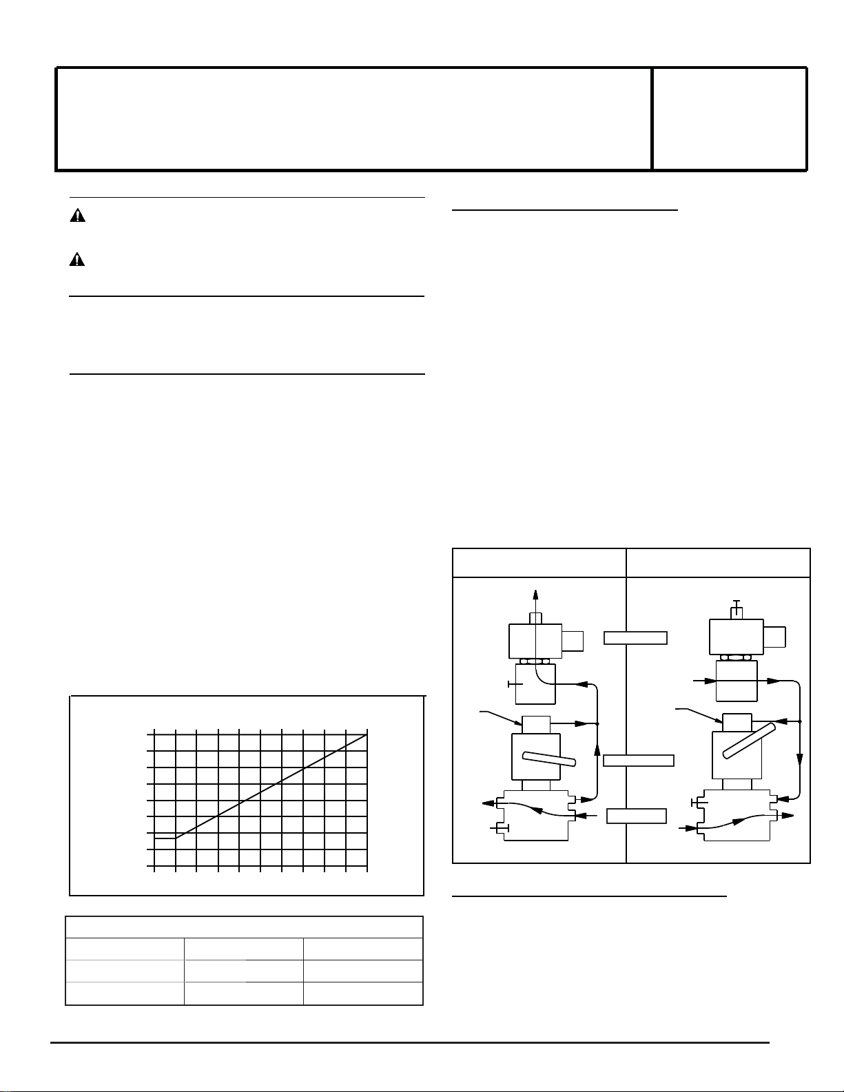
OPERATION
Auxiliary Piloting allows a zero minimum main line pressure
with the application of proper auxiliary air pressure. Refer
to Table 1, Operating Pressure Differential, and the graph
Auxiliary Pilot Pressure vs Main Line Pressure. Use this graph
to determine the minimum auxiliary air pressure required for a
given main line pressure.
Auxiliary Line Pressure vs Main Line Pressure
(Minimum Auxiliary Air 25 psi)
120
105
90
75
60
45
30
15
Auxiliary Line Pressure PSI
0
0 15 30 45 60 75 90 105 120 135 150
Table 1. Operating Pressure Differential
Valve Minimum Maximum
Main valve 0 150 psig
Pilot valve 25 125 psig
Main Line Pressure PSI
Unlatched - Solenoid De-energized: With valve unlatched and
the solenoid de-energized, main valve fl ow will be from cylinder
to exhaust. The pressure port is closed, whether or not auxiliary
pressure is present.
Latched - Solenoid Energized with Auxiliary Pressure
Applied: With solenoid energized and auxiliary pilot pressure
present, the valve may be manually operated (shifted) by raising
the handle until it latches the operator in the (up) latched position.
In the latched position, main valve fl ow will be from pressure to
cylinder. Exhaust will be closed. When solenoid is de-energized,
valve will return (trip) to the (down) unlatched position. Valve
can not be latched, until solenoid is energized, auxiliary pressure
applied, and handle is raised to the (up) latched position.
NOTE: Upon solenoid de-energization or loss of auxiliary pilot
valve pressure, valve will return (trip) to the unlatched position.
Valve can not be latched until auxiliary pilot pressure is restored,
solenoid is energized and lever handle is raised. The valve is now
latched.
Flow Diagrams for No-Voltage Release
UNLATCHED
DE-ENERGIZED
PILOT
EXH
‘3’
PILOT VALVE
PILOT
PRESSURE
PILOT
PISTON
CYLINDER
EXH
PRESS
For Electrically Tripped (TSO) Operation
Apply proper auxiliary pressure to port 3 of the pilot valve. Port 2
is now the auxiliary exhaust port - DO NOT BLOCK OFF.
Latched - Solenoid De-energized: With solenoid de-energized,
raise the handle until it latches in the (up) latched position. Main
valve fl ow is now from the pressure to the cylinder port. The
exhaust port of the main valve is closed.
‘2’ ‘1’
MANUAL RESET
AUX
MAIN VALVE
CYL
CATALOG
EV8308G360
EV8308G361
EV8310G361
Low Power
LATCHED
ENERGIZED
PILOT
PRESSURE
PILOT
PISTON
CYLINDER
EXH
PRESS
PILOT
EXH
‘3’
‘2’ ‘1’
AUX
CYL
ASCO Valves
©
ASCO Valve, Inc. 160 Park Avenue, Florham Park, New Jersey 07932 www.ascovalve.com Page 1 of 4
®
E269586 - 04/2017 All Rights Reserved. I&M V_9602_R2
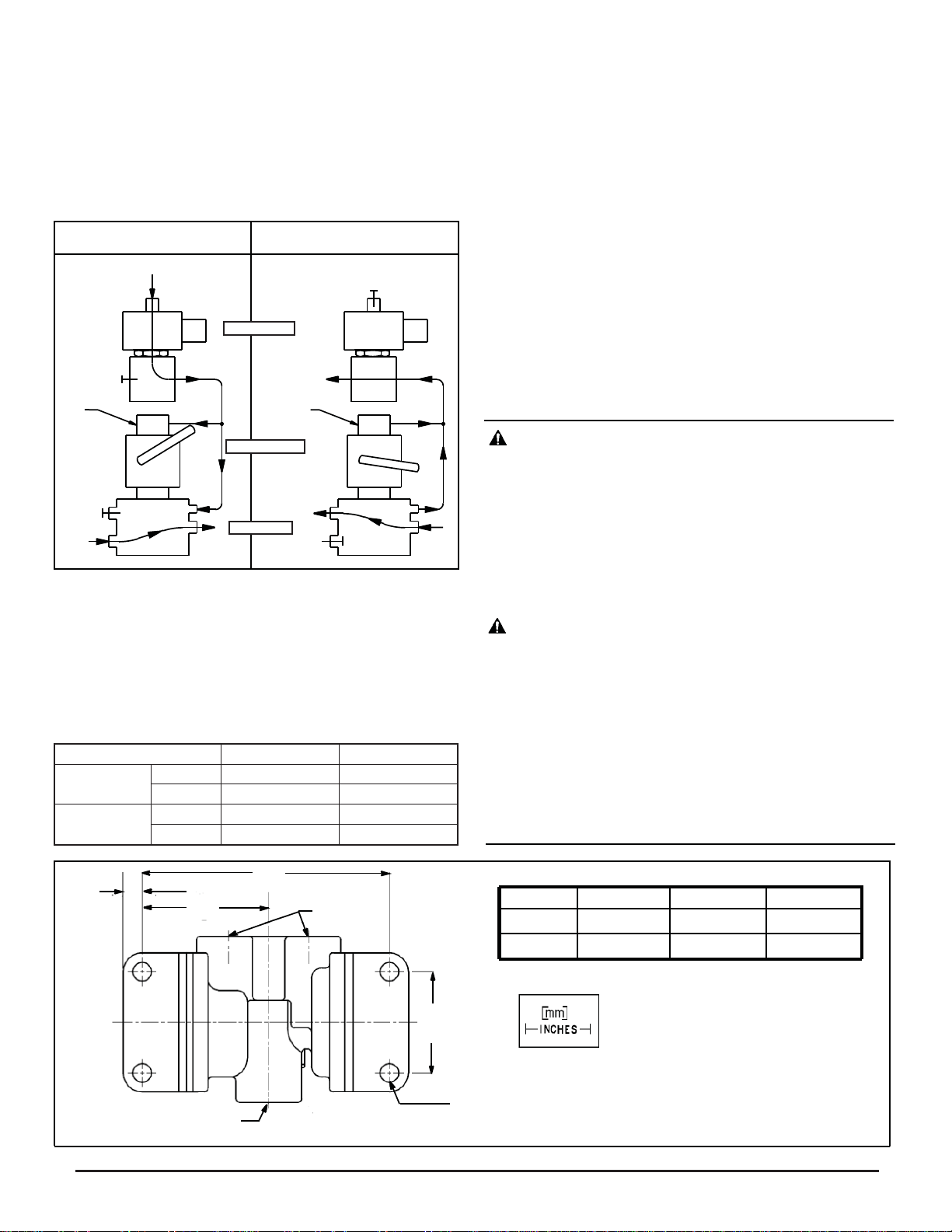
Unlatched - Solenoid Energized: With solenoid energized, the
handle will now return to the (down) unlatched position. The
pressure port of the main valve will close and fl ow in the main
valve will be from cylinder to exhaust.
NOTE: When piped in the electrically tripped (TSO) mode,
loss of auxiliary pressure will cause the operator to return to the
unlatched position - Main valve pressure will close and exhaust
will open.
Flow Diagrams for Electrically Tripped
DE-ENERGIZED
PILOT
PRESSURE
PILOT
EXH
PILOT
PISTON
CYLINDER
EXH
PRESS
LATCHED
‘3’ ‘3’
PILOT VALVE
‘2’ ‘1’
MANUAL RESET
AUX
MAIN VALVE
CYL
UNLATCHED
ENERGIZED
PILOT
PRESSURE
PILOT
EXH
PILOT
PISTON
CYLINDER
EXH
PRESS
‘2’ ‘1’
AUX
CYL
INSTALLATION
Check nameplate for correct catalog number, pressure, voltage,
frequency, and service. Never apply incompatible fl uids or exceed
pressure rating of the valve. Installation and valve maintenance
to be performed by qualifi ed personnel only.
Temperature Limitations
Please refer to chart below, or as limited by solenoid approvals.
See solenoid installation and maintenance instructions.
Temperatures Pilot Valve Main valve
Fluid
Ambient
Min. -4°F (-20°C) -4°F (-20°C)
Max. 140°F (60°C) 140°F (60°C)
Min. -4°F (-20°C) -4°F (-20°C)
Max. 140°F (60°C) 140°F (60°C)
Positioning
Valve may be mounted in any position. For optimum performance
mount with operator vertical and upright.
Mounting
For valve body mounting refer to Figure 1.
Piping
There are three exhaust fl ow modes: pilot valve, auxiliary pilot
and main valve exhaust. For pilot valve and auxiliary pilot exhaust
use a muffl er to vent to atmosphere or connect to main exhaust
system if the air or inert gas cannot be exhausted directly to the
atmosphere.
Connect piping or tubing to valve according to markings on valve
body. Refer to fl ow diagrams in OPERATION section and Figure
2 Valve Port Connections. Apply pipe compound sparingly to
male pipe threads only. If applied to valve threads, the compound
may enter the valve and cause operational diffi culty. Avoid
pipe strain by properly supporting and aligning piping. When
tightening the pipe, do not use valve or solenoid as a lever. Locate
wrenches applied to valve body or piping as close as possible to
connection point.
CAUTION: These solenoid valves are intended for
use on clean dry air, inert gas or natural gas, fi ltered to 40
micrometres or better. The dew point of the media should
be at least 10°C (18°F) below the minimum temperature
to which any portion of the clean air/inert gas system
could be exposed to prevent freezing. If lubricated air is
used, the lubricants must be compatible with FKM and/
or Nitrile elastomers. Diester oils may cause operational
problems. Instrument air in compliance with ANSI/ISA
Standard 7.0.01-1996 exceeds the above requirements
and is, therefore, an acceptable media for these valves.
ATTENTION : Ces électrovannes doivent être
utilisées avec de l’air sec, du gaz inerte ou gaz naturel
propre, fi ltré jusqu’à 40 micromètres ou plus. Le point
de rosée du fl uide doit être d’au moins 10ºC inférieur
à la température minimale à laquelle toute partie du
système d’air/gaz inerte propre pourrait être exposée,
afi n d’éviter le gel. En cas d’utilisation d’air lubrifi é,
les lubrifi ants doivent être compatibles avec le FKM
et/ou élastomères nitrile. Les huiles diester peuvent
engendrer des problèmes de fonctionnement. L’air
d’instrumentation conforme à la norme ANSI/ISA 7.0.011996 dépasse les exigences ci-dessus et constitue, par
conséquent, un média acceptable pour ces vannes.
.31 [8]
”D”
PRESS EXH
ANPT
”F”
CYL
ANPT
ANPT
1/4”
1/2”
”E”
Ø.28 [7]
4 MOUNTING HOLES
Figure 1. Mounting dimensions (partial view)
D
2.09 [53]
2.18 [55]
E
1.25 [32]
1.66 [42]
F
4.05 [103]
4.26 [108]
Page 2 of 4 I&M No. V_9602_R2
©ASCO Valve, Inc. 160 Park Avenue, Florham Park, New Jersey 07932 www.ascovalve.com
 Loading...