

ASCO Installationsanleitung: Cylinders and Actuators Mountings and sensors 449 453 IM 515137 001 Manuals & Guides
INSTALLATION AND MAINTENANCE INSTRUCTIONS
INSTRUCTIONS D’INSTALLATION ET DE MAINTENANCE
INBETRIEBNAHME - UND WARTUNGSANLEITUNG
INSTRUCCIONES DE PUESTA EN MARCHA Y MANTENIMIENTO
INSTRUZIONI DI MESSA IN SERVIZIO E MANUTENZIONE
ALGEMENE INSTALLATIE- EN ONDERHOUDSINSTRUCTIES
INSTALLASJONS- OG VEDLIKEHOLDSINSTRUKSER
INSTALLATIONS- OCH UNDERHÅLLSINSTRUKTIONER
ASENNUS - JA HUOLTO-OHJEET
INSTALLATIONS - OG VEDLIGEHOLDSANVISNINGER
INSTRUÇÕES DE INSTALAÇÃO E MANUTENÇÃO
ΟΔΗΓΙΕΣ ΤΟΠΟΘΕΤΗΣΗΣ ΚΑΙ ΣΥΝΤΗΡΗΣΗΣ
POKYNY PRO INSTALACI A ÚDRŽBU
INSTRUKCJA MONTAŻU I KONSERWACJI
TELEPÍTÉSI ÉS KARBANTARTÁSI ÚTMUTATÓ
Инструкция по установке и обслуживанию
설치 및유지 관리 지침
EN
FR
DE
ES
IT
NL
NO
SE
FI
DK
PT
GR
CZ
PL
HU
RU
KR
MT4
Series 449
MOUNTING
MT4
Series
449
453
Series 453
449 - 453
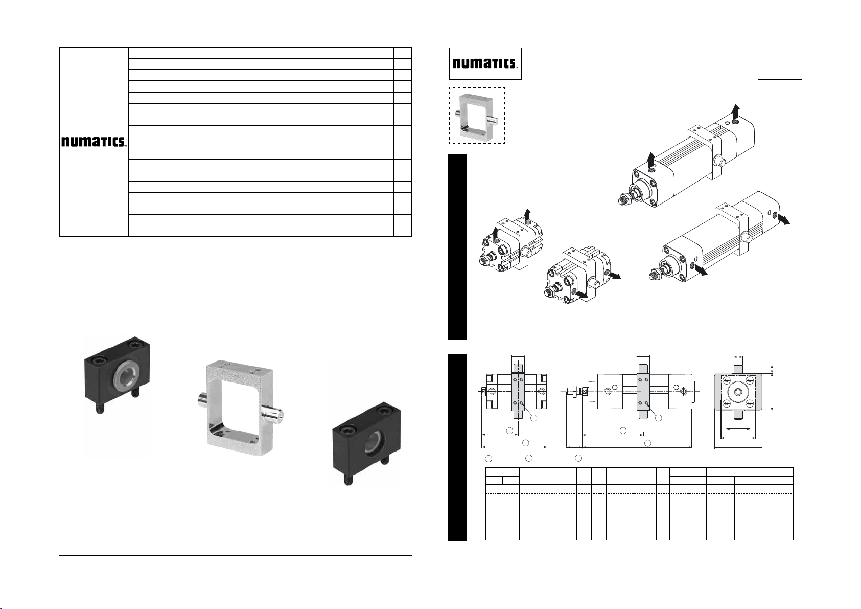
MT4 - MS4 CENTRE TRUNNION
+
q
ATEX
2
Fig. I
Fig. IIa
515137-001 / A
Availability, design and specifi cations are subject to change without notice. All rights reserved.
Series 453
MS4
MS4
XV + 2
Series 453
TK
ZJ + 1
e9
ØTD
33
XV min. XV max. (+ stroke) min. stroke
70
79
86
89
102
TG
==
E
==
UWA
==
27
27
28
107 5
30
119 5
35
132 5
h14
TL
h14
TM
77 5
86 5
95 5
515137-001515137-001
Series 449
TK
XV + 2
ZB + 1
2
Stroke
1
Ø (mm)
449 453 449 453 449 453 449
32
40
50
63
80
100
2 x Stroke
A E TD TG TK TL TM UWA ZB ZJ
22 46,5 12 32,5 18 12 53 64,5 55 120 31
24 52 16 38 20 16 63 74,5 55 135 32
32 64 16 46,5 20 16 75 91 56 143 33
32 74 20 56,6 25 20 90 94 59,5 158 35
40 92 20 72 25 20 110 130 66,5 174 40
40 109 25 89 30 25 132 145 87,5 189 45 109 42
A
3
8 locking screws.

Fig. IIb
T
XV
Ø (mm)
MOUNTING
Series 453
XV
STATIC ROD-LOCKING DEVICE DYNAMIC ROD-LOCKING DEVICE
XV min. XV max. (+ stroke) XV min. XV max. (+ stroke)
130 137 - -
32
149 156 174 181
40
176 185 198 207
50
179 197 209 227
63
212 229 242 259
80
100
219
242
259
282
Series
449
MOUNTING
453
4
1
XV
Fig. IV
1 et 4 2 et 3
2
3
8
5
6
7
4
1
2
3
Ø
items N.m
(mm)
32 - 40
50 - 63 - 80 f 1,5 13,22
100
e
1 et 4 2 et 3
f
g
Series
449
453
Inch.pounds
e 2 17,70
g
1 8,85
e
f
g
F
Fig. IIIa - IIIb
1 et 4 2 et 3
fi g .
IIIa
5 et 8 6 et 7
1
H
180°
1 et 4 2 et 3
5 et 8 6 et 7
4 5
fi g .
180°
IIIb
Fig. Va - Vb
fi g .
Va
Ø
(mm)
32
40
50
63
80
100
Ø T
(mm)
M5
M5
M6
M6
M8
M8
ØTp
H
7
Ø
Ø Tp
(mm)
4,6 11,5
4,6 13
5,5 16,5
5,5 13
7,5 21,7
7,5 20
(mm)
H
e
f
5 et 8 6 et 7
g
e
f
g
fi g .
1
7
Vb
e
f
g
e
f
g
515137-001515137-001
MOUNTING
Series
449
453
MT4 CENTRE TRUNNION
Fig. VI
UL
= =
TH
= =
Ø (mm)
449 453
Series 453Series 449
UL
= =
TH
= =
ØCRØ
d4 FK FN HB H3 L5 L6 NH TH TM UL
12 11 15 30 6,6 6,8 71 86 18 32 50 46
32
16 15 18 36 9 9 87 105 21 36 63 55
40
16 15 18 36 9 9 99 117 21 36 75 55
50
20 18 20 40 11 11 116 136 23 40 90 65
63
20 18 20 40 11 11 136 156 23 40 110 65
80
25 20 25 50 13,5 13 164 189 28,5 50 132 75
100
Ø (mm)
449 453
32 P493A3112100A00
(2 x)
AT4
40 / 50 P493A4112100A00
63 / 80 P493A6112100A00
100 P493A1112100A00
Fitting the MT4 centre trunnion on 449-453 cylinders allows a choice of position. The centre trunnion slides along
the barrel to allow on-site adjustment. For that reason, it
is delivered unlocked.
ASSEMBLING THE CENTRE TRUNNION
1. Check that trunnion is correctly oriented (fi g.
Use appropriate tooling to ensure the perpendicularity with the cylinder.
Two orientations: axes of the centre trunnion perpendicular to the air ports (MT4 option), paralell to air
Ød4
=
H9
==
Ø CR
==
h14
L5
L6
TM
==
=
H3
FN
==
FK
Ø HB
UL
TH
==
NH
C
ports (MS4 option)
2. Adjust the centre trunnion to the desired position
along the barrel. (dimension XV) (fi g.IIa - IIb)
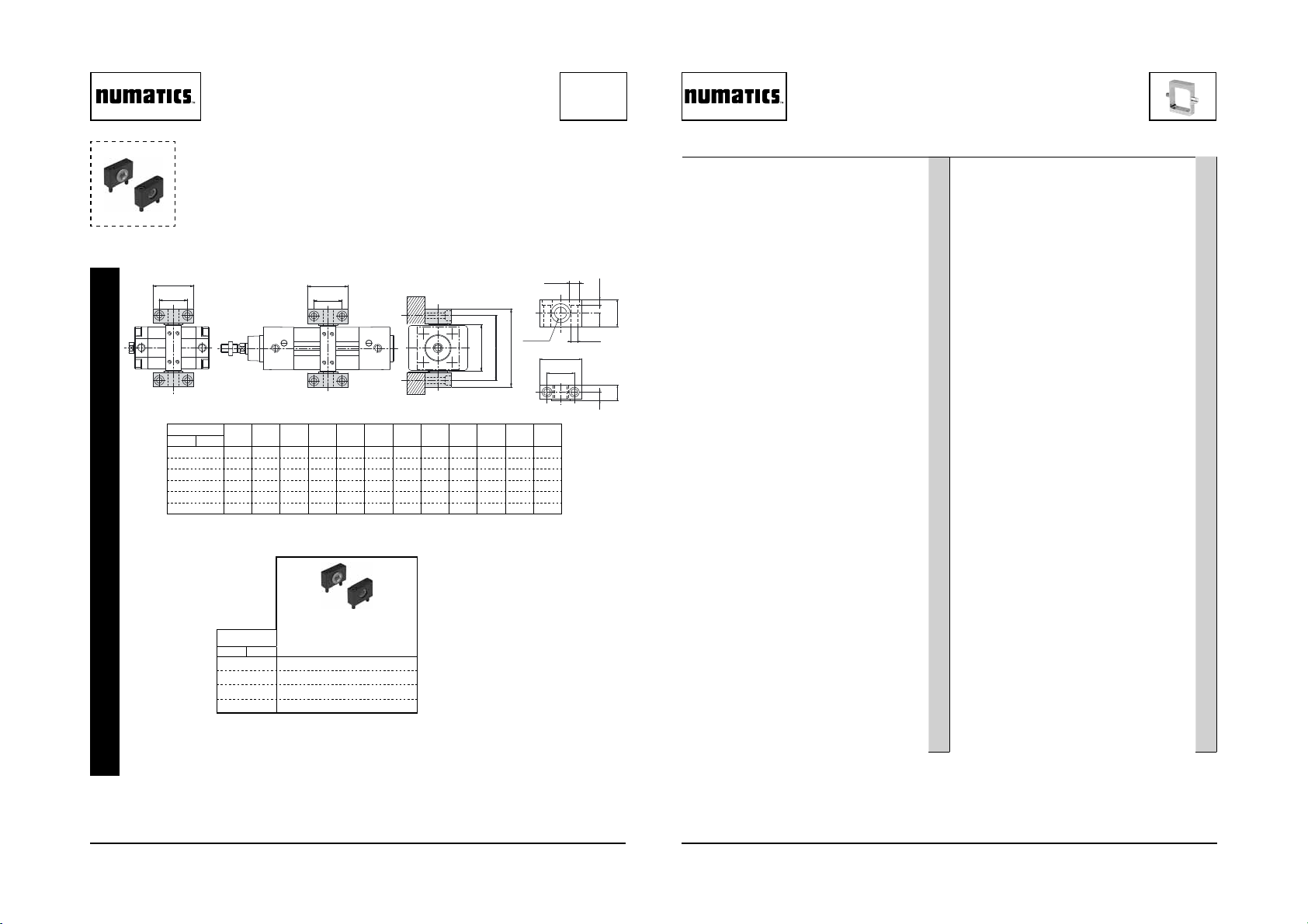
3. Manually tighten the 4 set screws on one side, in
such a way that the opposite side is in contact with
the tube. (fi g.IIIa)
4. Unscrew 1/2 turn these 4 set screws and manually
tighten the set screws on the opposite side. (fi g.IIIb)
5. With the centre trunnion positioned and oriented on
the tube, proceed tightening the set screws. (see
tightening sequence fi g.IV)
- Slightly tighten crosswise the set screws on one side,
without reaching the torque.
- Tighten the other side in the same way.
- Apply torque in the 8 set screws (see table).
1. Unscrew and remove one set screw (ØT) on each
2. Pierce the 2 empty holes (ØTp). See table and
3. Re-insert the two set screws and tighten in the full
-
- Grease the axes of the spindle before mounting.
- Fix the supports with the centre trunnion mounted to
MECHANICAL LOCKING (Fig.V)
side of the centre trunnion. (fi g.
Va, 1 - 7)
(fi g Va) for drilling depht H.
depth of the hole. (fi g.Vb)
MOUNTING SUPPORTS FOR CENTRE TRUNNION
The supports enable mounting according to
ensure proper alignment.
I).
(fi g.VI).
La fi xation par tourillon MT4 des cylindres 449 et 453
permet un montage oscillant. Ce tourillon coulisse le long
du tube pour permettre le réglage en position sur site.
A cet effet, il est livré non bloqué sur le tube.
1. S’assurer que les axes du tourillon sont correcte-
2. Placer le tourillon à l’emplacement souhaité sur le
3. Serrer manuellement les 4 vis d’un même coté, de
4. Dévisser d’un 1/2 tour ces 4 vis et serrer manuelle-
5. Avec le tourillon positionné et orienté sur le tube,
- Serrer modérement et en croix sur l’un des coté, sans
- Serrer le coté opposé de manière identique.
- Appliquer le couple sur les 8 vis pointeaux (voir
EN
1. Dévisser et retirer l’une des vis pointeaux (ØT) sur
2. Percer le tube à travers les 2 trous libres du tourillon
3. Réintroduire les 2 vis pointeaux pour venir tarauder
- Les supports de tourillon permettant l’adaptati
-
- Fixer les supports avec le tourillon monté pour assu-
ASSEMBLAGE DU TOURILLON
ment orientés (fi g.
Utiliser un outil approprié pour assurer la perpendicularité avec le vérin.
Deux orientations : axe du tourillon
-
perpendiculaire aux orifi ces d’alimentation (option MT4)
-parallèle aux orifi ces d’alimentation (option MS4).
I).
tube (dimension XV) (fi g.IIa - IIb)
telle sorte que le coté opposé soit en contact avec
le tube. (fi g.IIIa)
ment les 4 vis sur le coté opposé. (fi g.IIIb)
procédé au serrage des vis pointeaux. [voir séquence de serrage (fi g.IV)]
appliquer le couple.
tableau).
BLOCAGE MECANIQUE (Fig.V)
chaque coté du tourillon. (fi g.
(ØTp). Voir le tableau (fi g.Va) pour un perçage à la
profondeur H.
le tube de façon à assurer un blocage parfait entre le
tube et la fi xation, serrer au couple prescrit (fi g.Vb).
Va, 1 - 7).
ADAPTATION SUPPORTS TOURILLON
vant la (
fi g . VI).
Graisser les axes du tourillon lors du montage.
rer le bon alignement.
FR
on sui-
6 7
515137-001515137-001
 Loading...