

INSTALLATION AND MAINTENANCE INSTRUCTIONS
INSTRUCTIONS D’INSTALLATION ET DE MAINTENANCE
INBETRIEBNAHME - UND WARTUNGSANLEITUNG
INSTRUCCIONES DE PUESTA EN MARCHA Y MANTENIMIENTO
INSTRUZIONI DI MESSA IN SERVIZIO E MANUTENZIONE
ALGEMENE INSTALLATIE- EN ONDERHOUDSINSTRUCTIES
INSTALLASJONS- OG VEDLIKEHOLDSINSTRUKSER
INSTALLATIONS- OCH UNDERHÅLLSINSTRUKTIONER
ASENNUS - JA HUOLTO-OHJEET
INSTALLATIONS - OG VEDLIGEHOLDSANVISNINGER
INSTRUÇÕES DE INSTALAÇÃO E MANUTENÇÃO
ΟΔΗΓΙΕΣ ΤΟΠΟΘΕΤΗΣΗΣ ΚΑΙ ΣΥΝΤΗΡΗΣΗΣ
POKYNY PRO INSTALACI A ÚDRŽBU
INSTRUKCJA MONTAŻU I KONSERWACJI
TELEPÍTÉSI ÉS KARBANTARTÁSI ÚTMUTATÓ
ИНСТРУКЦИЯ ПО УСТАНОВКЕ И ОБСЛУЖИВАНИЮ
ОРНАТУ ЖƏНЕ ҚЫЗМЕТ КӨРСЕТУ НҰСҚАУЛАР
651 - 652 - 653
EN
FR
DE
ES
IT
NL
NO
SE
FI
DK
PT
GR
CZ
PL
HU
RU
KZ
651- 652 - 653
R FR FRL VERSIONS
652 SERIES
q
IN CONFORMITY WITH ATEX DIRECTIVE
Products requiring approval are those that have their own potential ignition risk. These product categories include
moving parts. They are labelled with the CE marking and the explosion protection hexagon; operating instructions
and the EC declaration of conformity are provided.
These conditioning units of compressed air are envisaged for use in explosive atmospheres in the form of gas,
steam, mists and dust.
The classification into zones 1-21 of these units is defined by the following markings: II2GD IIC T85°C (T6) X
or II2GD IIC T100°C (T5) X.
Compliance with essential health and safety requirements is guaranteed by conformity to the European Standard
EN 13463-1.
This specific ATEX documentation is supplied as an addition to the general user instructions where detailed product information is provided.
______________________________________________________________________________________________
!
SPECIAL CONDITIONS FOR SAFE “X” USAGE :
Ambient temperature range and temperature classification
PRODUCTS:
- REGULATOR
ambient
P1 max.
- MANIFOLD REGULATOR
temperature range
TT°C
(bar)
(°C)
- AIR PILOT OPERATED REGULATOR
4..37
-20 to +50
STANDARD
16 T6 85
Low Temperature
-40 to +50
High Temperature
-20 to +80 16 T5 100
FPM/FKM
-20 to +50 16 T6 85
Low/High Temperature
-40 to +80 16 T5 100
High Temperature + FPM/FKM
-20 to +80 16 T5 100
ambient
P1 max.
- FILTER/REGULATOR
bowl
temperature
TT°C
(bar)
EN
range (°C)
plastic*
-20 to +50 16 T6 85
STANDARD
metal
plastic*
Low Temperature
-40 to +50 16 T6 85
metal
plastic*
High Temperature
-20 to +80 16 T5 100
metal
plastic*
FPM/FKM
-20 to +50 16 T6 85
metal
plastic*
Low/High Temperature
-40 to +80 16 T5 100
metal
plastic*
High Temperature + FPM/FKM
-20 to +80 16 T5 100
metal
* : Only with manual/semi auto drain.
ambient
P1 max.
- COALESCING FILTER/REGULATOR
bowl
temperature
TT°C
(bar)
range (°C)
plastic*
+1,7 to +50 16 T6 85
STANDARD
metal
plastic*
High Temperature
+1,7 to +80 16 T5 100
metal
plastic*
FPM/FKM
+1,7 to +50 16 T6 85
metal
plastic*
High Temperature + FPM/FKM
+1,7 to +80 16 T5 100
metal
* : Only with manual/semi auto drain.
516023-001
3
651 + 652 + 653 Series
&
q
F- FR - FRL VERSIONS
1/8-1/4 (651)
q
ATEX
1/4-3/8-1/2 (652)
2 3
1/2-3/4-1 (653)
516682-001 / B
Availability, design and specifi cations are subject to change without notice. All rights reserved.
1
3
metal
2
&
fi g. A
&
polycarbonate
516682-001516682-001

R FR FRL VERSIONS
IN CONFORMITY WITH ATEX DIRECTIVE
651/652/653 SERIES
Products requiring approval are those that have their own potential ignition risk. These product categories include
moving parts. They are labelled with the CE marking and the explosion protection hexagon; operating instructions
and the EC declaration of conformity are provided.
These conditioning units of compressed air are envisaged for use in explosive atmospheres in the form of gas,
steam, mists and dust.
The classifi cation into zones 1-21 of these units is defi ned by the following markings: II2GD IIC T85°C (T6) X
or II2GD IIC T100°C (T5) X.
Compliance with essential health and safety requirements is guaranteed by conformity to the European Standard
EN 13463-1.
This specifi c ATEX documentation is supplied as an addition to the general user instructions where detailed product information is provided.
______________________________________________________________________________________________
!
SPECIAL CONDITIONS FOR SAFE “X” USAGE :
PRODUCTS:
- REGULATOR
- MANIFOLD REGULATOR
- AIR PILOT OPERATED REGULATOR
STANDARD
Low Temperature
High Temperature
FPM/FKM
Low/High Temperature
High Temperature + FPM/FKM
- FILTER/REGULATOR
STANDARD
Low Temperature
High Temperature
FPM/FKM
Low/High Temperature
High Temperature + FPM/FKM
Ambient temperature range and temperature classifi cation
ambient
temperature range
plastic
metal
plastic
metal
plastic
metal
plastic
metal
plastic
metal
plastic
metal
(°C)
-20 to +50
-40 to +50
-20 to +80 T5 100
-20 to +50 T6 85
-40 to +80 T5 100
-20 to +80 T5 100
bowl
ambient
temperature
range (°C)
-20 to +50
-40 to +50
-20 to +80 16 20 T5 100
-20 to +50
-40 to +80 16 20 T5 100
-20 to +80 16 20 T5 100
651/652 653
16 20
651/652 653
16 12
16 20
16 12
16 20
16 12
16 20
P1 max.
(bar)
P1 max.
(bar)
q
T T°C
T6 85
T T°C
T6 85
T6 85
T6 85
EN
R FR FRL VERSIONS
IN CONFORMITY WITH ATEX DIRECTIVE
651/652/653 SERIES
Risk from electrostatic charges:
For the IIC Group, prevent electrostatic charging of external insulating surfaces by using the appropriate installation and cleaning measures. To clean external insulating surfaces use a damp cloth.
Connect the conditioning units to the earth.
When combined with other conditioning units, ensure that all metallic and conductive parts are always intercon-
nected and linked to the earth to avoid signifi cant electrostatic charges being created.
The earth is connected to the unit or to the combination of conditioning units by the downstream and upstream
use of metal pipes connected to the earth. If the pipes are non-conductive, earth connection should be performed
by the assembly and/or fi xing devices adapted to the ATEX products.
_____________________________________________________________________________________________
Installation, commissioning and servicing and maintenance
These operations may only be carried out by authorised personnel and in accordance with the usage instructions.
Only carry out maintenance in zones where there is no explosive atmosphere.
If during maintenance it is established that wearing and spare parts need exchanging, contact an ASCO NUMAT-
ICS reseller.
Any modifi cation of the product with parts not supplied by the manufacturer will invalidate the certifi cation.
Assembly of conditioning units
The assembly comprises components which are individually certifi ed. Therefore assembly comprised in this way
does not generate any additional risk. Each component has a marking which is bespoke to that component and
the assembly category corresponds to the most unfavourable category of one of the components of the
assembly.
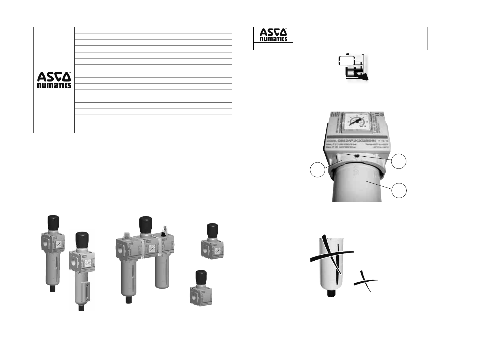
Product fi tted with a metal tank: FR and FRL (see fi g. A)
When replacing a fi lter element saturated by the FR (fi lter/regulator), proceed as described below:
• Loosen the screw (1)
• Remove the tank (2) from the body (3)
• Remove the fi lter element and replace with a new one
• Replace the tank (2)
• Tighten the screw (1) in the body (3) up to the contact of the tank and screw one quarter to a half turn extra
in order to ensure ground continuity.
For adding oil to the lubricator tank, proceed in the same manner as above.
q
EN
- COALESCING FILTER/REGULATOR
STANDARD
High Temperature
FPM/FKM
High Temperature + FPM/FKM
ambient
temperature
range (°C)
+1,7 to +50
+1,7 to +80 16 20 T5 100
+1,7 to +50
+1,7 to +80 16 20 T5 100
4 5
plastic
metal
plastic
metal
plastic
metal
plastic
metal
bowl
P1 max.
(bar)
651/652 653
16 12
16 20
16 12
16 20
T T°C
T6 85
T6 85
516682-001516682-001

VERSIONS R FR FRL
EN CONFORMITE AVEC LA DIRECTIVE ATEX
SERIES 651/652/653
Les produits nécessitant une approbation sont ceux qui ont leur propre risque d’infl ammation potentielle. Ces catégories de produits comprennent les pièces mobiles. Ils sont marqués avec le marquage CE et l’hexagone de protection
contre les explosions; les instructions de mise en service et la déclaration CE de conformité sont fournies.
Ces unités de conditionnement de l’air comprimé sont prévues pour être utilisées en atmosphères explosibles
sous forme de gaz, vapeurs, brouillards et poussières.
Le classement en zones 1-21 de ces unités est défi ni par le marquage suivant : II2GD IIC T85°C (T6) X ou
II2GD IIC T100°C (T5) X.
Le respect des exigences essentielles en ce qui concerne la sécurité et la santé est assuré par la conformité à
la norme européenne EN 13463-1.
Cette documentation spécifi que ATEX vient en complément de la notice d’instructions d’utilisation générales où des informations détaillées sur le produit sont données.
_____________________________________________________________________________________________
!
CONDITIONS SPECIALES POUR UNE UTILISATION SURE « X » :
PRODUITS :
- REGULATEUR
- REGULATEUR JUXTAPOSABLE
- REGULATEUR A COMMANDE PNEUMATIQUE
STANDARD
Basse température
Haute température
FPM/FKM
Basse/haute température
Haute température + FPM/FKM
- FILTRE/REGULATEUR
STANDARD
Basse température
Haute température
FPM/FKM
Basse/haute température
High Temperature + FPM/FKM
Plage de température ambiante et classifi cation en température
plage de
température ambiante
(°C)
-20 à +50
-40 à +50
-20 à +80 T5 100
-20 à +50 T6 85
-40 à +80 T5 100
-20 à +80 T5 100
cuve
plastique
métal
plastique
métal
plastique
métal
plastique
métal
plastique
métal
plastique
métal
plage de
température
ambiante (°C)
-20 à +50
-40 à +50
-20 à +80 16 20 T5 100
-20 à +50
-40 à +80 16 20 T5 100
-20 à +80 16 20 T5 100
P1 maxi
(bar)
651/652 653
16 20
P1 maxi
(bar)
651/652 653
16 12
16 20
16 12
16 20
16 12
16 20
q
T T°C
T6 85
T T°C
T6 85
T6 85
T6 85
FR
VERSIONS R FR FRL
EN CONFORMITE AVEC LA DIRECTIVE ATEX
SERIES 651/652/653
Risque dû aux charges électrostatiques :
Pour le groupe IIC, empêcher le chargement électrostatique des surfaces isolantes externes à l’aide de mesures
d’installation et de nettoyage appropriées. Pour le nettoyage des surfaces isolantes externes utiliser un chiffon
humide.
Raccorder à la terre les unités de conditionnement.
Lors d’une combinaison avec d’autres unités de conditionnement, s’assurer que toutes les parties métalliques ou
conductrices soient toujours interconnectées et reliées à la terre pour éviter la formation de charges électrostatiques importantes.
La liaison à la terre de l’unité ou de la combinaison d’unités de conditionnement se fait par l’utilisation en aval
et en amont de canalisations métalliques raccordées à la terre. Dans le cas de canalisations non conductrices,
la mise à la terre doit être faite avec les dispositifs d’assemblage et/ou de fi xation adaptés aux produits ATEX.
______________________________________________________________________________________________
Montage, mise en service, maintenance et entretien
Ces opérations peuvent être effectuées uniquement par du personnel agréé et conformément aux instructions
d’utilisation.
Réaliser l’entretien uniquement dans des zones où l’atmosphère explosive n’est pas présente.
Dans le cadre d’une maintenance et d’un besoin de remplacement de pièces d’usure et de rechange prendre
contact avec un revendeur ASCO NUMATICS.
Toute modifi cation du produit avec des pièces non fournies par le fabriquant invalidera la certifi cation.
Assemblage d’unités de conditionnement
L’assemblage est constitué de composants individuellement certifi és. L’assemblage ainsi constitué ne génère pas
de risque supplémentaire. Chaque composant a un marquage qui lui est propre et la catégorie de l’assemblage
correspond à la catégorie la plus défavorable de l’un des composant de l’assemblage.
Produit équipé de cuve métallique : FR et FRL (Voir fi g. A)
Lors d’un remplacement d’élément fi ltrant saturé du FR (fi ltre/régulateur), procéder comme décrit ci-dessous :
• Dévisser la vis (1)
• Enlever la cuve (2) du corps (3)
• Retirer l’élément fi ltrant et le remplacer par un neuf
• Remettre la cuve (2) en place
• Revisser la vis (1) dans le corps (3) jusqu’au contact de la cuve et effectuer ¼ à ½ tour supplémentaire pour
assurer la continuité de masse.
Pour ajouter de l’huile dans la cuve du Lubrifi cateur, procéder de la même façon que ci-dessus.
q
FR
- FILTRE/REGULATEUR COALESCEUR
STANDARD
Haute température
FPM/FKM
High Temperature + FPM/FKM
plage de
cuve
plastique
métal
plastique
métal
plastique
métal
plastique
métal
température
ambiante (°C)
+1,7 à +50
+1,7 à +80 16 20 T5 100
+1,7 à +50
+1,7 à +80 16 20 T5 100
6 7
P1 maxi
(bar)
651/652 653
16 12
16 20
16 12
16 20
T T°C
T6 85
T6 85
516682-001516682-001

R FR FRL VERSIONEN
IN ÜBEREINSTIMMUNG MIT DER ATEX-RICHTLINIE
651/652/653-SERIE
Für Produkte mit eigenem potenziellen Entzündungsrisiko ist eine Genehmigung erforderlich. Diese Produktkategorien umfassen bewegliche Teile. Sie verfügen über eine CE-Kennzeichnung und das Explosionsschutz-Achteck.
Eine Betriebsanleitung und die EG-Konformitätserklärung werden mitgeliefert.
Diese Druckluft-Konditioniereinheiten sind für die Verwendung in explosionsfähigen Atmosphären in Form von Gas,
Dampf, Nebel und Staub gedacht.
Die Klassifi zierung dieser Einheiten in Zonen 1 bis 21 wird durch die folgenden Kennzeichnungen festgelegt: II2GD
IIC T85°C (T6) X oder II2GD IIC T100°C (T5) X.
Die Erfüllung grundlegender Gesundheits- und Sicherheitsanforderungen wird durch Einhaltung der europäischen
Norm EN 13463-1 garantiert.
Diese spezifi sche ATEX-Kommunikation wird als Ergänzung der allgemeinen Bedienungsanleitung geliefert,
in der genauere Informationen zum Produkt angegeben sind.
______________________________________________________________________________________________
!
SPEZIELLE BEDINGUNGEN FÜR DIE SICHERE „X“-VERWENDUNG :
PRODUKT:
- REGLER
- VENTILINSELREGLER
- PILOTLUFTBETÄTIGTER REGLER
STANDARD
Niedrige Temperatur
Hohe Temperatur
FPM/FKM
Niedrige/Hohe Temperatur
Hohe Temperatur + FPM/FKM
- FILTER/REGLER
STANDARD
Niedrige Temperatur
Hohe Temperatur
FPM/FKM
Niedrige/Hohe Temperatur
Hohe Temperatur + FPM/FKM
Umgebungstemperaturbereich und Temperaturklassifi zierung
Umgebungstemperaturbereich
Schale
Kunststoff
Metall
Kunststoff
Metall
Kunststoff
Metall
Kunststoff
Metall
Kunststoff
Metall
Kunststoff
Metall
(°C)
-20 bis +50
-40 bis +50
-20 bis +80 T5 100
-20 bis +50 T6 85
-40 bis +80 T5 100
-20 bis +80 T5 100
Umgebungstempe-
raturbereich (°C)
-20 bis +50
-40 bis +50
-20 bis +80 16 20 T5 100
-20 bis +50
-40 bis +80 16 20 T5 100
-20 bis +80 16 20 T5 100
P1 max.
651/652 653
16 20
P1 max.
651/652 653
16 12
16 20
16 12
16 20
16 12
16 20
(bar)
(bar)
q
T T°C
T6 85
T T°C
T6 85
T6 85
T6 85
DE
R FR FRL VERSIONEN
IN ÜBEREINSTIMMUNG MIT DER ATEX-RICHTLINIE
651/652/653-SERIE
Risiko elektrostatischer Aufl adungen:
Für die IIC-Gruppe elektrostatische Aufl adung externer Isolierfl ächen durch Verwendung geeigneter Installationsund Reinigungsmaßnahmen vermeiden. Zum Reinigen der externen Isolierfl ächen ein feuchtes Tuch verwenden.
Konditioniereinheiten an die Erde anschließen.
Bei Kombination mit anderen Konditioniereinheiten sicherstellen, dass metallische und leitende Teile immer verbunden
und an die Erde angeschlossen sind, um die Erzeugung erheblicher elektrostatischer Aufl adungen zu vermeiden.
Die Erde ist mit dem Gerät oder der Kombination von Konditioniereinheiten durch vor- oder nachgeschaltete
Verwendung von Metallrohren verbunden, die mit der Erde verbunden sind. Falls die Rohre nicht leitend sind,
sollte der Erdanschluss durch die Baugruppe und/oder Befestigungselemente durchgeführt werden, die an die
ATEX-Produkte angepasst sind.
_____________________________________________________________________________________________
Installation, Inbetriebnahme sowie Service- und Wartungsarbeiten
Diese Vorgänge dürfen nur von autorisiertem Personal und in Übereinstimmung mit den Gebrauchsanweisungen
durchgeführt werden.
Wartung nur in Bereichen ausführen, in denen keine explosionsfähige Atmosphäre vorhanden ist.
Falls während der Wartung festgestellt wird, dass Verschleiß- und Ersatzteile ausgetauscht werden müssen, einen
ASCO NUMATICS-Händler kontaktieren.
Alle Modifi zierungen des Produkts durch Teile, die nicht vom Hersteller geliefert wurden, machen die Zertifi zierung
ungültig.
Baugruppe der Konditioniereinheiten
Die Baugruppe umfasst Komponenten, die einzeln zertifi ziert sind. Daher führt eine solche Baugruppe zu keinen
zusätzlichen Risiken. Jede Komponente hat eine Kennzeichnung, die speziell für diese Komponente gilt, und die
Baugruppenkategorie entspricht der ungünstigsten Kategorie einer der Komponenten der Montage.
Produkt mit einem Metalltank ausgestattet: FR und FRL (siehe Abb. A)
Beim Austausch eines vom FR (Filter/Regler) gesättigten Filterelements wie unten beschrieben vorgehen:
• Schraube (1) lösen
• Tank (2) vom Gehäuse (3) entfernen
• Filterelement entfernen und durch ein neues ersetzen
• Tank (2) wieder anbringen
• Schraube (1) im Gehäuse (3) anziehen, bis sie den Tank berührt, und eine viertel bis halbe Umdrehung zusätzlich drehen, um gute Erdung sicherzustellen.
Zum Hinzufügen von Öl zum Schmiertank genauso wie oben beschrieben vorgehen.
q
DE
- KOALESZENZ-FILTER/REGLER
STANDARD
Hohe Temperatur
FPM/FKM
Hohe Temperatur + FPM/FKM
Umgebungstempe-
Schale
Kunststoff
Metall
Kunststoff
Metall
Kunststoff
Metall
Kunststoff
Metall
raturbereich (°C)
+1,7 bis +50
+1,7 bis +80 16 20 T5 100
+1,7 bis +50
+1,7 bis +80 16 20 T5 100
8 9
P1 max.
(bar)
651/652 653
16 12
16 20
16 12
16 20
T T°C
T6 85
T6 85
516682-001516682-001
VERSIONES R FR FRL
EN CONFORMIDAD CON LA DIRECTIVA ATEX
SERIE 651/652/653
Los productos que requieren aprobación son aquellos que presentan su propio riesgo de encendido potencial.
Estas categorías de productos incluyen piezas móviles. Dichos productos están etiquetados con la marca CE y el
hexágono de protección contra explosión; se proporcionan instrucciones de uso y la declaración de conformidad
de la CE.
Estas unidades de acondicionamiento de aire comprimido se han diseñado para utilizarse en atmósferas explosivas en forma de gas, vapor, nieblas y polvo.
La clasifi cación en las zonas 1-21 de estas unidades se defi ne con las marcas siguientes: II2GD IIC T85°C (T6)
X o II2GD IIC T100°C (T5) X.
La conformidad con los requisitos esenciales de salud y seguridad se garantiza con la conformidad de la Norma
europea EN 13463-1.
Esta documentación específi ca de ATEX se suministra como complemento de las instrucciones de uso
general donde se proporciona información detallada del producto.
______________________________________________________________________________________________
!
CONDICIONES ESPECIALES PARA EL USO SEGURO DE “X”:
PRODUCTOS:
- REGULADOR
- REGULADOR DEL COLECTOR
- REGULADOR DE ACCIONAMIENTO NEUMÁTICO PILOTO
ESTÁNDAR
Temperatura baja
Temperatura alta
FPM/FKM
Temperatura alta/baja
Temperatura alta + FPM/FKM
- FILTRO/REGULADOR
ESTÁNDAR
Temperatura baja
Temperatura alta
FPM/FKM
Temperatura alta/baja
Temperatura alta + FPM/FKM
Intervalo de temperaturas ambiente y clasifi cación de temperatura
intervalo de
temperatura ambiente
(°C)
-20 a +50
-40 a +50
-20 a +80 T5 100
-20 a +50 T6 85
-40 a +80 T5 100
-20 a +80 T5 100
recipiente
plástico
metal
plástico
metal
plástico
metal
plástico
metal
plástico
metal
plástico
metal
intervalo de
temperatura
ambiente (°C)
-20 a +50
-40 a +50
-20 a +80 16 20 T5 100
-20 a +50
-40 a +80 16 20 T5 100
-20 a +80 16 20 T5 100
P1 máx.
(bar)
651/652 653
16 20
P1 máx.
(bar)
651/652 653
16 12
16 20
16 12
16 20
16 12
16 20
q
T T°C
T6 85
T T°C
T6 85
T6 85
T6 85
ES
VERSIONES R FR FRL
EN CONFORMIDAD CON LA DIRECTIVA ATEX
SERIE 651/652/653
Riesgo de cargas electroestáticas:
Para el Grupo IIC, evite la carga electroestática de superfi cies de aislamiento externas utilizando las medidas de
limpieza e instalación adecuadas. Para limpiar las superfi cies de aislamiento externas, utilice un paño húmedo.
Conecte las unidades de acondicionamiento a tierra.
Cuando se combine con otras unidades de acondicionamiento, asegúrese de que todas las piezas metálicas y
conductivas estén siempre interconectadas y conectadas a tierra para evitar la creación de cargas electroestáticas
signifi cativas.
La tierra se conecta a la unidad o a la combinación de unidades de acondicionamiento mediante el uso aguas
abajo y aguas arriba de tubos de metal conectados a la tierra. Si los tubos son no conductivos, la conexión a
tierra debe efectuarse con el conjunto o los dispositivos de fi jación adaptados a los productos ATEX.
_____________________________________________________________________________________________
Instalación, puesta en marcha y servicio y mantenimiento
Estas operaciones solo pueden ser realizadas por personal autorizado y de acuerdo con las instrucciones de uso.
Realice el mantenimiento únicamente en zonas donde no exista atmósfera explosiva.
Si durante el mantenimiento se establece la necesidad de cambiar piezas de desgaste y repuesto, póngase en
contacto con el distribuidor de ASCO NUMATICS.
Cualquier modifi cación del producto con piezas no suministradas por el fabricante invalidará la certifi cación.
Montaje de unidades de acondicionamiento
El conjunto consta de componentes que están certifi cados individualmente. Por tanto, el ensamblaje compuesto
de esta manera no genera ningún riesgo adicional. Cada componente tiene una marca que es específi ca de
dicho componente y la categoría de ensamblaje corresponde a la categoría más desfavorable de uno de
los componentes del ensamblaje.
Producto equipado con un tanque metálico: FR y FRL (consulte la fi g. A)
Al reemplazar un elemento de fi ltro saturado por el FR (fi ltro/regulador), proceda como se indica a continuación:
• Afl oje el tornillo (1)
• Extraiga el tanque (2) del cuerpo (3)
• Extraiga el elemento de fi ltro y reemplácelo por uno nuevo
• Vuelva a colocar el tanque (2)
• Apriete el tornillo (1) en el cuerpo (3) hasta el contacto del tanque y atornille de un cuarto a media vuelta
adicional para garantizar continuidad a tierra.
Para agregar aceite al tanque del lubricador, proceda de la misma manera que anteriormente.
q
ES
- FILTRO/REGULADOR COALESCENTE
ESTÁNDAR
Temperatura alta
FPM/FKM
Temperatura alta + FPM/FKM
recipiente
plástico
metal
plástico
metal
plástico
metal
plástico
metal
intervalo de
temperatura
ambiente (°C)
+1,7 a +50
+1,7 a +80 16 20 T5 100
+1,7 a +50
+1,7 a +80 16 20 T5 100
10 11
P1 máx.
(bar)
651/652 653
16 12
16 20
16 12
16 20
T T°C
T6 85
T6 85
516682-001516682-001

VERSIONI R FR FRL
IN CONFORMITÀ ALLA DIRETTIVA ATEX
SERIE 651/652/653
I prodotti che richiedono un’approvazione sono quelli che presentano un loro proprio rischio potenziale di accensione. Queste categorie di prodotti includono le parti in movimento. Esse presentano il contrassegno CE e
l’esagono di protezione dalle esplosioni; sono fornite le istruzioni d’impiego e la dichiarazione di conformità EC.
Queste unità di condizionamento d’aria compressa sono previste per l’impiego in atmosfere esplosive, sotto forma
di gas, vapore, nebbioline e polveri.
La classifi ca nelle zone 1-21 di queste unità è defi nita dai seguenti contrassegni: II2GD IIC T85°C (T6) X oppure
II2GD IIC T100°C (T5) X.
L’osservanza delle regolamentazioni essenziali per la salute e la sicurezza è garantita dalla conformità alle Normativa europea EN 13463-1.
Questa documentazione specifi ca ATEX è fornita come aggiunta alle istruzioni generali per l’utente, quando
sono fornite informazioni dettagliate del prodotto.
______________________________________________________________________________________________
!
CONDIZIONI SPECIALI PER L’IMPIEGO IN SICUREZZA “X”:
PRODOTTI:
- REGOLATORE
- REGOLATORE DEL COLLETTORE
- REGOLATORE OPERATO DAL PILOTA D’ARIA
STANDARD
Bassa temperatura
Alta temperatura
FPM/FKM
Bassa/Alta temperatura
Alta temperatura + FPM/FKM
- FILTRO/REGOLATORE
STANDARD
Bassa temperatura
Alta temperatura
FPM/FKM
Bassa/Alta temperatura
Alta temperatura + FPM/FKM
Intervallo di temperatura ambientale e classifi ca delle temperature
intervallo
temperatura ambientale
(°C)
da -20 a +50
da -40 a +50
da -20 a +80 T5 100
da -20 a +50 T6 85
da -40 a +80 T5 100
da -20 a +80 T5 100
vasca
plastica
metallo
plastica
metallo
plastica
metallo
plastica
metallo
plastica
metallo
plastica
metallo
intervallo
temperatura
ambientale (°C)
da -20 a +50
da 40 a +50
da -20 a +80 16 20 T5 100
da -20 a +50
da -40 a +80 16 20 T5 100
da -20 a +80 16 20 T5 100
P1 max.
(bar)
651/652 653
16 20
P1 max.
(bar)
651/652 653
16 12
16 20
16 12
16 20
16 12
16 20
q
T T °C
T6 85
T T °C
T6 85
T6 85
T6 85
R FR FRL VERSIONS
IN CONFORMITY WITH ATEX DIRECTIVE
651/652/653 SERIES
Rischio da scariche elettrostatiche:
Per il Gruppo IIC, prevenire il caricamento elettrostatico delle superfi ci esterne isolanti servendosi delle misure
appropriate d’installazione e di pulizia. Per la pulizia delle superfi ci isolanti esterne, utilizzare un panno umido.
Connettere le unità di condizionamento alla messa a terra.
Una volta combinate alle altre unità di condizionamento, assicurarsi che tutte le parti metalliche e conduttrici si-
ano sempre interconnesse e collegate alla messa a terra, al fi ne di evitare la creazione di cariche elettrostatiche
signifi cative.
La terra è connessa all’unità o alla combinazione di unità di condizionamento per mezzo di tubazioni metalliche
connesse a terra, in discesa e in salita. Nel caso che le tubazioni siano non conduttrici, la connessione di messa
a terra dev’essere attuata dall’assemblaggio e/o dal fi ssaggio di dispositivi adatti ai prodotti ATEX.
_____________________________________________________________________________________________
Installazione, commissioning, servizio e manutenzione
Queste operazioni possono essere eseguite soltanto da personale autorizzato e in conformità alle istruzioni d’impiego.
Eseguire gli interventi di manutenzione soltanto in zone in cui sia assente un’atmosfera esplosiva.
Se, durante la manutenzione, si scopre che parti d’usura e di ricambio devono essere sostituite, mettersi in con-
tatto con un rivenditore ASCO NUMATICS.
Qualsiasi modifi ca del prodotto, mediante parti non fornite dal costruttore, renderà invalida la certifi cazione.
Assemblaggio delle unità di condizionamento
L’assemblaggio comprende componenti che sono certifi cati individualmente. Di conseguenza, l’assemblaggio effettuato in questo modo non crea alcun rischio addizionale. Ogni componente presenta un contrassegno su misura
per il componente in questione, e la categoria d’assemblaggio corrisponde alla categoria più sfavorevole di
un singolo componente dell’assemblaggio.
Prodotto dotato di un serbatoio metallico: FR e FRL (vedere la Fig. A)
Quando si sostituisce un elemento fi ltrante, saturato dal FR (fi ltror/regolatore), procedere come indicato qui sotto:
• Allentare la vite (1)
• Rimuovere il serbatoio (2) dal corpo (3)
• Rimuovere l’elemento fi ltrante e sostituirlo con uno nuovo
• Sostituire il serbatoio (2)
• Serrare la vite (1) nel corpo (3) fi no ad entrare in contatto con il serbatoio e ruotare la vite ancora per un quarto
o mezzo giro supplementare, per assicurare una continuità di messa a terra.
IT
Per aggiungere olio al serbatoio del lubrifi cante, procedere nello stesso modo di cui sopra.
q
IT
- IN CORSO DI FUSIONE FILTRO/REGOLATORE
STANDARD
Alta temperatura
FPM/FKM
Alta temperatura + FPM/FKM
vasca
plastica
metallo
plastica
metallo
plastica
metallo
plastica
metallo
intervallo
temperatura
ambientale (°C)
da +1,7 a +50
da +1,7 a +80 16 20 T5 100
da +1,7 a +50
da +1,7 a +80 16 20 T5 100
12 13
P1 max.
(bar)
651/652 653
16 12
16 20
16 12
16 20
T T °C
T6 85
T6 85
516682-001516682-001
 Loading...