


Sentronic
Installation Manual
PLUS
Electronic Pressure Regulator
Sentronic
PLUS
INSTALLATION
MANUAL
AVENTICS™
Sentronic
PLUS
Electronic Pressure Regulator
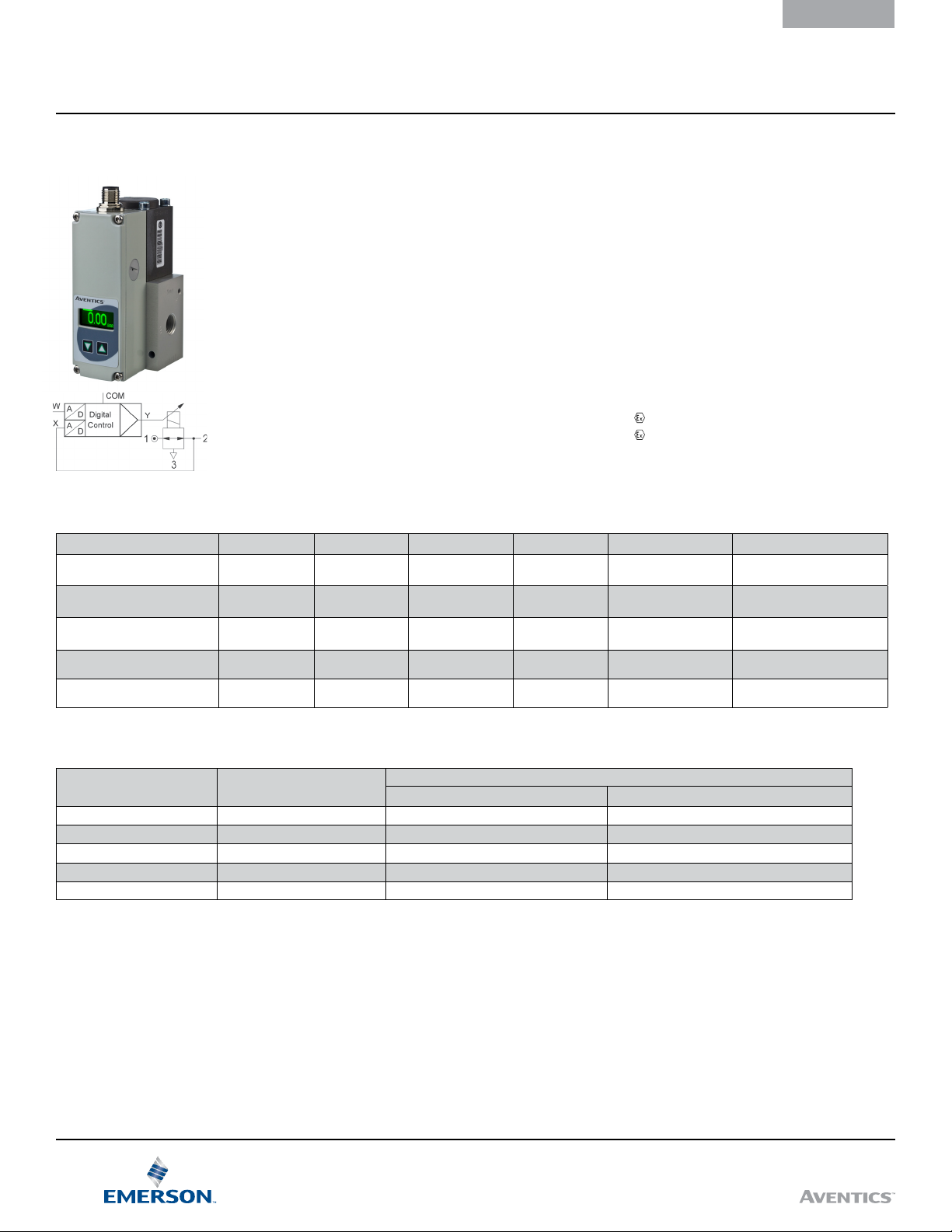
General
Sentronic
control. The Data Acquisition Software (DaS) that
comes with Sentronic
valve's control parameters to a specic application.
Command signal, feedback signal and control
parameters can be viewed in real time and adjusted
as required for an application. Sentronic
congured for dual loop control of process variables such
as ow, force, speed, RPM, and temperature.
PLUS
is a 3-way proportional valve with digital
PLUS
can be used to adjust the
Construction
Direct-operated poppet valve
Body: See table below.
Internal parts: Stainless steel and brass
Seals: FPM (uoroelastomer) and NBR (nitrile)
Specifications
Fluids: Air or neutral gas, ltered at 50 µm,
condensate-free, lubricated or unlubricated
PLUS
can be
Specifications
Fluids: Air or neutral gas, ltered at 50 µm,
condensate-free, lubricated or unlubricated
Ports: 1/8 - 1/4 - 1/2 - 1 (NPT or GTap)
Max. operating pressure: See table below.
Control range: See table below.
Temperature / uid: 32ºF - 140ºF (0ºC - 60°C)
Temperature / ambient: 32ºF - 140ºF (0ºC - 60°C)
Command signal - analog: 0 - 10 V (impedance 100 KΩ)
0 - 20 mA/4 - 20 mA
(impedance 250 Ω)
Hysteresis: 1% of span
Linearity / pressure measurement: ± 0.5% of span
Repeatability: ± 0.5% of span
EXPLOSION SAFETY
Safety code: II 3D Ex tc IIIC T135°C Dc X
II 3G EX ec IIC T4 Gc X, 0 ≤ Ta ≤ = 50°C
Electrical Characteristics
Nominal Diameter DN (mm) Voltage * Max. Power (W)Max. Current (mA) Insulation Class Degree of Protection Electrical Connection
5-pin M12 connector
or 7-pin DIN connector
5-pin M12 connector
or 7-pin DIN connector
5-pin M12 connector
or 7-pin DIN connector
5-pin M12 connector
or 7-pin DIN connector
5-pin M12 connector
or 7-pin DIN connector
* Max. ripple: 10 %
1 24 VDC = ±10% 12 500 F IP 65
3 24 VDC = ±10% 12 500 F IP 65
6 24 VDC = ±10% 24
12 24 VDC = ±10% 34 1400 F IP 65
20 24 VDC = ±10% 44 1800 F IP 65
7)
1000
1
F IP 65
Specifications
Ø
Ports
1/8 NPT or GTap 1 0.032 (0.028) 30
1/8 NPT or GTap 3 0.21 (0.18) 210
1/4 NPT or GTap 6 0.70 (0.60) 700
1/2 NPT or GTap 12 1.39 (1.20) 1400
1 NPT or GTap 20 5.57 (4.80) 5600
Notes: 1) For DN6, brass version GorH/1.8A, 44W
2
Ø
Orifice DN (mm)
Flow Factor (K
C
v
Visit our website at Emerson.com/AVENTICS
Nm3/h) at 6 Bar (l/min - ANR)
v
Flow

AVENTICS™
How to Order
6 1 4 3 5 7 E 9 0 1 1 PB
Control Panel
D = M12 with display - non-explosionproof
E = M12 without display - explosionproof (ATEX)
F = DIN connector, 7-pin with display - non-explosion proof
G = DIN connector, 7-pin without display - non-explosion proof
Version (ports), body
0 = DN6 (G 1/4), ALU 7 = DN3 (G 1/8), Brass
1 = DN12 (G 1/2), ALU2) 9 = DN3 (NPT 1/8), Brass
2 = DN20 (G 1), ALU2) C = DN6 (G 1/4), Stainless Steel
4 = DN6 (NPT 1/4), ALU G = DN6 (NPT 1/4), Brass
5 = DN12 (NPT 1/2), ALU2) H = DN6 (G 1/4), Brass
6 = DN20 (NPT 1), ALU2) J = DN1 (G 1/8), Brass
K = DN1 (NPT 1/8), Brass
Command Signal
0 = 0 ... 10 Volt
1 = 0 ... 20 mA
2 = 4 ... 20 mA
Feedback
1 = Feedback output 0 ... 10 Volt
2 = Feedback output 0 ... 20 mA
3 = Feedback output 4 ... 20 mA
4 = Feedback input 0 ... 10 Volt
5 = Feedback input 0 ... 20 mA
6 = Feedback input 4 ... 20 mA
1)
1)
3)
3)
Sentronic
PLUS
INSTALLATION
MANUAL
Options
A00 = Dual Loop Control
018 = Oxygen Clean
Pressure Range
Relative pressure (psi)
40 = 0 - 0.1 bar (1.5)
50 = 0 - 0.5 bar (7.3)
60 = 0 - 1 bar (14.5)
02 = 0 - 2 bar (29)
03 = 0 - 3 bar (44)
05 = 0 - 5 bar (73)
06 = 0 - 6 bar (87)
PB = 0 - 6.9 bar (100)
10 = 0 - 10 bar (145)
12 = 0 - 12 bar (174)
16 = 0 - 16 bar
4)
4)
4)
20 = 0 - 20 bar5) (290)
3H = 0 - 30 bar6) (435)
5H = 0 - 50 bar
Digital Output
1 = Pressure switch output
PNP ± 5 %
5)
(232)
6)
(725)
Max. inlet
pressure bar (psi)
2 (29)
2 (29)
2 (29)
3 (44)
8 (116)
8 (116)
12 (174)
12 (174)
12 (174)
14 (203)
18 (261)
22 (316)
40 (580)
60 (870)
Vacuum (relative)
V1 = -1 bar
Shut-off valve, connects to
vacuum on loss of power
V2 = 0...-1 bar
Bypass valve
V3 = 0...-1 bar
Shut-off valve, connects
to atmosphere on loss of
power
Notes: 1) 7-pin DIN connector allows crossover from 833-354 or 601 Series analog Sentronic version; ships with eld installable connector. 2) Up to max. 12 bar. 3) Only for pressure ranges from 30 to 50
4)
bar.
Feedback input is needed for dual loop units. 5) Only for DN3 & DN6 6) Only for DN6 body type G or H. Other versions available on request. 7)For DN6, brass version GorH/1.8A, 44W
Visit our website at Emerson.com/AVENTICS
3
 Loading...