

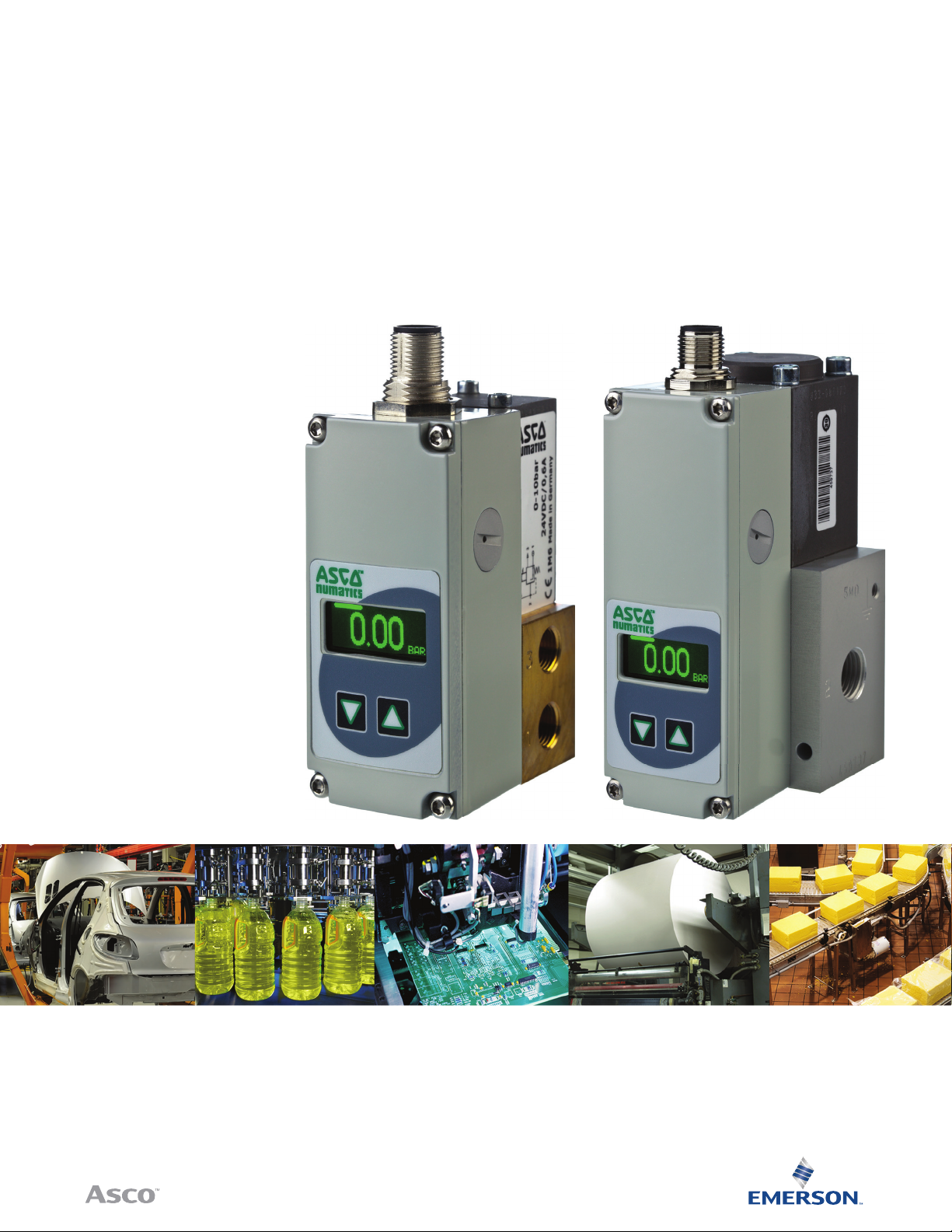
Sentronic
Electronic Pressure Regulator
Installation Manual
PLUS
IO-Link CLASS A
Sentronic
PLUS
INSTALLATION
MANUAL
ELECTRONIC
PRESSURE REGULATOR
ASCO NUMATICS™
Sentronic
Sentronic
•
Direct operated valve
•
Dynamic behavior (high speed)
•
IO - Link CLASS A Version
•
RoHS, REACH compliant
Air or neutral gas, ltered at 50 µm,
condensate-free, lubricated or
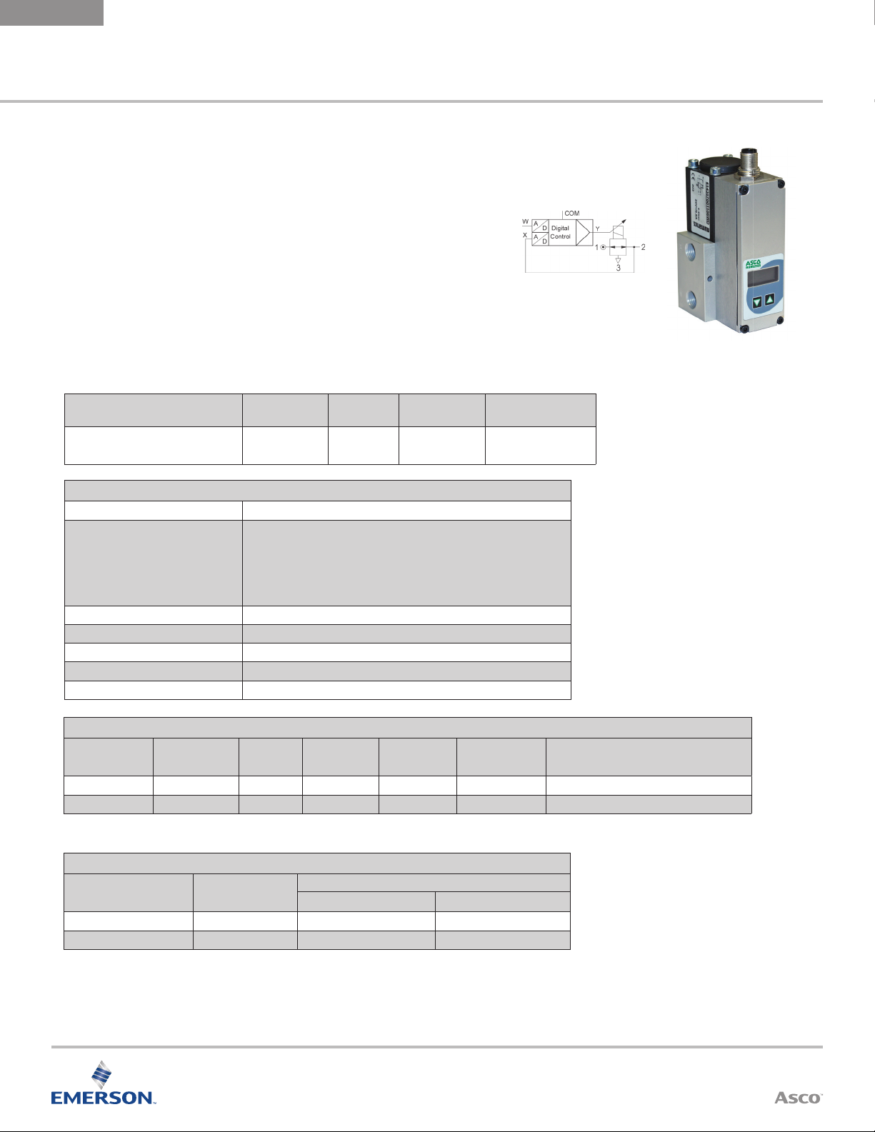
PLUS
Electronic Pressure Regulator
PLUS
is a 3-way proportional valve with digital control.
Fluids
unlubricated
Ambient
Temperature
0 °C to 60 °C
(32 ºF to 140 ºF)
Aluminum
General Valve Information
Fluid Temperature 0 ºC to 60 ºC (32 °F to 140 °F)
PSI Pressure Ranges:
PA & PB (50 & 100 psi ranges): in digital steps of 0.01 psi
PC (150 psi range): in digital steps of 0.1 psi
Command Signal- IO-Link
Ports 1/8, 1/4 (NPT or GTap)
Construction Direct-operated Poppet Valve
Hysteresis 0.5% of span
Linearity/ pressure measurement ± 0.5% of span
Repeatability ± 0.5% of span
Bar Pressure Ranges:
40, 50, 60, V1, V2 & V3 (100mbar, 500mbar, 1bar & all vacuum): in digital
steps of 0.00 01 bar
All others: in digital steps of 0.001 bar
Body
Internal
Parts
Stainless steel
and brass
Seals
NBR (nitrile) and
FPM ( uoroelastomer)
2
Electrical Characteristics
Nominal
Diameter DN
(mm)
3 24 VDC = ± 10% 12 500 F IP65 5-pin M12 connector or 7-pin DIN connector
6 24 VDC = ± 10% 24
* Max. ripple: 10%
1
For DN6, b rass version G o r H/1.8A, 44W
Volt age *
Max.
Power (W)
1
Max. Current
(mA)
1
1000
Insulation
Class
F IP65 5-pin M12 connector or 7-pin DIN connector
Degree of
Protection
Electrical Connection
Specifi cations
Ø
Ports
1/8 NPT or GTap 3 0.21 (0.18) 210
1/4 NPT or GTap 6 0.70 (0.60) 700
Ø
Orifi ce DN
(mm)
Cv Flow Fac tor (K
Visit our website at ASCO.com or contact us at (800) 972-2726
Flow
Nm3/h) at 6 Bar ( l/min - A NR)
v
ASCO NUMATICS™
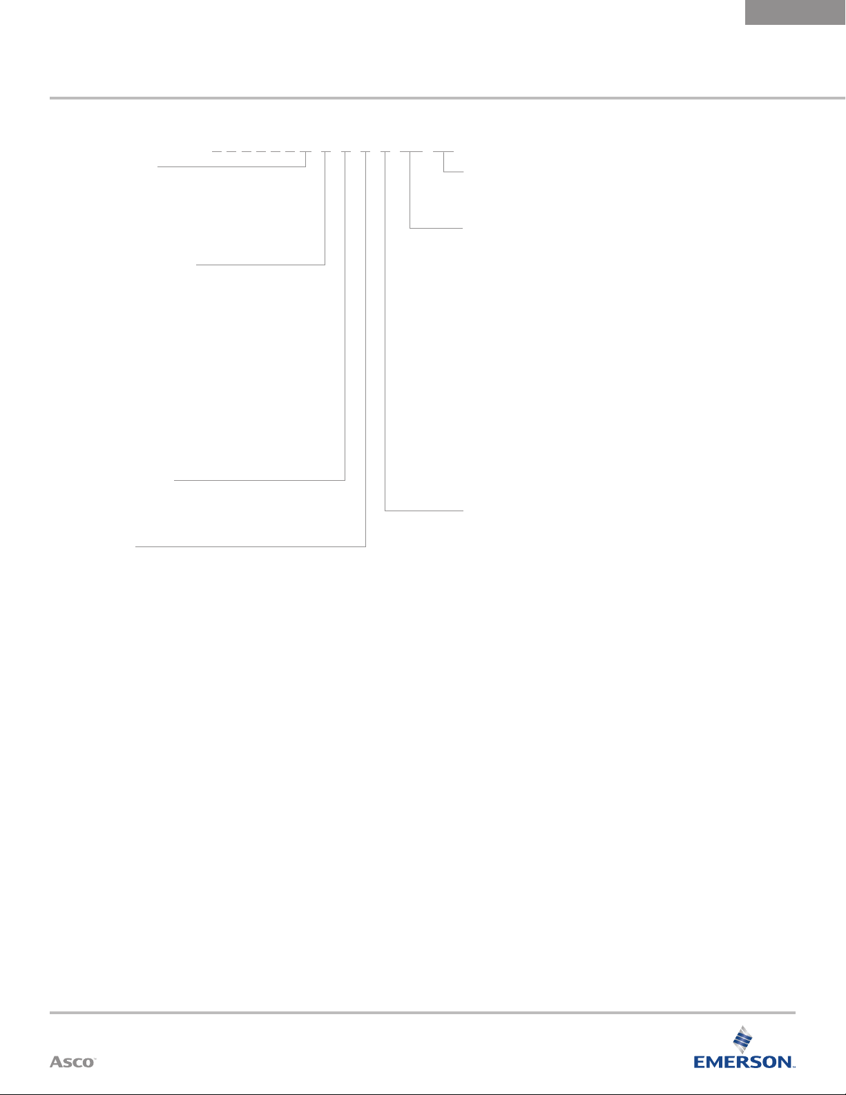
How to Order
6 1 4 3 5 7 E 9 0 1 1 PB
Control Panel
B = IO-LINK with display
C = IO-Link without display
ELECTRONIC
PRESSURE REGULATOR
Options
A00 = Dual loop control
018 = Oxygen clean
Sentronic
PLUS
INSTALLATION
MANUAL
Version
0 = DN6 (G 1/4), ALU
4 = DN6 (NPT 1/4), ALU
7 = DN3 (G 1/8), Brass
8 = DN6 (G 1/4), Brass
9 = DN3 (NPT 1/8), Brass
A = DN6 (NPT 1/4), Brass
C = DN6 (G 1/4), Stainless Steel
Command Signal
B = IO-LINK CLASS A
Feedback
B = IO-LINK CLASS A
(ports)
, Body
Pressure Range
Output Pressure
(psi)
40 = 0 – 0.1 bar (1.5)
50 = 0 – 0.5 bar (7.3)
60 = 0 – 1 bar (14.5)
02 = 0 – 2 bar (29)
03 = 0 – 3 bar (44)
PA = 0 – 3.4 bar (50)
05 = 0 – 5 bar (73)
06 = 0 – 6 bar (87)
PB = 0 – 6.9 bar (100)
10 = 0 – 10 bar (145)
PC = 0 – 10.3 bar (150)
12 = 0 – 12 bar (174)
Digital Output
1 = Standard
Max. Inlet
Pressure
(psi)
2 (29)
2 (29)
2 (29)
3 (44)
8 (116)
8 (116)
8 (116)
12 (174)
12 (174)
12 (174)
12 (174)
14 (203)
Vacuum
(relative)
V1 = 0 to -1 bar
Shut-off valve,
connects to
vacuum on loss
of power
V2 = 0 to -1 bar
Bypass valve
V3 = 0 to -1 bar
Shut-off valve,
connects to
atmosphere on
loss of power
Absolute Pressure
Ranges Available
on Request
Operating Modes
Shut-o:
If the setpoint falls below 0.5 %, the coil current is switched o and the valve is fully exhausted.
Overtemperature:
If the temperature of the internal control electronics exceeds 100°C, the operating mode is switched to AUTOSAFE.
Undervoltage / overvoltage:
If the supply voltage is less than 18 V or more than 30 V, the coil current is switched o and the valve is fully
exhausted.
Autosafe:
If the coil current exceeds a certain value, dependent on the mechanics, for more than 20 seconds, the output
current is limited to max. 70% to prevent the valve from overheating.
Visit our website at ASCO.com or contact us at (800) 972-2726
3
 Loading...