

Page 1
531
24
2
4
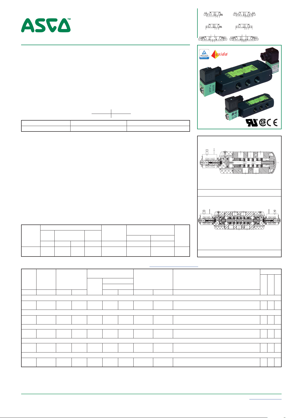
SPOOL VALVES
14
12
24
531
12
24
531
14
14
12
24
531
14
12
24
531
12
531
14
12
531
14
5/2-5/3
pilot operated or air operated, spool type
single/dual solenoid or air
aluminium body, 1/4 - 1/2
24
FEATURES
• All the exhaust ports of the spool valve are connectable, providing better environmental
protection. Particularly recommended for sensitive areas, such as clean rooms, and
applications in the pharmaceutical and food processing sectors
• The valves offer environmental protection against the ingress of liquids, dusts or
other foreign matter (environmentally-protected construction)
• The monostable spool valves in conformity with IEC 61508 Standard (2010 route 2H
version) have TÜV (551 series) and EXIDA (551-553 series) certified with integrity
levels: SIL 2 for HFT = 0 / SIL 3 for HFT = 1
• The solenoid valves satisfy all relevant EU directives
GENERAL
Differential pressure 2 - 10 bar [1 bar = 100 kPa]
Flow (Qv at 6 bar) l/min (ANR)
1/4 1/2
860 3800
fluids () temperature range (TS) seal materials ()
air, inert gas, filtered
-25°C to +60°C NBR (nitrile) + PUR (polyurethane)
MATERIALS IN CONTACT WITH FLUID
()
Ensure that the compatibility of the fluids in contact with the materials is verified
Body, end cover Aluminium, black anodized
End cover (spring return) Glass fibre filled PA
Spool valve internal parts Zamak, stainless steel, POM, aluminium
Seals NBR + PUR
Core tube Brass
Core and plugnut Stainless steel
Shading coil Copper
ELECTRICAL CHARACTERISTICS
Coil insulation class F
Connector Spade plug (cable Ø 6-8 mm or Ø 6-10 mm)
Connector specification
or ISO 4400 / EN 175301-803, form A (
EN 175301-803, 11 mm, industry standard form B (type 01)
type
02)
Electrical safety IEC 335
Electrical enclosure protection
Moulded IP65 (EN 60529)
Standard voltages DC (=) : 24V - 48V
(Other voltages and 60 Hz on request) AC (~) : 24V - 48V - 115V - 230V / 50 Hz
power ratings
prefix
option
inrush
~
holding
~
hot/cold
=
(VA) (VA) (W) (W) (C°)
SC 6 3,5 2,5 2,5 / 3 -25 to +60 400127-097 400904-542 01
SC 15 7 5 4 / 5 -25 to +60 400727-117 400727-185 02
(1)
Refer to the dimensional drawings on the following page
SPECIFICATIONS
pipe
size
orifice
size
G (mm) (m3/h) (l/min) ~ = ~ = ~/=
flow
coefficient
Kv
min.
operator
ambient
temperature
range (TS)
operating pressure
differential (bar)
max. (PS)
air (*)
replacement coil
~ =
230 V/50 Hz 24 V DC
Configurator - CAD Files
power coil
(W)
type
(1)
catalogue
number
5/2 - Solenoid air pilot operated - spring return (monostable)
1/4 6 0,75 12,5 2 10 10 2,5 3 SCG551A017 MS - -
1/2 13 3,15 52,5 2 10 10 5 5 SCG553A017 MS - -
5/2 - Solenoid air pilot operated and return (bistable)
1/4 6 0,75 12,5 2 10 10 2,5 3 SCG551A018 MS - -
1/2 13 3,15 52,5 2 10 10 5 5 SCG553A018 MS - -
5/3 - W1 - pressure held, solenoid air pilot and return
1/4 6 0,75 12,5 2 10 10 2,5 3 SCG551A067 MS - -
1/2 13 3,15 52,5 2 10 10 5 5 SCG553A067 MS - -
5/3 - W3 - pressure released, solenoid air pilot and return
1/4 6 0,75 12,5 2 10 10 2,5 3 SCG551A068 MS - -
1/2 13 3,15 52,5 2 10 10 5 5 SCG553A068 MS - -
5/2 - Solenoid air pilot operated spring return (monostable), certified IEC 61508 Functional Safety data
1/4 6 0,75 12,5 2 10 10 2,5 3 SCG551A017SL - - -
1/2 13 3,15 52,5 2 10 10 5 5 SCG553A017SL - - -
5/2 function
5
5/3 function
24
3
1
maintained
Series
551
553
options
man. operator
00093GB-2017/R01
Availability, design and specifications are subject to change without notice. All rights reserved.
All leaflets are available on: www.asco.com
Pneumatic Valves (5/2 - 5/3) - 5
Page 2
SOLENOID VALVES SERIES 551-553
210
13
13
75
52
M5
59
95
1
24
5
3
B
94,5
161,5
189
31,6 31,8
78,5 43
40,2
==
72,3
=
=
51
=
=
75 31,6
G1/4
5 x 1/2
1 34 25
1 34 25
5
12 10
1
72
125
146
3
45
=
=
27,5
=
=
32
=
=
5x 1/4
G1/8
21,8
==
50,5 32
4 2
A
41
==
AIR OPERATED AND OPTIONS
• Versions (Type 03): - pilot air operated, spring return, catalogue numbers: G551A117 / G551A117SL (1/4);
G553A117 / G553A117SL (1/2)
- pilot air operated and return, catalogue numbers: G551A118 (1/4); G553A118 (1/2)
• Suffix “GD“ (air operated only, ATEX 2GD c)
• Explosionproof enclosures for use in zones 1/21-2/22, categories 2-3 to ATEX Directive 2014/34/EU (www.asco.com)
• Supply rail (www.asco.com)
• Other pipe connections are available on request
• Connector with visual indication and peak voltage suppression or with cable length of 2 m (www.asco.com)
INSTALLATION
• The valves can be mounted in any position without affecting operation
• It is necessary to connect pipes or fittings to the exhaust ports to protect the internal parts of the spool valve and its pneumatic
operator if used outside or in harsh environments (dusts, liquids etc.)
• IEC 61508 Functional Safety (suffix SL). Check temperature range of valve body and solenoid for suitability. For probability of
failure, contact us
• Valves with suffix “SL” are supplied with specific exhaust protectors
• Threaded pipe connection is standard: G = G (ISO 228/1)
• Installation/maintenance instructions are included with each valve
ACCESSORIES
series
pipe
size
551 G 1/4 34600419
553 G 1/2 34600479
551-553 M5 34600484
(1)
Supplied with suffix “SL”
exhaust protector
(stainless steel)
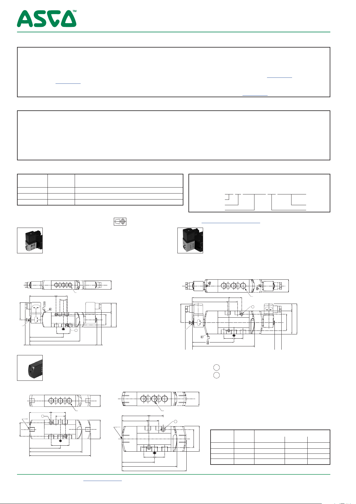
DIMENSIONS (mm), WEIGHT (kg)
TYPE 01
Prefix “SC” Solenoid
Epoxy moulded
IEC 335 / DIN 43650
82,5 32
180°
1
°
360
104,5
IP65
0
4 2
513
==
157
1 34 25
21,8
41
==
5 x 1/4
==
1
27,5
30
=
=
45
32
=
=
551A017 / A017MS / A017SL / A018 / A018MS
551A067 / A067MS / A068 / A068MS
ORDERING EXAMPLES:
SC G 551 A 017 MS 230V / 50 Hz
SC G 551 A 017 SL 24V / DC
(1)
(1)
(1)
pipe thread
basic number
SC G 553 A 018 115V / 50 Hz
G 551 A 117 SL
prefix
voltage
suffix
Configurator - CAD Files
TYPE 02
Prefix “SC” Solenoid
Epoxy moulded
IEC 335 / ISO 4400
553A017 / A017MS / A018 / A018MS / A067 / A067MS / A068 / A068MS
553A017SL
M5
IP65
114,5 43
111
°
360
0
1
130,5
5
197,5
40,2
=
51
=
==
=
72 23
=
1 34 25
31,6
4
1
5 x 1/2
B
2
3
31,8 31,6
90°
TYPE 03
No prefix
Air operated version
551A117 / A117SL / A118
All leaflets are available on: www.asco.com
6 - Pneumatic Valves (5/2 - 5/3)
2 mounting holes:
A 5,3 mm dia. (Spotfacing: 9 mm dia., depth 5 mm)
B 6,5 mm dia. (Spotfacing: 11 mm dia., depth 6 mm)
553A117 / A117SL / A118
type
prefix
option
monostable.
(2)
weight
bistable W1-W3
01 (551) SC 0,48 0,60 0,60
02 (553) SC 0,84 1,14 1,14
03 (551) - 0,32 0,40 0,40
03 (553) - 0,79 1,24 1,24
(2)
Incl. coil(s) and connector(s).
00093GB-2019/R01
Availability, design and specifications are subject to change without notice. All rights reserved.
Page 3

13
5
42
SOLENOID VALVES
14
24
531
12
24
531
14
pilot operated, spool type
single/dual solenoid (mono/bistable function)
aluminium body, 1/4 - 1/2
FEATURES
• All the exhaust ports of the spool valve are connectable, providing better environmental
protection. Particularly recommended for sensitive areas, such as clean rooms, and
applications in the pharmaceutical and food processing sectors
• The valves offer environmental protection against the ingress of liquids, dusts or
other foreign matter (environmentally-protected construction)
• Solenoid pilot valve with spade-plug connector type EN 175301-803, industry
standard form C, with 9,4 mm spacing. Versions with M12 connection
• Solenoid pilot valve, CNOMO size 15 interface, with or without integral LED and
electrical protection. LED indicator visible from 3 sides
• The monostable spool valves in conformity with IEC 61508 Standard (2010 route 2H
version) have TÜV (551 series) and EXIDA (551-553 series) certified with integrity
levels: SIL 2 for HFT = 0 / SIL 3 for HFT = 1
• The solenoid valves satisfy all relevant EU directives
GENERAL
Differential pressure 2 - 10 bar [1 bar = 100 kPa]
Flow (Qv at 6 bar) l/min (ANR)
1/4 1/2
Pilot mounting interface surface
fluids () temperature range (TS) seal materials ()
air, inert gas, filtered -25°C to +40°C NBR (nitrile) + PUR (polyurethane)
ISO 15218 (CNOMO E06.36.120N, size 15)
MATERIALS IN CONTACT WITH FLUID
() Ensure that the compatibility of the fluids in contact with the materials is verified
Body Aluminium, black anodized
End cover (spring) Glass fibre filled PA
Spool valve internal parts Zamak, stainless steel, POM, aluminium
Pilot body PARA
Pilot internal parts POM, PET, stainless steel and brass
Pneumatic interface seal TPE
ELECTRICAL CHARACTERISTICS
Coil insulation class F
Connector (type 05) Spade plug (cable Ø 4-6 mm)
Connector specification
Connection
Electrical safety IEC 335
Electrical enclosure protection Moulded IP65 [05] or IP67 [07] (EN 60529)
Standard voltages DC (=): 24V
(Other voltages and 60 Hz on request)
power ratings
prefix
option
CFSC
CFVT
((1)
Refer to the dimensional drawings on the following page.
(2)
Values with LED indicator and protection, use TPL 20674.
inrush
~
(VA) (VA) (W) (W) (C°)
1,4 1,2 1,1 1/1,2
1,8
2,1 1,6 1,5 - -25 to +60
2,5
(3)
- - -
holding
(2)
(2)
1,6
2
(2)
(2)
AC (~) : 24V-115V-230V / 50 Hz (prefix CFSC)
~
(2)
1,5
(2)
1,9
SPECIFICATIONS
pipe
size
orifice
size
G (mm) (m3/h) (l/min) ~ = ~ = ~/= =
5/2 - Solenoid air pilot operated - spring return (monostable)
1/4 6 0,75 12,5 2 10 10
1/2 13 3,15 52,5 2 10 10
5/2 - Solenoid air pilot operated and return (bistable)
1/4 6 0,75 12,5 2 10 10
1/2 13 3,15 52,5 2 10 10
00093GB-2017/R01
Availability, design and specifications are subject to change without notice. All rights reserved.
flow
coefficient
Kv
860 3800
Type 05:
Type
07: M12 (CNOMO E03.62.520.N)
hot/cold
=
(2)
1,15/1,35
- -25 to +50
1,15/1,35
operating pressure
differential (bar)
min.
DIN 43650, 9,4 mm, form C
operator
ambient
temperature
range (TS)
-25 to +60 24-115 24
-25 to +60 - 24 07
voltage
~ =
(V) (V)
230 -
(3)
Supplied with LED indicator and
protection.
Configurator - CAD Files
power coil
max. (PS)
air (*)
(W)
1,1..1,5 1,2 CFSCG551C517 - MS MO -
- 1,35 - CFVTG551C517 MS MO -
1,1..1,5 1,2 CFSCG553A517 - MS MO -
- 1,35 - CFVTG553A517 MS MO -
1,1..1,5 1,2 CFSCG551C518 - MS MO -
- 1,35 - CFVTG551C518 MS MO -
1,1..1,5 1,2 CFSCG553A518 -
- 1,35 - CFVTG553A518 MS MO -
(1)
type
05
catalogue number options
connector
EN 175301-803 (9,4 mm)
(type 05) (type 07)
All leaflets are available on:www.asco.com
12
551 (prefix CFSC)
4
2
1
5
553 (prefix CFSC)
M12
3
maintained
MS MO -
5/2
Series
551
553
man. operator
impulse
man. operator
Pneumatic Valves (5/2) - 7
Page 4

SOLENOID VALVES SERIES 551-553
45
32
99
45
32
89
==
==
SPECIFICATIONS
operating pressure
differential (bar)
max. (PS)
min.
air (*)
power coil
(W)
connector
EN 175301-803 (9,4 mm)
(type 05) (type 07)
pipe
size
orifice
size
flow
coefficient
Kv
G (mm) (m3/h) (l/min) ~ = ~ = ~/= =
5/2 - Solenoid air pilot operated - spring return (monostable), certified IEC 61508 Functional Safety data
1/4 6 0,75 12,5 2 10 10
1/2 13 3,15 52,5 2 10 10
1,1..1,5 1,2 CFSCG551C517SL - - MO -
- 1,35 - CFVTG551C517SL - MO -
1,1..1,5 1,2 CFSCG553A517SL - - MO -
- 1,35 - CFVTG553A517SL - MO -
OPTIONS
• Explosionproof enclosures for use in zones 0/20-1/21-2/22, categories 1-2-3 to ATEX-Directive 2014/34/EU (www.asco.com)
• LED and protection, prefix CFSC, use TPL number: TPL 20674 (e.g.: TPL 20674 (e.g.: CFSCXG551C505TPL20674)
• Straight M12 connector: with 5 m cable length (catalogue number 88130212 )
• Supply rail (www.asco.com)
• Versions with spade-plug connector type ISO 15217/DIN 43650 form C with 8 mm spacing or with cable ends: contact us
• Other pipe connections are available on request
• Connector with visual indication and peak voltage suppression or with cable length of 2 m (www.asco.com)
INSTALLATION
• The valves can be mounted in any position without affecting operation
• It is necessary to connect pipes or fittings to the exhaust ports to protect the internal parts of the spool valve and its pneumatic
operator if used outside or in harsh environments (dusts, liquids etc.)
• IEC 61508 Functional Safety (suffix SL). Check temperature range of valve body and solenoid for suitability. For probability of
failure, contact us
• Threaded pipe connection is standard: G = G (ISO 228/1)
• Valves with suffix “SL” are supplied with specific exhaust protectors
• Installation/maintenance instructions are included with each valve
ACCESSORIES
series
551 G 1/4 34600419
553 G 1/2 34600479
551-553 M5 34600484
(1)
Supplied with suffix “SL”
pipe
size
DIMENSIONS (mm), WEIGHT (kg)
TYPE 05
Prefix "CFSC"
Polyarilamide
IEC 335 / IP65
DIN 43650, 9,4 mm
551
3
1
120
31,6
94,5
78,5
21,8
161,5
5
A
2
4
41
=
===
173
242
42
5
13
43
4
2
B
513
189
31,8
31,8
5 x 1/4
5 x 1/2
=
=
1
32
=
=
1
553
75
All leaflets are available on: www.asco.com
exhaust protector
(stainless steel)
74,6
27,5 59,8
90,2
40,251
72,3
(1)
(1)
(1)
Configurator - CAD Files
551
=
32
=
prefix
type
option
05 CFSC 0,36 1 0,41 2,08
07 CFVT 0,38 1,02 0,45 2,12
(2)
Prefix CFSC: including connector(s).
monostable bistable
551 553 551 553
ORDERING EXAMPLES:
prefix
pipe thread
basic number
3
1
110
21,8
162
weight
5
A
2
4
41
=
===
5 x 1/4
222
(2)
1
==
CFSC G 551 C 517 230V / 50 Hz
CFSC G 551 C 517 SL 115V / 50 Hz
CFSC G 553 A 517 SLMO 230V / 50 Hz
catalogue number options
CFVT G 553 A 518 MS 24V / DC
TYPE 07
Prefix "CFVT"
Polyarilamide
IEC 335 / IP67
M12
49,3
53,6
27,5
1
Manual operator location
2 mounting holes:
A 5,3 mm dia. (Spotfacing: 9 mm dia.,
depth 5 mm)
B 6,5 mm dia. (Spotfacing: 11 mm dia.,
depth 6 mm)
75
M12
maintained
man. operator
impulse
man. operator
voltage
suffix
553
1
5
31,6
94,5
78,5
4
513
161,5
4
189
2
13
31,8
43
31,8
2
B
5 x 1/2
40,251
79,2
72,3
00093GB-2018/R01
Availability, design and specifications are subject to change without notice. All rights reserved.
8 - Pneumatic Valves (5/2)
 Loading...