

This installation and maintenance instruc‑
GENERAL
tion sheet of the solenoid is a general sup‑
plement to the particular I&M sheet for the
valve. The identification is made by prefix DU
to the catalogue number. Always use both
I&M sheets for installing and maintaining
the solenoid valve.
DESCRIPTION
The solenoid valves are designed in
accordance with Annex II of the Euro‑
pean Directive 94/9/EC and CENELEC
standards EN 13463‑1, EN 50014 and
EN 50281‑1‑1.
Classification II 3D IP67.
INSTALLATION
ASCO Numatics components are intended
to be used only within the technical char‑
acteristics as specified on the nameplate.
Changes to the equipment are only allowed
after consulting the manufacturer or its
representative. These solenoid valves are
intended for installation in potentially explo‑
sive atmospheres, Group II dusts (Group D,
category 3). The surface temperature clas‑
sification depends on wattage and ambient
temperature and is stated on the nameplate.
Depending on the ambient temperature/
wattage a heat resistant cable, suitable for
temperature as indicated on the nameplate,
must be used.
INSTALLATION AND MAINTENANCE INSTRUCTIONS
Dust ignition protection solenoid operator (WP/WSDU – M6)
ELECTRICAL INSTALLATION
Wiring must comply with local and national
regulations of explosion proof equipment.
To make connection to the coil terminals,
remove solenoid cover. Strip the out‑
er insulation of the cable over approx.
30 mm and the insulation from the leads over
8 mm. Insert wires through the cable gland
or conduit hub and connect wires to the ter‑
minals of the coil. Connect cable ground wire
to the internal ground terminal. Keep some
slack in the leads between cable entry and
coil to avoid excessive strain on the leads.
Assemble the cable gland and tighten the
elastomer compression seal so that it fits
tightly around the cable. When the retaining
clip/nut is unscrewed, the solenoid can be
rotated 360° to select the most favorable
position for the cable entry. Tighten retaining
clip/nut securely and close the enclosure.
The solenoid housing is provided with an
external connection facility for an earthing
or bonding conductor.
NOTE: THE STANDARD CABLE GLAND
ACCEPTS CABLES WITH OVERALL O.D.
from 7 to 12 mm.
CAUTION
Electrical load must be within the range
stated on the nameplate. Failure to stay
within the electrical range of the coil rating
results in damage to or premature failure of
the coil. It will also invalidate the approval.
To prevent the possibility of personal or
SERVICE
property damage, do not touch the solenoid.
It can become hot under normal operation
conditions. If the solenoid valve is easily
accessible, the installer must provide pro‑
tection preventing accidental contact.
MAINTENANCE
Maintenance depends on service conditions.
Periodic cleaning is recommended, the
timing of which will depend on the media
and service conditions. During servicing,
components should be examined for exces‑
sive wear. A complete set of internal parts is
available as a spare parts kit. If a problem
occurs during installation/maintenance or in
case of doubt please contact ASCO Numat‑
ics or authorized representative. CAUTION:
Before servicing the solenoid valve, turn off
electrical power, depressurize valve and
vent fluid to a safe area. Solenoid must be
fully reassembled as the housing and inter‑
nal parts complete the magnetic circuit. In
case of any replacement of parts by the user,
the traceability of the final product can not
be guaranteed by ASCO Numatics.
Wrong assembly will invalidate the approval.
DECLARATION
For additional information visit our internet site: www.asconumatics.eu
GB
2/2 PULL TYPE ‑ 15/16
TYPE EXTRACTION 2/2 ‑ 15/16
2/2‑ZUGAUSFÜHRUNG ‑ 15/16
TIPO AD ESTRAZIONE 2/2 ‑ 15/16
2/2 TREK ‑ 15/16
123620‑161X
IM1047‑21A‑X / pg. 1
DRAWING DESSIN ZEICHNUNG
DISEGNO TEKENING
SERIES
WP/WSDU-M6
GB
Supplied in spare part kit
FR
Livrées en pochette de rechange
DE
Enthalten im Ersatzteilsatz
IT
Disponibile nel Kit parti di ricambio
NL
Geleverd in vervangingsset
PREFIX 'T', 1/2" NPT
PREFIXE ‘T’, 1/2" NPT
VORSATZ ‘T’, 1/2" NPT
PREFISSO ‘T’, 1/2" NPT
VOORVOEGSEL ‘T’, 1/2" NPT
PREFIX 'ET', M20 x 1,5
PREFIXE ‘ET’, M20 x 1,5
VORSATZ ‘ET’, M20 x 1,5
PREFISSO ‘ET’, M20 x 1,5
VOORVOEGSEL ‘ET’, M20 x 1,5
2/2 PUSH TYPE
TYPE POUSSOIR 2/2
2/2‑DRUCKAUSFÜHRUNG
TIPO A PRESSIONE 2/2
2/2 DUW
3/2 PULL TYPE ‑ 3/4
TYPE EXTRACTION 3/2 ‑ 3/4
3/2‑ZUGAUSFÜHRUNG ‑ 3/4
TIPO AD ESTRAZIONE 3/2 ‑ 3/4
3/2 TREK ‑ 3/4
DRAWING DESSIN ZEICHNUNG
DISEGNO TEKENING
3/2 PULL TYPE ‑ 3/4
TYPE EXTRACTION 3/2 ‑ 3/4
3/2‑ZUGAUSFÜHRUNG ‑ 3/4
TIPO AD ESTRAZIONE 3/2 ‑ 3/4
3/2 TREK ‑ 3/4
GB
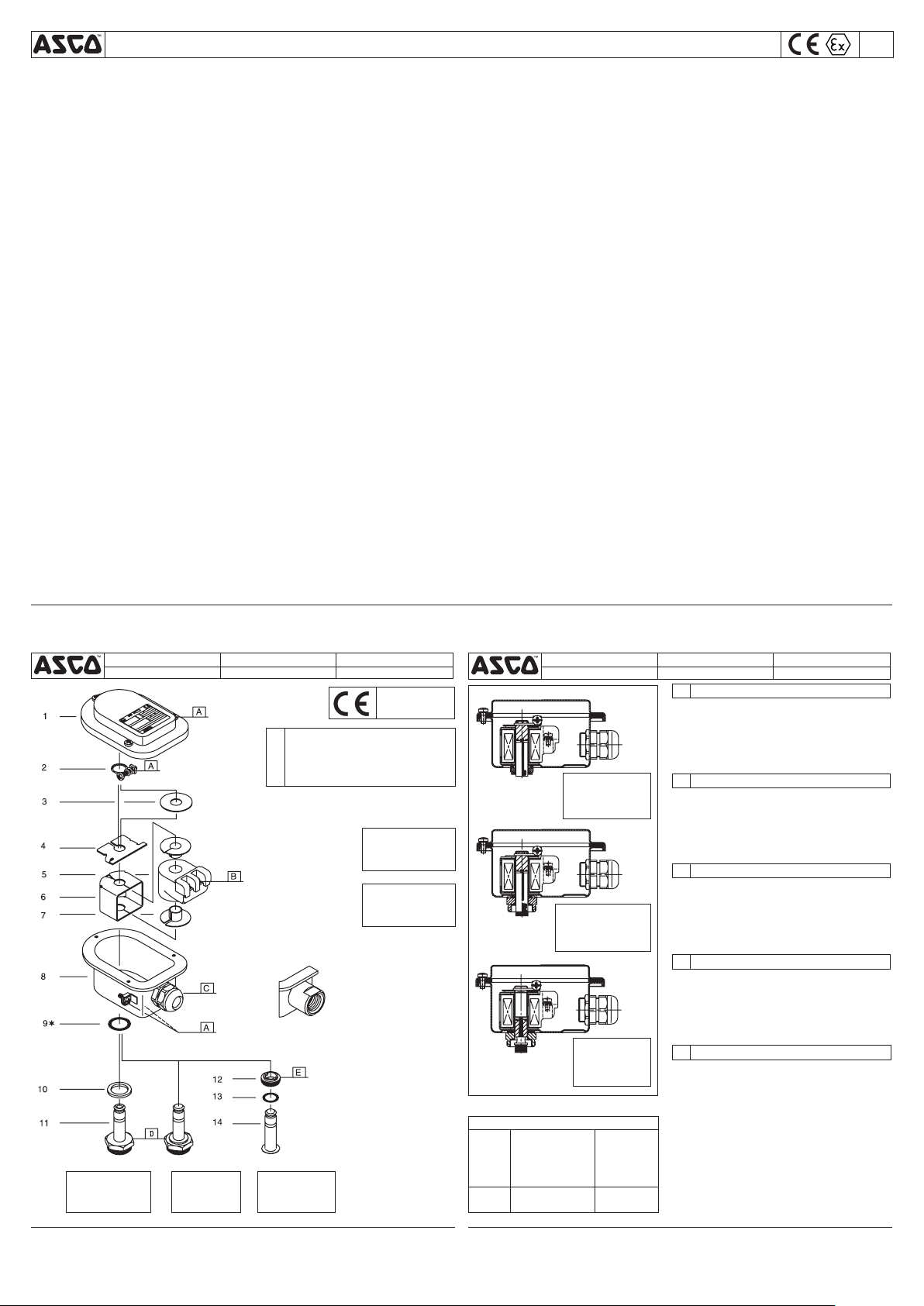
1. Cover assembly
2. Retaining clip
3. Washer
4. Spacer
5. Coil
6. Yok e
7. Sleeve
8. Housing assembly
FR
1. Montage du couvercle
2. Clip de maintien
3. Rondelle élastique
4. Bague d'espacement
5. Bobine
6. Culasse
7. Gaine isolante
8. Montage du boîtier
DE
1. Deckelbaugruppe
2. Klammerhalterung
2/2 PULL TYPE ‑ 15/16
TYPE EXTRACTION 2/2 ‑ 15/16
2/2‑ZUGAUSFÜHRUNG ‑ 15/16
TIPO AD ESTRAZIONE 2/2 ‑ 15/16
2/2 TREK ‑ 15/16
3. Scheibe
4. Distanzstück
5. Magnetspule
6. Joch
7. Hülse
8. Gehäuse
IT
1. Gruppo custodia
2. Clip di fissaggio
3. Rondella
4. Distanziatore
5. Bobina
6. Giogo
7. Manicotto
8. Gruppo sede
NL
1. Deksel
2. Bevestigingsclip
3. Ring
4. Opvulring
5. Spoel
6. Juk
7. Huls
8. Spoelhuis
A
B
C
D
E
2/2 PUSH TYPE
TYPE POUSSOIR 2/2
2/2‑DRUCKAUSFÜHRUNG
TIPO A PRESSIONE 2/2
2/2 DUW
TORQUE CHART
1,5±0,2
0,5±0,1
2±0,2
20±3
10±1
12±2
4±1
17±2
175±25
90±10
ITEMS NEWTON.METRES INCH.POUNDS
ASCO CONTROLS BV
P.O. Box 3, 3925 ZG Scherpenzeel, The Netherlands
Tel. +31(0)33 277 79 11 - Fax +31(0)33 277 45 61 / www.asconumatics.eu
DESCRIPTION
9. Gasket, housing assembly
10. Washer
11. Sol. base sub‑assembly
12. Bonnet
13. O‑ring, bonnet
14. Pnut / ctube assembly
DESCRIPTION
9. Joint d'étanchétié,
montage du boîtier
10. Rondelle élastique
11. Sous‑ensemble de la base
du sol.
12. Couvercle
13. Joint torique, couvercle
14. Montage Pboulon / ctube
BESCHREIBUNG
9. Dichtung, Gehäusebaugruppe
10. Scheibe
11. Haltemutter
12. Ventildeckel
13. Dichtungsring, Ventildeckel
14. Gegenanker‑/
Führungsrohrbaugruppe
DESCRIZIONE
9. Guarnizione, gruppo involucro
10. Rondella
11. Gruppo cannotto solenoide
12. Coperchio
13. Anello di ritenuta, coperchio
14. Gruppo dado/tubo
BESCHRIJVING
9. Afdichting, spoelhuis
10. Ring
11. Kopstuk/deksel‑combinatie
12. Klepdeksel
13. O‑ring, klepdeksel
14. Vaste kern/plunjergang

INSTRUCTIONS D’INSTALLATION ET DE MAINTENANCE
Tête magnétique protection contre la flambée de poussière
Cette feuille d’instructions d’installation et de maintenance du solé‑
noïde constitue un supplément d’ensemble à la feuille particulière
I&M de l’électrovanne. L’identification est effectuée en faisant pré‑
céder le préfixe DU devant le numéro de catalogue. Reportez‑vous
aux feuilles I&M lors de l’installation et de la maintenance de
l’électrovanne valve.
Les électrovannes sont réalisés selon l’annexe II de la Directive
94/9/CE et les normes CENELEC EN 13463‑1, EN 50014 et
EN 50281‑1‑1. Classification II 3D IP67.
Les composants ASCO Numatics sont conçus pour les domaines de
fonctionnement indiqués sur la plaque signalétique ou la documen‑
tation. Aucune modification ne peut être réalisée sur le matériel sans
l’accord préalable du fabricant ou de son représentant. Ces élec‑
trovannes sont conçus afin d’être installés dans des atmosphères
potentiellement explosives, les Groupes II de poussières (Groupe
D, catégorie 3). Le classement de la température d’allumage et de
la température ambiante qui figurent sur la plaque signalétique.
Selon la puissance/température ambiante, il faut utiliser un câble
résistant à la chaleur, convenant à la température indiquée sur la
plaque signalétique.
Le câblage doit être conforme à la réglementation locale et nationale
en matière d’installation d’équipement antidéflagrant. Pour raccorder
les bornes de la bobine, enlever le couvercle du solénoïde. Dénudez
environ 30 mm de l’extrémité de l’isolant extérieur du câble et l’isolant
des fils sur 8 mm. Insérez les câbles dans le presse‑étoupe ou
l’entrée du conduit et raccordez les câbles aux bornes de la bobine.
Raccordez le fil de mise à la terre du câble à la borne interne de la
mise à la terre. Maintenez un certain écart au niveau des fils situés
entre l’entrée du câble et la bobine afin d’éviter toute contrainte
excessive sur les fils. Assemblez le presse‑étoupe et serrez le
joint de compression de l’élastomère de sorte qu’il serre de façon
appropriée le câble. Lorsque le clip/boulon de maintien est dévissé,
il est possible de tourner le solénoïde de 360° pour sélectionner
la position la plus favorable pour l’entrée de câble. Bien serrer le
clip/boulon de maintien et fermer l’enveloppe. Le couvercle de la
tête magnétique est livré avec des raccordements externes pour
conducteur à la terre et de raccordement.
NOTE: LE PRESSE‑ETOUPE STANDARD ACCEPTE DES CABLES
DE DIAMETRE GLOBAL de 7 à 12 mm.
GENERALITES
DESCRIPTION
INSTALLATION
INSTALLATION ELECTRIQUE
(WP/WSDU – M6)
FR
La charge électrique doit être comprise dans la gamme qui figure
sur la plaque signalétique. Tout manquement au respect de la
gamme électrique du classement de la bobine risque d’endom‑
mager la bobine ou de provoquer sa défaillance. Cela annulera
également l’agrément.
Pour éviter tout risque d’accidents ou de détérioration, ne pas
toucher le solénoïde. Il peut produire un fort dégagement thermique
dans des conditions normales de fonctionnement. Si l’électrovanne
est facilement accessible, l’installateur doit prévoir une protection
empêchant tout contact accidentel.
La maintenance dépends des conditions de service. Il est souhaité
de procéder à un nettoyage fréquent, dont l’opportunité dépendra
des conditions de fonctionnement et du milieu ambiant. Lors de l’in‑
tervention, les composants doivent être examinés pour détecter toute
usure excessive. Un ensemble de pièces internes est proposé en
pièces de rechange pour procéder à la réfection. If a problem occurs
during installation/maintenance or in case of doubt please contact
ASCO Numatics or authorize representatives. ATTENTION : Avant
toute opération d’entretien, couper l’alimentation de l’électrovanne,
dépressuriser le corps de la vanne et purger le fluide dans un zone
sécurisée. La tête magnétique doit être entièrement remontée car le
boîtier et les pièces internes complètent le circuit magnétique. En cas
de remplacement de pièces par l’utilisateur, la traçabilité du produit
final ne peut pas être garantie par ASCO Numatics.
Un montage incorrect entraîne l’annulation de l’agrément.
Pour tout renseignement complémentaire, nous vous invitons
à consulter notre site Internet à l’adresse
www.asconumatics.eu
ATTENTION
SERVICE
MAINTENANCE
DECLARATION
BETRIEBSANLEITUNG
Magnetkopf mit Staubzündschutz
Diese Betriebsanleitung für den Magnetkopf ist ein allgemeiner
Nachtrag zur spezifischen Betriebsanleitung für dieses Ventil. Die
Identifizierung erfolgt durch den Vorsatz DU, der der Katalognummer
vorangestellt wird. Bei der Installation und Wartung des Magnetventils
sind immer beide Betriebsanleitungen heranzuziehen.
Die Magnetventile erfüllen die europäische Richtlinie 94/9/
EG Anhang II sowie die Normen EN 13463‑1, EN 50014 und
EN 50281‑1‑1 des Europäischen Komitees für elektrotechnische
Normung (CENELEC) und besitzen die Zulassung nach Zünd‑
schutzart II 3D IP67.
Die ASCO Numatics‑Komponenten dürfen nur innerhalb der auf
den Typenschildern angegebenen Daten eingesetzt werden.
Veränderungen an den Produkten sind nur nach Rücksprache mit
ASCO Numatics zulässig. Diese Magnetventile sind für den Einbau
in Umgebungen mit potentiell explosionsfähigen Atmosphären
der Gruppe II Staube (Gruppe D, Kategorie 3) vorgesehen. Die
Oberflächen temperatur einstufung ist von der auf dem Typenschild
angegebenen Wattzahl und Umgebungstemperatur abhängig. Je
nach Umgebungstemperatur bzw. Wattzahl muß ein hitzebeständiges
Kabel, das für die auf dem Typenschild angegebene Temperatur
geeignet ist, verwendet werden.
Die Verdrahtung muß den örtlichen und nationalen Vorschriften für
exgeschützte Geräte entsprechen. Zum Anschließen an die Spulen‑
klemmen muß der Magnetkopfdeckel abgenommen werden. Äußere
Isolierung des Kabels auf ca. 30 mm und Isolierung der Drähte auf
ca. 8 mm abziehen. Drähte durch die Kabelverschraubung oder den
Kabelanschluß einführen und an die Spulenklemmen anschließen.
Erdungsdraht des Kabels an die interne Erdungsklemme anschlie‑
ßen. Kabelenden zwischen Kabeleinführung und Spule nicht straff
ziehen, um eine übermäßige Zugbeanspruchung an den Kabelenden
zu vermeiden. Kabelverschraubung zusammenbauen und Dichtung
aus Elastomer so anziehen, daß sie das Kabel fest umschließt.
Nach dem Lösen der Klammerhalterung/Sicherungsmutter ist der
Magnetkopf um 360° drehbar, so daß die günstigste Position für
die Kabeleinführung gewählt werden kann. Klammerhalterung/
Sicherungsmutter fest anziehen und Gehäuse schließen. Das
Magnetkopfgehäuse ist mit einer externen Anschlußvorrichtung für
einen Erdungs‑ oder Potentialausgleichsleiter versehen.
HINWEIS: DIE STANDARD‑KABELVERSCHRAUBUNG IST
FÜR KABEL MIT EINEM AUSSENDURCHMESSER von 7 bis
12 mm geeignet.
ALLGEMEINES
BESCHREIBUNG
INSTALLATION
ELEKTRISCHE INSTALLATION
(WP/WSDU – M6)
DE
Die elektrische Belastung muß in dem auf dem Typenschild angege‑
benen Bereich liegen. Wird der elektrische Bereich der Spule nicht
beachtet, so kann dies zur Beschädigung oder zum frühzeitigen
Ausfall der Spule führen. Außerdem erlischt dadurch die Zulassung.
Zur Vermeidung von Personen‑ und Sachschäden sollte jede
Berührung des Magnetkopfs vermieden werden, da dieser unter
normalen Betriebsbedingungen sehr heiß werden kann. Bei leicht
zugänglichem Magnetventil sollte vom Installateur ein Schutz vorge‑
sehen werden, um jegliches versehentliches Berühren zu vermeiden.
Die Wartung hängt von den Betriebsbedingungen ab. Es wird
empfohlen, das Produkt regelmäßig zu reinigen, wobei sich die
Zeitabstände nach dem Medium und den Betriebsbedingungen
richten. Während der Wartung sollten die Komponenten auf
übermäßigen Verschleiß überprüft werden. Für die Überholung
der ASCO Numatics‑Produkte sind komplette Sätze mit internen
Teilen als Ersatzteilsätze erhältlich. Treten Schwierigkeiten bei
Einbau, Betrieb oder Wartung auf sowie bei Unklarheiten, ist mit
ASCO Numatics Rücksprache zu halten. VORSICHT: Vor der
Wartung des Magnetventils muß die Stromversorgung abgeschaltet,
das Ventil drucklos geschaltet und die Flüssigkeit in eine sichere
Zone abgelassen werden. Der Magnetkopf muß wieder vollständig
zusammengebaut werden, da der Magnetkreis durch das Gehäuse
und die internen Teile komplettiert wird. Falls irgendwelche Teile
vom Benutzer ausgetauscht werden, kann ASCO Numatics keine
Garantie für die Rückverfolgbarkeit des Endprodukts übernehmen.
Bei nichtordnungsgemäßer Montage erlischt die Zulassung.
Weitere Informationen finden Sie auf unserer Internet-Site:
www.asconumatics.eu
VORSICHT
BETRIEB
WARTUNG
ERKLÄRUNG
ISTRUZIONI DI INSTALLAZIONE E MANUTENZIONE
Testa magnetica a protezionedall
Questa scheda di installazione e manutenzione della solenoide è
il supplemento generale alla scheda I&M dettagliata per la valvola.
L’identificazione viene realizzata mediante prefisso DU al numero
di catalogo. Per l’installazione e la manutenzione della valvola
solenoide, usare sempre entrambe le schede I&M.
Le elettrovalvole sono state progettate secondo l’Allegato II della
Direttiva europea 94/9/EC e gli standard CENELEC EN 13463‑1,
EN 50014 e EN 50281‑1‑1.
Classificazione II 3D IP67.
Le elettrovalvole ASCO Numatics devono essere utilizzate esclu‑
sivamente rispettando le caratteristiche tecniche specificate sulla
targhetta. Variazioni sulle elettrovalvole sono ammissibili solo dopo
avere consultato il costruttore o il suo rappresentante. Queste
elettrovalvole devono essere installate in atmosfere potenzialmente
esplosive, polveri di Gruppo II (Gruppo D, categoria 3). La classifica‑
zione della temperatura di superficie dipende dal wattaggio e dalla
temperatura ambiente specificate sulla targhetta. A seconda della
temperatura ambiente/wattaggio, occorre usare un cavo resistente
al calore, adatto alla temperatura indicata sulla targhetta.
Il cablaggio deve soddisfare le normative locali e nazionali delle
apparecchiature antideflagranti. Per effettuare la connessione ai
morsetti della bobina, togliere il coperchio della solenoide. Spelare
l’isolante esterno del cavo di circa 30 mm e l’isolante dai conduttori
di 8 mm. Inserire i fili attraverso la tenuta del cavo lo spinotto del
condotto e collegare i connettori ai morsetti della bobina. Collegare
il filo di terra del cavo al morsetto di terra interno. Lasciare un
certo gioco nei conduttori tra l’ingresso del cavo e la bobina onde
evitare un eccessivo stiramento dei conduttori stessi. Montare
la tenuta del cavo e stringere la guarnizione di compressione in
elastomero in modo che aderisca bene attorno al cavo. Una volta
svitata la clip/dado di fissaggio, è possibile ruotare la solenoide di
360° per scegliere la posizione più favorevole per l’ingresso del
cavo. Stringere saldamente la clip/dado di fissaggio e chiudere la
chiusura. La sede della solenoide è munita di raccordo esterno per
conduttore di terra o massa.
NOTA: LA TENUTA DEL CAVO STANDARD ACCETTA CAVI DI
DIAMETRO ESTERNO TOTALE da 7 a 12 mm.
GENERALE
DESCRIZIONE
INSTALLAZIONE
INSTALLAZIONE ELETTRICA
(WP/WSDU – M6)
IT
La potenza elettrica deve rientrare nei valori di targa. Il mancato
rispetto dei valori elettrici della bobina può causare danni o usura
anticipata della bobina stessa. Inoltre, renderà nulla l’approvazione.
Al fine di evitare la possibilità di danni alle persone o alle cose, non
toccare la solenoide. Nelle normali condizioni di funzionamento
potrebbe scaldarsi. Se di facile accesso, l’elettrovalvola deve essere
protetta per evitare qualsiasi contatto accidentale.
La manutenzione dipende dalle condizioni di servizio. Si consiglia una
pulizia periodica, gli intervalli della quale dipendono dai mezzi e dalle
condizioni di servizio. Il ciclo di durata dei componenti dipende dalle
condizioni di funzionamento. In caso di usura è disponibile un set
completo di parti interne per la revisione. Se si incontrano problemi
durante l’installazione e la manutenzione o se si hanno dei dubbi,
consultare ASCO Numatics o i suoi rappresentanti. ATTENZIONE:
Prima di sottoporre ad assistenza la valvola solenoide, spegnere
l’alimentazione, depressurizzare la valvola e far sfiatare il liquido in
una zona sicura. La solenoide deve essere completamente rimontata
in quanto l’involucro e le parti interne completano il circuito magneti‑
co. Nel caso in cui l’utente dovesse effettuare eventuali sostituzioni
di parti, ASCO Numatics non può garantire la rintracciabilità del
prodotto finale. Un errore nell’assemblaggio annullerà l’approvazione.
Per ulteriori informazioni, visitare il nostro sito Internet:
www.asconumatics.eu
ATTENZIONE
SERVIZIO
MANUTENZIONE
DICHIARAZIONE
ALGEMENE INSTALLATIE- EN ONDERHOUDSINSTRUCTIES
Magneetkoppen met beveiliging tegen stofexplosies
Dit installatie‑ en onderhoudsblad van de magneetkop bevat slechts
algemene, aanvullende informatie op het betreffende I&M‑blad van
de afsluiter zelf. Het voorvoegsel DU op het catalogusnummer geeft
het type aan. Raadpleeg altijd beide I&M‑bladen voor het installeren
en onderhouden van de magneetafsluiter.
De magneetafsluiters voldoen aan de normen van Bijlage II van
de Europese Richtlijn 94/9/EG en aan de CENELEC‑normen
EN 13463‑1, EN 50014 en EN 50281‑1‑1. Classificatie II 3D IP67.
ASCO Numatics producten mogen uitsluitend toegepast worden
binnen de op de naamplaat aangegeven specificaties. Wijzigingen
zijn alleen toegestaan na overleg met de fabrikant of haar verte‑
genwoordiger. Deze magneetafsluiters zijn geschikt voor gebruik
in explosiegevaarlijke omgevingen, groep II, stoffen (groep D,
categorie 3). De oppervlakte‑temperatuurklasse is afhankelijk van
het vermogen en de omgevingstemperatuur volgens de gegevens
die op het typeplaatje staan vermeld. Afhankelijk van de omgevings‑
temperatuur en het toegepaste vermogen kan het noodzakelijk zijn
om een hittebestendige kabel te gebruiken, die bestand is tegen de
temperatuur die op het typeplaatje staat vermeld.
De bedrading moet voldoen aan de plaatselijke en nationale
voorschriften voor explosieveilige installaties. Verwijder het mag‑
neetkopdeksel om de spoelaansluitingen te kunnen maken. Verwijder
circa 30 mm van de buitenste isolatiemantel op het uiteinde van de
kabel, en circa 8 mm van de isolatie van de aders. Steek de aders
door de kabel‑ of leidingdoorvoer en sluit de aders op de spoel aan.
Sluit de aardleiding van de kabel aan op de interne aardaansluiting.
Zorg ervoor dat de aders voldoende speling hebben tussen het
kabelinvoerpunt en de spoelaansluitingen, om te voorkomen dat er
mechanische spanning op de aders kan komen te staan. Monteer
de kabeldoorvoer en draai de drukmoer voldoende vast om de
flexibele afdichting strak om de kabel te klemmen. Draai de moer
van de bevestigingsclip los zodat de magneetkop 360° kan draaien
en draai de magneetkop naar de meest gunstige positie gelet op
de kabeldoorvoer. Draai de moer van de bevestigingsclip stevig vast
en maak het huis dicht. Het spoelhuis is voorzien van een extern
aansluitpunt voor een aard‑ of massaleiding.
OPMERKING: DE STANDAARD‑KABELDOORVOER IS GE‑
SCHIKT VOOR KABELS MET EEN UITWENDIGE DIAMETER
tussen 7 en 12 mm.
ALGEMEEN
BESCHRIJVING
INSTALLATIE
ELEKTRISCHE INSTALLATIE
(WP/WSDU – M6))
NL
De elektrische belasting mag niet hoger zijn dan op het typeplaatje
staat vermeld. Het overschrijden van het elektrisch vermogen van
de spoel veroorzaakt schade en bekort de levensduur van de spoel.
Ook vervalt in dat geval de typegoedkeuring.
Raak de magneetkop niet aan, dit voorkomt persoonlijk letsel en
beschadiging van de apparatuur. Ook bij normaal gebruik kan de
apparatuur heet worden. In voorkomende gevallen dient men de
spoel af te schermen voor aanraking.
Het onderhoud is afhankelijk van de bedrijfsomstandigheden. We
raden u aan om het product regelmatig te reinigen, in intervallen
die afhankelijk zijn van het medium en de mate van onderhoud.
Controleer tijdens het onderhoud of onderdelen zijn versleten. In
geval van slijtage zijn reserve‑onderdelensets beschikbaar om een
inwendige revisie uit te voeren. In geval van problemen of als er
onduidelijkheden tijdens montage, gebruik of onderhoud optreden,
dan dient men zich tot ASCO Numatics of haar vertegenwoordiger
te wenden. LET OP: Voordat u begint aan onderhoudswerk moet u
de elektrische voeding uitschakelen, de afsluiter drukloos maken en
het medium naar een veilige ruimte afvoeren. Alle onderdelen van
de magneetkop moeten worden gemonteerd, omdat het huis en de
inwendige onderdelen deel uitmaken van het magnetisch circuit. Ver‑
vangt u zelf onderdelen, dan kan ASCO Numatics niet instaan voor
de resultaten. Door onjuiste montage vervalt de typegoedkeuring.
Ga voor meer informatie naar onze website:
www.asconumatics.eu
LET OP
GEBRUIK
ONDERHOUD
VERKLARING
123620‑161X
IM1047‑21A‑X / pg. 2
ASCO CONTROLS BV
P.O. Box 3, 3925 ZG Scherpenzeel, The Netherlands
Tel. +31(0)33 277 79 11 - Fax +31(0)33 277 45 61 / www.asconumatics.eu
 Loading...