

This installation and maintenance instruc-
GENERAL
tion sheet of the solenoid is a general supplement to the particular I&M sheet for the
valve. The identification is made by prefix IS
to the catalogue number. Always use both
I&M sheets for installing and maintaining
the solenoid valve.
DESCRIPTION
The solenoid valves are designed in accordance with Annex II of the European Directive
94/9/EC and IEC standards EN 13463-1,
EN-IEC 60079-0, EN-IEC 60079-11,
EN-IEC 60079-26, EN-IEC 61241-0 and
EN-IEC 61241-11.
Classification: II 2G/Ga Ex ia IIC / Ex iaD 21
IP65.
INSTALLATION
ASCO Numatics components are intended
to be used only within the technical characteristics as specified on the nameplate.
Changes to the equipment are only allowed after consulting the manufacturer or
its representative. These solenoid valves
are intended for installation in potentially
explosive atmospheres, Groups II A, II B or
II C gases, vapors, mists or dusts (Group
G/D, category 2). The surface temperature
classification is T6/85°C.
ELECTRICAL INSTALLATION
Wiring must comply with local and national
regulations of explosion proof equipment.
Application of the IS solenoid in the hazardous area is not permitted without the
addition of an approved and classified
device (such as barriers), located between
the safe and the hazardous area. The
purpose of the safety device is to protect
the equipment located within the hazardous area from current and voltage surges,
INSTALLATION AND MAINTENANCE INSTRUCTIONS
Intrinsically safe/low power solenoid operator (ISSC – MXX)
which might enter the system from the
energy sources located in the safe area.
In addition the wiring to the equipment
installed within the hazardous location
should satisfy particular requirements with
respect to resistance (R), inductance (L),
capacitance (C), inductance to resistance
ratio (L/R) and screening. Due to redundant blocking diodes the effective internal
inductance and capacitance of the solenoid
are neglibly small. To make the electrical
connection to the spade plug connector,
strip the outer insulation of the cable back
over approximately 30 mm and the insulation from the leads over 5 mm. Select the
proper sealing ring Ø 6-8 mm or Ø 8-10 mm
depending on cable diameter. Insert cable
through the compression screw, washer,
sealing ring and connector housing and
connect wires to the terminal block. Place
terminal block into connector housing and
assemble connector cover. Note that the
cover must be pressed properly to the connector until a ‘click’ is heard. The terminal
block can be mounted in four different positions to select the most favourable position
for the cable entry. Assemble the sealing
ring, washer and tighten the compression
screw into the connector housing in such
a manner that the seal fits tightly around
the cable. Position connector gasket, place
connector over coil spades and tighten the
central screw to specified torque to ensure
proper gaskets compression. The coil itself
can be rotated 360° to select the most favourable position for the cable entry.
ELECTRICAL SPECIFICATIONS
Nominal operating voltage range:
24 VDC +/- 10%.
Minimum series resistance required:
200 Ohms.
Maximum allowable system leakage current: 1 mA.
Intrinsically Safe Coil Calculations
The following application information will
allow the calculation of the loop current for
the ASCO intrinsically safe solenoid.
Definitions:
The supply voltage to the
V
supply
barrier.
The ambient temperature
T
ambient
in degrees C.
The maximum barrier end to
R
barrier
end resistance.
The maximum resistance in
R
loop
lead wire
The resistance of the solenoid
R
coil
coil at Tambient
= 104 Ω
R
coil
Loop current in the circuit:
I
loop
=
I
loop
This current must always be greater than or
equal to 28mA for proper operation fo the
solenoid valve.
CAUTION
Electrical load must be within the range
stated on the nameplate. Failure to stay
within the electrical range of the coil rating
results in damage to or premature failure of
the coil. It will also invalidate the approval.
r
q
GB
SERVICE
To prevent the possibility of personal or
property damage, do not touch the solenoid.
It can become hot under normal operation
conditions. If the solenoid valve is easily accessible, the installer must provide
protection preventing accidental contact.
To prevent electrostatic hazard, clean coil
surface only with a damp cloth. Do not use
solvents.
MAINTENANCE
Maintenance depends on service conditions. Periodic cleaning is recommended,
the timing of which will depend on the
media and service conditions. During servicing, components should be examined for
excessive wear. A complete set of internal
parts is available as a spare parts kit. If a
problem occurs during installation/maintenance or in case of doubt please contact
ASCO Numatics or authorize representatives.
CAUTION: Before servicing the solenoid
valve, turn off electrical power, depressurize
valve and vent fluid to a safe area.
Solenoid must be fully reassembled as the
housing and internal parts complete the
magnetic circuit. In case of any replacement of parts by the user, the traceability
of the final product can not be guaranteed
by ASCO Numatics. Wrong assembly will
invalidate the approval.
For additional information visit our internet site: www.asconumatics.eu
123620-292X
IM1050-21B-X-R0 / pg. 1
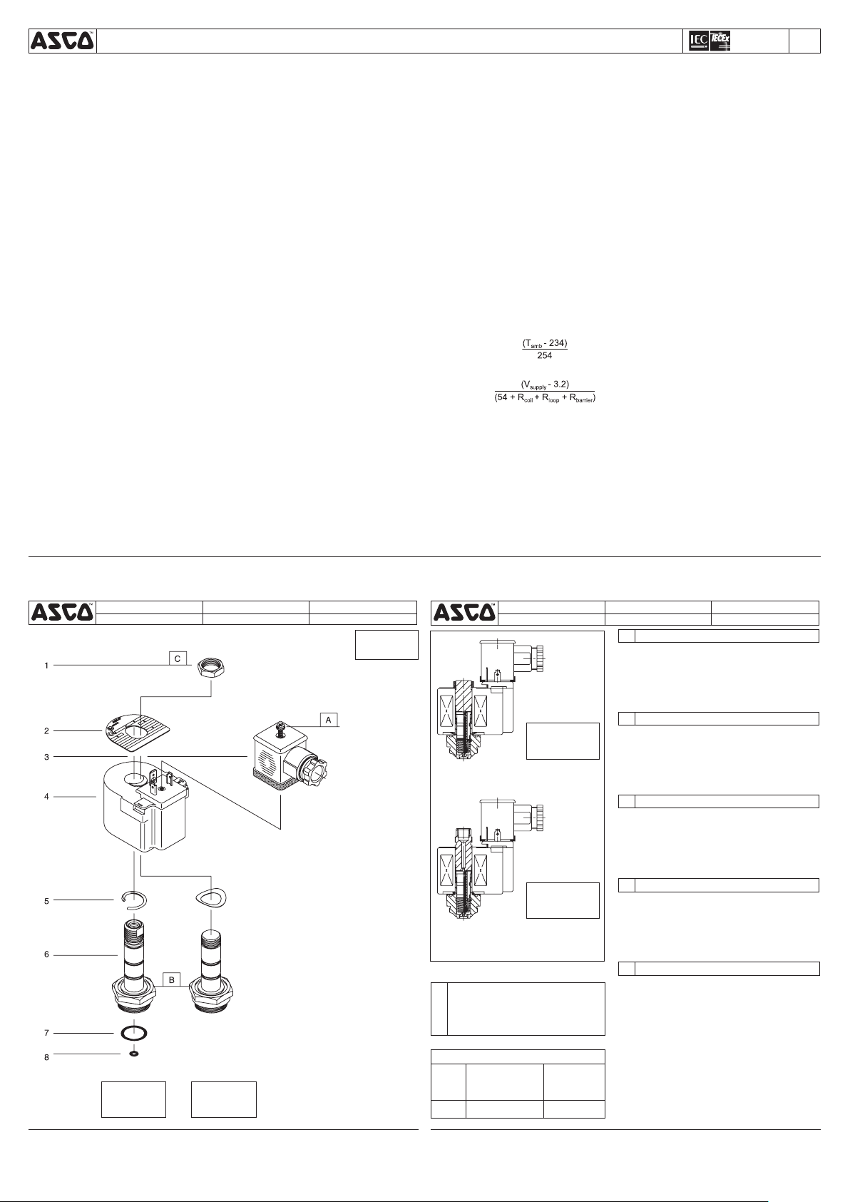
DRAWING DESSIN ZEICHNUNG
DISEGNO TEKENING
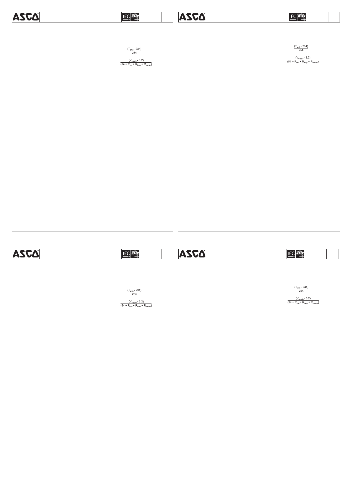
3/2 PULL TYPE
TYPE EXTRACTION 3/2
3/2-ZUGAUSFÜHRUNG
TIPO AD ESTRAZIONE 2/2
3/2 TREK
2/2 PULL TYPE
TYPE EXTRACTION 2/2
2/2-ZUGAUSFÜHRUNG
TIPO AD ESTRAZIONE 2/2
2/2 TREK
SERIES
ISSC-MXX
DRAWING DESSIN ZEICHNUNG
DISEGNO TEKENING
GB
1. Nut
2. Nameplate, retaining
3. Connector assembly
4. Coil
5. Washer, spring
6. Cartridge assembly
7. O-ring, cartridge
8. O-ring, seat
3/2 PULL TYPE
TYPE EXTRACTION 3/2
3/2-ZUGAUSFÜHRUNG
TIPO AD ESTRAZIONE 2/2
3/2 TREK
2/2 PULL TYPE
TYPE EXTRACTION 2/2
2/2-ZUGAUSFÜHRUNG
TIPO AD ESTRAZIONE 2/2
2/2 TREK
GB
Supplied in spare part kit
FR
Livrées en pochette de rechange
DE
Enthalten im Ersatzteilsatz
IT
Disponibile nel Kit parti di ricambio
NL
Geleverd in vervangingsset
TORQUE CHART
A
B
C
ITEMS NEWTON.METRES INCH.POUNDS
ASCO CONTROLS BV
P.O. Box 3, 3925 ZG Scherpenzeel, The Netherlands
Tel. +31(0)33 277 79 11 - Fax +31(0)33 277 45 61 / www.asconumatics.eu
0,6±0,2
20±3
1,1±0,1
5±2
175±25
10±1
FR
1. Ecrou
2. Plaque signalétique,
maintien
3. Montage du connecteur
4. Bobine
5. Rondelle élastique, ressort
6. Montage de la cartouche
7. Joint torique, cartouche
8. Joint torique, siège
DE
1. Mutter
2. Typenschild, Halter
3. Gerätesteckdose
4. Magnetspule
5. Federscheibe
6. Einsatzbaugruppe
7. Dichtungsring, Einsatz
8. Dichtungsring, Ventilsitz
IT
1. Dado
2. Targhetta / di tenuta
3. Gruppo connettore
4. Bobina
5. Rondella, molla
6. Gruppo cartuccia
7. Anello di ritenuta, cartuccia
8. Anello di ritenuta, sede
NL
1. Moer
2. Bevestigingstypeplaatje
3. Steker
4. Spoel
5. Veerring
6. Cartridge
7. O-ring, cartridge
8. O-ring, klepzitting
DESCRIPTION
DESCRIPTION
BESCHREIBUNG
DESCRIZIONE
BESCHRIJVING
INSTRUCTIONS D’INSTALLATION ET DE MAINTENANCE
Tête magnétique à tension basse/renforcée intrinsèquement
Cette feuille d’instructions d’installation et de maintenance du
solénoïde constitue un supplément d’ensemble à la feuille particulière I&M de l’électrovanne. L’identification est effectuée en faisant
précéder le préfixe IS devant le numéro de catalogue. Reportezvous aux feuilles I&M lors de l’installation et de la maintenance de
l’électrovanne valve.
Les têtes électrovannes sont conformes l’Annexe II de la Directive
européenne 94/9/CE et les normes EN 13463-1, EN-IEC 60079-0,
EN-IEC 60079-11, EN-IEC 60079-26, EN-IEC 61241-0 et
EN-IEC 61241-11 du IEC. Classification: II 2G/Ga Ex ia IIC / Ex iaD 21
IP65.
Les composants ASCO Numatics sont conçus pour les domaines
de fonctionnement indiqués sur la plaque signalétique ou la documentation. Aucune modification ne peut être réalisée sur le matériel
sans l’accord préalable du fabricant ou de son représentant. Ces
électrovannes sont conçus afin d’être installés dans des atmosphères potentiellement explosives, les Groupes II A, II B ou II C de
gaz, vapeurs, brumes ou poussières (Groupe G/D, catégorie 2). Le
classement de la température d’allumage est T6/85°C.
Le câblage doit être conforme à la réglementation locale et nationale
en matière d’installation d’équipement antidéflagrant. L’application
du solénoïde IS dans la zone à risque n’est pas autorisée sans avoir
placé préalablement un équipement agréé et classé (tel que des
barrières), situé entre la zone sécurisée et la zone à risque. L’objectif
de l’équipement de sécurité vise à protéger les appareils placés dans
la zone à risque contre tout courant transitoire anormal et surtension,
qui pourrait pénétrer dans le système depuis les sources d’énergie
situées dans la zone sécurisée. En outre, le câblage effectué sur
l’équipement installé dans la zone à risque devrait respecter des
exigences particulières relatives à la résistance (R), l’inductance (L),
la capacitance (C), l’inductance au ratio de résistance (L/R) et le
filtrage. Grâce à des diodes de blocage redondantes, l’inductance
et la capacitance interne effective du solénoïde sont très faibles.
Pour effectuer le raccordement électrique au connecteur, dénudez
environ 30 mm du câble de l’isolant extérieur et l’isolant des fils sur
5 mm. Sélectionnez le joint d’étanchéité approprié Ø 6-8 mm ou
Ø 8-10 mm selon le diamètre du câble. Insérez le câble dans la vis
de compression, la rondelle, le joint d’étanchéité et le boîtier du
connecteur, puis raccordez les fils au bloc de la borne. Placez le bloc
des bornes dans le boîtier du connecteur et assemblez le couvercle
du connecteur. Veuillez noter qu’il convient d’enfoncer correctement
le couvercle sur le connecteur jusqu’à ce qu’un ‘clic’soit audible.
Le bloc des bornes peut être installé dans 4 positions différentes
afin de sélectionner la position qui convient le mieux à l’entrée de
câble. Assemblez le joint d’étanchéité, la rondelle et serrez la vis
de compression dans le boîtier du connecteur de manière à ce
que le joint s’adapte autour du câble. Placez le joint d’étanchéité
du connecteur, placez le connecteur sur les lames de la bobine et
serrez la vis centrale en fonction du schéma de couple afin d’assurer
la compression adéquate des joints d’étanchéité. Il est possible de
tourner la bobine elle-même de 360° pour sélectionner la position
la plus favorable pour l’entrée de câble.
CARACTERISTIQUES TECHNIQUES ELECTRIQUES
Gamme de tension nominale de fonctionnement:
24 VCC +/- 10%.
Résistance série minimum exigée: 200 Ohms.
Courant de fuite du système admissible maximum: 1 mA.
Calculs de bobine intrinsèquement sécurisés
GENERALITES
DESCRIPTION
MONTAGE
INSTALLATION ELECTRIQUE
(ISSC – MXX)
r
Les informations suivantes sur l’application permettent le calcul
du courant de boucle pour le solénoïde intrinsèquement sécurisé.
Définitions:
V
La tension d’alimentation vers la barrière.
supply
T
La température ambiante en degrés C.
ambient
R
La résistance de bout en bout maximum
barrier
de la barrière.
R
La résistance maximum du fil de plomb
loop
R
La résistance de la bobine de l’électrovanne
coil
à T
R
= 104 Ω
coil
I
Courant de boucle dans le circuit:
loop
I
=
loop
Ce courant doit toujours être égal ou supérieur à 28mA pour un
fonctionnement correct de l’électrovanne.
La charge électrique doit être comprise dans la gamme qui figure
sur la plaque signalétique. Tout manquement au respect de la
gamme électrique du classement de la bobine risque d’endommager la bobine ou de provoquer sa défaillance. Cela annulera
également l’agrément.
Pour éviter tout risque d’accidents ou de détérioration, ne pas
toucher le solénoïde. Il peut produire un fort dégagement thermique
dans des conditions normales de fonctionnement. Si l’électrovanne
est facilement accessible, l’installateur doit prévoir une protection
empêchant tout contact accidentel. Pour éviter tout risque d’électricité
statique, nettoyez la surface de la bobine uniquement à l’aide d’un
chiffon humide. Ne pas utiliser de solvants.
La maintenance dépends des conditions de service. Il est souhaitable de procéder à un nettoyage périodique dont l’intervalle varie
suivant la nature du fluide, les conditions de fonctionnement et le
milieu ambiant. Lors de l’intervention, les composants doivent être
examinés pour détecter toute usure excessive. Un ensemble de
pièces internes est proposé en pièces de rechange pour procéder
à la réfection. If a problem occurs during installation/maintenance
or in case of doubt please contact ASCO Numatics or authorize
representatives.
ATTENTION : Avant toute opération d’entretien, couper l’alimentation de l’électrovanne, dépressuriser le corps de la vanne et
purger le fluide dans un zone sécurisée. La tête magnétique doit
être entièrement remontée car le boîtier et les pièces internes
complètent le circuit magnétique. En cas de remplacement de
pièces par l’utilisateur, la traçabilité du produit final ne peut pas
être garantie par ASCO Numatics. Un montage incorrect entraîne
l’annulation de l’agrément.
Pour toute information complémentaire, veuillez consulter notre
site Internet: www.asconumatics.fr
ambient
ATTENTION
FONCTIONNEMENT
ENTRETIEN
q
FR
BETRIEBSANLEITUNG
Erhöhte Sicherheit / Vergußgekapselter Magnetkopf
Diese Betriebsanleitung für den Magnetkopf ist ein allgemeiner
Nachtrag zur spezifischen Betriebsanleitung für dieses Ventil. Die
Identifizierung erfolgt durch den Vorsatz IS, der der Katalognummer
vorangestellt wird. Bei der Installation und Wartung des Magnetventils
sind immer beide Betriebsanleitungen heranzuziehen.
Die Magnetventile erfüllen die europäische Richtlinie 94/9/EG
Anhang II sowie die Normen EN 13463-1, EN-IEC 60079-0,
EN-IEC 60079-11, EN-IEC 60079-26, EN-IEC 61241-0 und
EN-IEC 61241-11 des IEC und besitzen die Zulassung von KEMA
(Niederlande) nach Zündschutzart: II 2G/Ga Ex ia IIC / Ex iaD 21
IP65.
Die ASCO Numatics-Komponenten dürfen nur innerhalb der auf
den Typenschildern angegebenen Daten eingesetzt werden.
Veränderungen an den Produkten sind nur nach Rücksprache mit
ASCO Numatics zulässig. Diese Magnetventile sind für den Einbau in
Umgebungen mit potentiell explosionsfähigen Atmosphären, Gasen,
Dämpfen und Staube der Gruppe IIA, IIB oder IIC (Gruppe G/D,
Kategorie 2) vorgesehen. Die Oberflächen-temperatureinstufung
ist T6/85°C.
Die Verdrahtung muß den örtlichen und nationalen Vorschriften für
exgeschützte Geräte entsprechen. Der Einsatz des Magnetkopfs
IS in gefährlichen Zonen ist nur durch zusätzlichen Einbau einer
zugelassenen und klassifizierten Vorrichtung (wie z.B. Barrieren)
zwischen der sicheren und der gefährlichen Zone zulässig. Zweck
der Sicherheitsvorrichtung ist es, das in der gefährlichen Zone
angeordnete Gerät vor Strom- und Spannungsstößen zu schützen,
die eventuell ausgehend von den in der sicheren Zone angeordneten
Energiequellen auf das System einwirken. Darüber hinaus muß die
Verdrahtung zu dem in der gefährlichen Zone installierten Gerät
spezielle Anforderungen in bezug auf Widerstand (R), Induktivität (L),
Kapazität (C), Verhältnis zwischen Induktivität und Widerstand (L/R)
und Abschirmung erfüllen. Aufgrund der redundanten Sperrdioden
ist die effektive interne Induktivität und Kapazität des Magnetskopfs
vernachlässigbar gering. Zum Anschließen an die Gerätesteckdose
äußere Isolierung des Kabels auf ca. 30 mm und Isolierung der
Kabelenden auf 5 mm abziehen. Passenden Dichtungsring mit
Ø 6-8 mm oder Ø 8-10 mm je nach Kabeldurchmesser wählen.
Kabel durch Druckschraube, Scheibe, Dichtungsring und Gerätesteckdosengehäuse führen und Drähte an die Klemmenleiste
anschließen. Klemmenleiste in das Gerätesteckdosengehäuse
einbauen und Gehäusedeckel schließen. Darauf achten, daß der
Gehäusedeckel beim Schließen hörbar einrastet. Die Klemmenleiste
kann in vier verschiedenen Positionen eingebaut werden, so daß
die günstigste Position für die Kabeleinführung gewählt werden
kann. Dichtungsring und Scheibe montieren und Druckschraube
in dem Gerätesteckdosengehäuse anziehen, so daß die Dichtung
das Kabel fest umschließt. Gerätesteckdosendichtung anbringen,
Gerätesteckdose auf die Spulenflachstecker aufsetzen und Schraube
in der Mitte mit dem angegebenen Drehmoment anziehen, um einen
korrekten Dichtungsdruck zu gewährleisten. Die Spule ist um 360
Grad drehbar, so daß die günstigste Position für die Kabeleinführung
gewählt werden kann.
Nennbetriebsspannungsbereich: 24 V= +/- 10%.
Erforderlicher Mindestreihenwiderstand: 200 Ohm.
Maximal zulässiger Systemleckstrom: 1 mA.
Berechnung der eigensicheren Spule
Anhand der folgenden Anwendungsdaten kann der Schleifenstrom
für den eigensicheren ASCO Magnetkopf ermittelt werden.
ALLGEMEINES
BESCHREIBUNG
EINBAU
ELEKTRISCHE INSTALLATION
ANSCHLUSSWERTE
(ISSC – MXX)
r
Definitionen:
V
Versorgungsspannung zur Barriere.
supply
T
Umgebungstemperatur in Grad Celsius.
ambient
R
Maximaler End-zu-End-Widerstand der
barrier
Barriere.
R
Maximaler Widerstand des Kabeldrahts.
loop
R
Widerstand der Magnetspule bei Tambient
coil
R
= 104Ω
coil
I
Schleifenstrom im Stromkreis:
loop
I
=
loop
Dieser Strom muß immer größer als oder gleich 28 mA sein,
um einen korrekten Betrieb des Magnetventils zu gewährleisten.
Die elektrische Belastung muß in dem auf dem Typenschild angegebenen Bereich liegen. Wird der elektrische Bereich der Spule nicht
beachtet, so kann dies zur Beschädigung oder zum frühzeitigen
Ausfall der Spule führen. Außerdem erlischt dadurch die Zulassung.
Zur Vermeidung von Personen- und Sachschäden sollte jede
Berührung des Magnetkopfs vermieden werden, da dieser unter
normalen Betriebsbedingungen sehr heiß werden kann. Bei leicht
zugänglichem Magnetventil sollte vom Installateur ein Schutz
vorgesehen werden, um jegliches versehentliches Berühren zu
vermeiden. Zur Vermeidung von elektrostatischer Entladung sollte
die Spulenoberfläche nur mit einem feuchten Tuch gereinigt werden.
Keinesfalls Lösungsmittel verwenden.
Die Wartung hängt von den Betriebsbedingungen ab. Es wird
empfohlen, das Produkt regelmäßig zu reinigen, wobei sich die
Zeitabstände nach dem Medium und den Betriebsbedingungen
richten. Während der Wartung sollten die Komponenten auf
übermäßigen Verschleiß überprüft werden. Für die Überholung
der ASCO Numatics-Produkte sind komplette Sätze mit internen
Teilen als Ersatzteilsätze erhältlich. Treten Schwierigkeiten bei
Einbau, Betrieb oder Wartung auf sowie bei Unklarheiten, ist mit
ASCO Numatics Rücksprache zu halten.
VORSICHT: Vor der Wartung des Magnetventils muß die Stromversorgung abgeschaltet, das Ventil drucklos geschaltet und die
Flüssigkeit in eine sichere Zone abgelassen werden. Der Magnetkopf
muß wieder vollständig zusammengebaut werden, da der Magnetkreis durch das Gehäuse und die internen Teile komplettiert wird.
Falls irgendwelche Teile vom Benutzer ausgetauscht werden, kann
ASCO Numatics keine Garantie für die Rückverfolgbarkeit des
Endprodukts übernehmen. Bei nichtordnungsgemäßer Montage
erlischt die Zulassung.
Weitere Informationen finden Sie auf unserer Internet-Site:
www.asconumatics.de
VORSICHT
BETRIEB
WARTUNG
q
DE
ISTRUZIONI DI INSTALLAZIONE E MANUTENZIONE
Testa magnetica a sicurezza intrinseca e basso consumo
Questa scheda di installazione e manutenzione della solenoide è il
supplemento generale alla scheda I & M dettagliata per la valvola.
L’identificazione viene realizzata mediante prefisso IS al numero
di catalogo. Per l’installazione e la manutenzione della valvola
solenoide, usare sempre entrambe le schede I&M.
Le elettrovalvole sono state progettate secondo l’Allegato II
della Direttiva europea 94/9/EC e gli standard IEC EN 13463-1,
EN-IEC 60079-0, EN-IEC 60079-11, EN-IEC 60079-26,
EN-IEC 61241-0 ed EN-IEC 61241-11.
Classificazione: II 2G/Ga Ex ia IIC / Ex iaD 21 IP65.
Le elettrovalvole ASCO Numatics devono essere utilizzate esclusivamente rispettando le caratteristiche tecniche specificate sulla
targhetta. Variazioni sulle elettrovalvole sono ammissibili solo dopo
avere consultato il costruttore o il suo rappresentante. Queste
elettrovalvole devono essere installate in atmosfere potenzialmente
esplosive, gas, vapori, nebbie o polveri di Gruppo IIA, IIB o IIC
(Gruppo G/D, categoria 2). La classificazione della temperatura di
superficie è T6/85°C.
Il cablaggio deve soddisfare le normative locali e nazionali delle
apparecchiature antideflagranti. L’applicazione della solenoide IS
in zone a rischio non è consentita senza l’aggiunta di un dispositivo
approvato e classificato (tipo barriere), posto tra la zona sicura e
quella a rischio. Lo scopo del dispositivo di sicurezza è quello di
proteggere le apparecchiature che si trovano nella zona a rischio da
sovracorrenti che potrebbero entrare nell’impianto dalle sorgenti di
energia che si trovano nella zona sicura. Inoltre, il cablaggio delle apparecchiature installate nell’ambito della postazione a rischio devono
rispettare particolari requisiti in quanto a resistenza (R), induttanza
(L), capacitanza (C), induttanza al rapporto di resistenza (L/R) e
schermaggio. A causa dei diodi di bloccaggio ridondanti, l’induttanza
interna effettiva e la capacitanza della solenoide sono trascurabili.
Per realizzare la connessione elettrica al connettore a spina a lancia,
spelare l’isolante esterno del cavo di circa 30 mm e l’isolante dai
conduttori di 5 mm. Selezionare l’anello di ritenuta corretto di Ø 6-8
mm o Ø 8-10 mm a seconda del diametro del cavo Inserire il cavo
attraverso la vite a compressione, la rondella, l’anello di tenuta e la
sede del connettore e collegare i fili alla morsettiera. Collocare la
morsettiera nella sede del connettore e montare relativo coperchio.
Notare che il coperchio deve essere correttamente premuto sul
connettore fino a che non si senta uno scatto. È possibile montare
la morsettiera in quattro diverse posizioni per selezionare quella più
favorevole all’ingresso del cavo. Montare l’anello di tenuta, la rondella
e stringere la vite a compressione nella sede del connettore in modo
che la guarnizione aderisca attorno al cavo. Collocare la guarnizione
del connettore, posizionare il connettore sulle forcelle della bobina e
stringere la vite centrale secondo la coppia specificata per garantire
la corretta compressione delle guarnizioni. La bobina può essere
ruotata di 360 gradi per selezionare la posizione più favorevole per
l’ingresso del cavo.
Range di tensione di funzionamento nominale: 24 VDC +/- 10%.
Resistenza di serie minima richiesta: 200 Ohm.
Corrente di dispersione max. ammessa dal sistema: 1 mA.
Calcoli della bobina a sicurezza intrinseca
Le seguenti informazioni sull’applicazione consentiranno i calcoli della corrente di circuito per la solenoide a sicurezza intrinseca ASCO.
GENERALE
DESCRIZIONE
INSTALLAZIONE
INSTALLAZIONE ELETTRICA
SPECIFICHE ELETTRICHE
(ISSC – MXX)
r
Definizioni:
V
La tensione di alimentazione alla barriera.
supply
T
La temperatura ambiente espressa in gradi
ambient
centigradi.
R
La massima resistenza della barriera da
barrier
un’estremità all’altra.
R
La massima resistenza nel conduttore.
loop
R
La resistenza della bobina solenoide a
coil
T
R
= 104 Ω
coil
I
Corrente di circuito:
loop
I
=
loop
Per il corretto funzionamento della valvola solenoide, occorre che
questa corrente sia sempre superiore o uguale a 28mA.
La potenza elettrica deve rientrare nei valori di targa. Il mancato
rispetto dei valori elettrici della bobina può causare danni o usura
anticipata della bobina stessa. Inoltre, renderà nulla l’approvazione.
Al fine di evitare la possibilità di danni alle persone o alle cose, non
toccare la solenoide. Nelle normali condizioni di funzionamento
potrebbe scaldarsi. Se di facile accesso, l’elettrovalvola deve
essere protetta per evitare qualsiasi contatto accidentale. Al fine di
evitare rischi elettrostatici, pulire la superficie della bobina usando
esclusivamente un panno umido. Non usare solventi.
La manutenzione dipende dalle condizioni di servizio. Questi
componenti devono essere puliti periodicamente. Il tempo che
intercorre tra una pulizia e l’altra varia a seconda delle condizioni
di funzionamento. Il ciclo di durata dei componenti dipende dalle
condizioni di funzionamento. In caso di usura è disponibile un set
completo di parti interne per la revisione. Se si incontrano problemi
durante l’installazione e la manutenzione o se si hanno dei dubbi,
consultare ASCO Numatics o i suoi rappresentanti.
ATTENZIONE: Prima di sottoporre ad assistenza la valvola solenoide, spegnere l’alimentazione, depressurizzare la valvola e far
sfiatare il liquido in una zona sicura. La solenoide deve essere
completamente rimontata in quanto l’involucro e le parti interne
completano il circuito magnetico. Nel caso in cui l’utente dovesse
effettuare eventuali sostituzioni di parti, ASCO Numatics non può
garantire la rintracciabilità del prodotto finale. Un errore nell’assemblaggio annullerà l’approvazione.
Per informazioni aggiuntive, visitate il nostro sito Internet:
www.asconumatics.it
ambient
ATTENZIONE
SERVIZIO
MANUTENZIONE
q
IT
ALGEMENE INSTALLATIE- EN ONDERHOUDSINSTRUCTIES
Verhoogde veiligheid / ingekapselde magneetkop
Dit installatie- en onderhoudsblad van de magneetkop bevat slechts
algemene, aanvullende informatie op het betreffende I&M-blad van
de afsluiter zelf. Het voorvoegsel IS op het catalogusnummer geeft
het type aan. Raadpleeg altijd beide I&M-bladen voor het installeren
en onderhouden van de magneetafsluiter.
De magneetafsluiters voldoen aan de normen van Bijlage II
van de Europese Richtlijn 94/9/EEG en aan de IEC-normen
EN 13463-1, EN-IEC 60079-0, EN-IEC 60079-11, EN-IEC 60079-26,
EN-IEC 61241-0 en EN-IEC 61241-11.
Classificatie: II 2G/Ga Ex ia IIC / Ex iaD 21 IP65.
ASCO Numatics producten mogen uitsluitend toegepast worden
binnen de op de naamplaat aangegeven specificaties. Wijzigingen
zijn alleen toegestaan na overleg met de fabrikant of haar vertegenwoordiger. Deze magneetafsluiters zijn geschikt voor gebruik in
explosiegevaarlijke omgevingen, groepen II A, II B en II C, gassen,
dampen, nevels en stoffen (groep G/D, categorie 2). De oppervlaktetemperatuurklasse is T6/85°C.
De bedrading moet voldoen aan de plaatselijke en nationale
voorschriften voor explosieveilige installaties. IS-magneetkoppen
moeten worden aangesloten op een specifieke en gehomologeerde
elektrische voeding (via een barrière of interface) die is geïnstalleerd
in een ongevaarlijke zone. Het doel van deze beveiliging is het voorkomen van stroom- en spanningspieken in de explosiegevaarlijke
omgeving, afkomstig van de voeding die zich in de ongevaarlijke zone
bevindt. Bovendien moet de bedradingswijze van de apparatuur in
de explosiegevaarlijke omgeving voldoen aan specifieke normen
voor weerstand (R), zelfinductie (L), elektrische capaciteit (C), de
verhouding tussen zelfinductie en weerstand (L/R) en afscherming.
Door toepassing van redundante sperdiodes zijn de effectieve
interne zelfinductie en de elektrische capaciteit van de magneetkop
verwaarloosbaar klein. Verwijder voor steker-aansluitingen circa 30
mm van de buitenste isolatiemantel op het uiteinde van de kabel,
en circa 5 mm van de isolatie van de ader. Gebruik het juiste type
afdichtingsring Ø 6-8 mm of Ø 8-10 mm afhankelijk van de diameter
van de kabel. Steek de kabel door de drukmoer, ring, afdichtingsring
en het stekerhuis, en verbind de aders met het aansluitblok. Plaats
het aansluitblok in het stekerhuis en monteer het stekerdeksel. Let
op: het stekerdeksel zit pas weer op zijn plaats als u een ‘klik’ hoort.
U kunt het aansluitblok op vier manieren monteren zodat de meest
gunstige positie met betrekking tot de kabeldoorvoer kan worden
gekozen. Duw de afdichtingsring en de ring op hun plaats, en draai
de drukmoer zodanig stevig in het stekerhuis vast dat de afdichting
strak om de kabel klemt. Duw de stekerafdichting op zijn plaats, duw
de steker over de aansluitingen van de spoel en draai de centrale
schroef met het juiste aandraaimoment vast zodat de afdichting
voldoende onder druk staat. De spoel zelf kan 360° draaien zodat
de meest gunstige positie met betrekking tot de kabeldoorvoer kan
worden gekozen.
Nominale bedrijfsspanning: 24 VDC +/- 10%.
Minimale serieweerstand: 200 Ohm.
Maximaal toelaatbare lekstroom: 1 mA.
Berekeningen aan intrinsiek veilige spoelen
Het volgende voorbeeld laat zien hoe u de kringstroom berekent voor
de intrinsiek veilige magneetkoppen van ASCO.
ALGEMEEN
BESCHRIJVING
INSTALLATIE
ELEKTRISCHE INSTALLATIE
ELEKTRISCHE SPECIFICATIES
(ISSC – MXX)
r
Definities:
V
De voedingsspanning aan de barrière.
supply
T
De omgevingstemperatuur in graden Celsius.
ambient
R
De maximale weerstand van de gehele
barrier
barrière.
R
De maximale weerstand in de aderdraad
loop
R
De weerstand van de magneetkopspoel bij
coil
T
R
= 104 Ω
coil
I
Kringstroom in de schakeling:
loop
I
=
loop
Deze stroom moet altijd ten minste 28 mA bedragen voor een juiste
werking van de magneetafsluiter.
De elektrische belasting mag niet hoger zijn dan op het typeplaatje
staat vermeld. Het overschrijden van het elektrisch vermogen van
de spoel veroorzaakt schade en bekort de levensduur van de spoel.
Ook vervalt in dat geval de typegoedkeuring.
Raak de magneetkop niet aan, dit voorkomt persoonlijk letsel en
beschadiging van de apparatuur. Ook bij normaal gebruik kan de
apparatuur heet worden. In voorkomende gevallen dient men de
spoel af te schermen voor aanraking. Reinig het spoeloppervlak altijd
met een vochtige doek om het ontstaan van statische elektriciteit te
voorkomen. Gebruik nooit oplosmiddelen.
Het onderhoud is afhankelijk van de bedrijfsomstandigheden. We
raden u aan om het product regelmatig te reinigen, in intervallen die
afhankelijk zijn van het medium en de mate van onderhoud. Controleer tijdens het onderhoud of onderdelen zijn versleten. In geval van
slijtage zijn reserve-onderdelensets beschikbaar om een inwendige
revisie uit te voeren. In geval van problemen of als er onduidelijkheden tijdens montage, gebruik of onderhoud optreden, dan dient
men zich tot ASCO Numatics of haar vertegenwoordiger te wenden.
LET OP: Voordat u begint aan onderhoudswerk moet u de elektrische
voeding uitschakelen, de afsluiter drukloos maken en het medium
naar een veilige ruimte afvoeren. Alle onderdelen van de magneetkop moeten worden gemonteerd, omdat het huis en de inwendige
onderdelen deel uitmaken van het magnetisch circuit. Vervangt u zelf
onderdelen, dan kan ASCO Numatics niet instaan voor de resultaten.
Door onjuiste montage vervalt de typegoedkeuring.
Ga voor meer informatie naar onze website:
www.asconumatics.nl
ambient
LET OP
GEBRUIK
ONDERHOUD
q
NL
123620-292X
IM1050-21B-X-R0 / pg. 2
ASCO CONTROLS BV
P.O. Box 3, 3925 ZG Scherpenzeel, The Netherlands
Tel. +31(0)33 277 79 11 - Fax +31(0)33 277 45 61 / www.asconumatics.eu
 Loading...