

ASCO European Instruction Manual: Series G2 DeviceLogix Quick Start Manual Manuals & Guides

G2-2 Series DeviceLogix Quick Start Manual
Getting Started
This is a brief document designed to quickly get you started setting up your valve manifold with an integrated
Numatics’ G2-2 DeviceLogix communication node.
1) Initial Unpacking and Inspection
1) Examine exterior of package for signs of damage. Report any damage to shipping carrier.
2) Remove wrapped manifold assembly from box.
a) Remove manifold assembly from anti-static packaging
b) Retain documentation for installation and configuration
3) Examine manifold assembly for any shipping damage such as:
a) Bent pins or connectors
b) Report any damage to shipping carrier immediately
4) Examine manifold assembly for proper ordered configuration. (Valves, I/O, Protocol, etc.)
2) G2-2 Introduction
Below is an example of a 2012 series valve manifold. This fieldbus manifold series is capable of addressing a
total of 224 I/O. The manifold can be viewed as having two sections to it, the
. The
Side
Valve Side
supports a maximum of 32 solenoid coils and the
maximum of 6 modules totaling 192 Outputs, 96 Inputs, or various combinations if used as a DeviceNet node.
When being used as a DeviceLogix node the
Discrete I/O Side
is capable of 48 bindable outputs and 96
bindable inputs. The communication module has two connectors: a 5-pin communication connector and a
4-pin power connector. Pin-outs for these, along with I/O connectors, are labeled on the side of the respective
modules.
Discrete I/O
Connectors
I/O Point
LED Status
Indicator(s)
Discrete I/O Side
(Maximum of 6 Modules)
Module/
Network
Status LED's
Valve Side
Discrete I/O Side
and the
supports a
Valve Side
(Maximum of 32 Solenoids)
Chassis Ground
Connection
Valve
End Plates
Valve
Discrete I/O
Dual 25 Pin Sub-D
w/Aux Power
Output Module
Analog Module
NET STATUS
MOD STATUS
RUN/FORCE I/O
FUSE 1
+24V VLV/OUT
FUSE 2
+24V NODE/IN
TM
DeviceLogix
Valve Side
Sub-D Output
19 Pin Round
Connector Module
8 Connector I/O Module
Terminal Strip Module
Module
Communications
Module (Node)
Manual Configuration
Module (MCM)
Manual
Override
Solenoid LED
Status Indicator
3835054 TDG22DLQS3-0 1/07
Subject to change without notice
Page 1
www.numatics.com/fieldbus

G2-2 Series DeviceLogix Quick Start Manual
3) MCM - Manual Configuration Module (Optional)
Rotary Switch
(SW4)
Rotary Switch
(SW3)
All DIP switches shown in the "OFF" position
The MCM is the module that allows the user to manually set baud rate, MAC ID and other user definable
options, without the need for software configuration. If software configuration is preferred, this module is not
necessary. The MCM consists of two DIP switch sets (SW1 and SW2) and two rotary switches (SW3 and SW4).
MCM Module Part Numbers
Description Part Number
Complete Module 239-1384
Replacement Board 256-684
DIP Switch
(SW2)
4
325
1
ON
DIP Switch
(SW1)
4
5
ON
3
1
2
678
8
6
7
3835054 TDG22DLQS3-0 1/07
Subject to change without notice
Page 2
www.numatics.com/fieldbus

r
G2-2 Series DeviceLogix Quick Start Manual
MCM Settings
DIP Switch Settings (SW1)
Baud Rate:
SW1-1 SW1-2 Kbaud
Off* Off* 125*
Off On 250
On Off 500
On On 500
Autobaud:
Switch Setting Description
SW1-4 Off*
SW1-4 On
Manual or Software Configuration:
Switch Setting Description
SW1-5 Off MCM Disabled - Ignore MCM Settings (Software Configured)
SW1-5 On* MCM Enabled - Use MCM Settings (Manually Configured)
DIP Switch Settings (SW2) – No Function
Rotary Switch Settings (SW3 and SW4)
MAC ID (Network Address):
Switch Description
SW3 Sets the Ones Digits
SW4 Sets the Tens Digits
*Factory Default Settings
Address is set to a default setting of 63 prior to shipment. Rotary switch
settings over 63, default to 63
DIP and rotary switch settings do not take effect until power is cycled
(turned OFF and ON).
Autobaud Enabled (baud rate configures automatically for 125Kbps,
250 Kbps, and 500 Kbps)
Autobaud Disabled (set the baud rate manually either through switches o
software)
3835054 TDG22DLQS3-0 1/07
Subject to change without notice
Page 3
www.numatics.com/fieldbus

T
G2-2 Series DeviceLogix Quick Start Manual
4) Self-Test Mode
An internal diagnostic tool can also be enabled using the optional MCM module. This tool allows the user to
confirm that all of the Inputs and Outputs on the manifold are fully functional without needing a network
connection or controller. There are two test modes that the user can choose using SW2-8. The “Output” test
mode tests all the outputs by sequentially turning them ON one at a time. The “Input/Output” test mode
tests the inputs by causing all of the outputs to toggle between even and odd values when any input is made.
To use the Self-Test Mode, the user must first set some initial conditions using the MCM module. Follow
these steps to obtain the needed initial condition settings. Remember to remove power from the manifold
before making changes to the MCM when setting these initial conditions.
1) Disconnect power and air from the manifold!
2) Record current MCM settings.
3) Set the rotary switches to 99 (SW3 and SW4).
4) Make sure that SW1-5, SW2-1, and SW2-7 are in the “ON” position.
5) Select the desired test mode with SW2-8 (see table below)
Switch
SW2-8
6) Make sure that all of the other switches are in the “OFF” position.
The initial conditions are now set. To enable the Self-Test Mode, apply power to the manifold and make the
following changes while the module status LED is blinking (within 5 to 10 seconds of power up):
Once Self-Test Mode is enabled, the module status LED will flash red/green until Self-Test Mode is
terminated by removing power to the unit. Remember to return the MCM settings to their original settings to
return the communication node to normal operation.
!
esting
Mode
Output Off Sequentially turns all the outputs ON and OFF.
Input/
Output
Setting Description
Causes all of the odd outputs to come on and stay on until an
On
1) Set SW2-6 to the “ON” position.
2) Set SW2-7 to the “OFF” position.
input is made. When an input is made, the outputs will toggle to
the even outputs.
Air should be disconnected to the manifold when attempting to run the
Self-Test Mode to prevent unwanted motion.
Communication lines should be disconnected before attempting to run the
Self-Test Mode.
3835054 TDG22DLQS3-0 1/07
Subject to change without notice
Page 4
www.numatics.com/fieldbus

G2-2 Series DeviceLogix Quick Start Manual
5) I/O Mapping Example
Example:
Assumed Settings
- Single Z-Boards
valves
- Double Z-Boards
valves
For simplicity, two mapping formats are given to
match appropriate software tools (i.e. DeviceLogix is
for the logic editor function within RSNetworx
DeviceNet).
Discrete I/O Configuration
Module Type Part No.
No.
1 MCM 239-1384 -- --
8O Sourcing
2
3
4
5
(PNP)
16O Sourcing
(PNP)
4I Sinking
(NPN)
8I Sinking
(NPN)
Manifold I/O Configuration
Outputs and Mapping Location
DeviceNet DeviceLogix
-Valve Outputs = 12
-Allocated Unused
Valve Outputs = 20
-Discrete Outputs = 24
Total Outputs = 56
Inputs and Mapping Location
DeviceNet DeviceLogix
-Discrete Inputs = 12
-Allocated and
Reserved Inputs = 4
Total Inputs = 16
TM
used with single solenoid
TM
used with double solenoid
Rx Tx Pos
Bytes
239-1315 1 1
239-1319 1 2
239-1304 1 0
239-1308 1 0
Byte 0, Bits 0-7
Byte 1, Bits 0-3
Byte 1, Bits 4-7
Bytes 2 - 3, Bits
0-7
Bytes 4,5 & 6
Bits 0-7
Byte 6, Bits 0-3
Byte 7, Bits 0-7
Byte 6, Bits 4-7 Bits 4-7
Bits 0-11
Bits 12-31
Bits 32-55
Bits0-3
and 8-15
TM
for
When the 12 End
Solenoid is
energized, the 2 port
is pressurized.
When the 14 End
Solenoid is
energized, the 4 port
is pressurized.
3835054 TDG22DLQS3-0 1/07
Subject to change without notice
Page 5
www.numatics.com/fieldbus

G2-2 Series DeviceLogix Quick Start Manual
DeviceLogix (Logic Editor) I/O Mapping Table Example Continued
Discrete Output Table
Output 0 Output 1 Output 2 Output 3 Output 4 Output 5 Output 6 Output 7
Valve Coil No. 1 Valve Coil No. 2 Valve Coil No. 3 Valve Coil No. 4 Valve Coil No. 5 Valve Coil No. 6 Valve Coil No. 7 Valve Coil No. 8
Output 8 Output 9 Output 10 Output 11 Output 12 Output 13 Output 14 Output 15
Valve Coil No. 9 Valve Coil No. 10 Valve Coil No. 11 Valve Coil No. 12
Output 16 Output 17 Output 18 Output 19 Output 20 Output 21 Output 22 Output 23
Allocated &
Reserved
Allocated &
Reserved
Allocated &
Reserved
Allocated &
Reserved
Allocated &
Allocated &
Output 24 Output 25 Output 26 Output 27 Output 28 Output 29 Output 30 Output 31
Allocated &
Reserved
Allocated &
Reserved
Allocated &
Reserved
Allocated &
Reserved
Allocated &
Output 32 Output 33 Output 34 Output 35 Output 36 Output 37 Output 38 Output 39
Discrete
Output No. 0
Discrete
Output No. 1
Discrete
Output No. 2
Discrete
Output No. 3
Output No. 4
Output 40 Output 41 Output 42 Output 43 Output 44 Output 45 Output 46 Output 47
Discrete
Output No. 0
Discrete
Output No. 1
Discrete
Output No. 2
Discrete
Output No. 3
Output No. 4
Output 48 Output 49 Output 50 Output 51 Output 52 Output 53 Output 54 Output 55
Discrete
Output No. 8
Discrete
Output No. 9
Discrete
Output No. 10
Discrete
Output No. 11
Output No. 12
Discrete Input Table
Input 0 Input 1 Input 2 Input 3 Input 4 Input 5 Input 6 Input 7
Discrete
Input No. 0
Discrete
Input No. 1
Discrete
Input No. 2
Discrete
Input No. 3
Allocated &
Input 8 Input 9 Input 10 Input 11 Input 12 Input 13 Input 14 Input 15
Discrete
Input No. 0
Discrete
Input No. 1
Discrete
Input No. 2
Discrete
Input No. 3
Input No. 4
Network Output Table
Output 0 Output 1 Output 2 Output 3 Output 4 Output 5 Output 6 Output 7
Network
Output No. 0
Network
Output No. 1
Network
Output No. 2
Network
Output No. 3
Output No. 4
Network Input Table
Input 0 Output 1 Input 2 Input 3 Input 4 Input 5 Input 6 Input 7
Network
Input No. 0
Network
Input No. 1
Network
Input No. 2
Network
Input No. 3
Input No. 4
Fault Input Table (Status Input Bits)
Fault Input 0 Fault Input 1 Fault Input 2 Fault Input 3 Fault Input 4 Fault Input 5 Fault Input 6 Fault Input 7
Coil No. 1 Status Coil No. 2 Status Coil No. 3 Status Coil No. 4 Status Coil No. 5 Status Coil No. 6 Status Coil No. 7 Status Coil No. 8 Status
Fault Input 8 Fault Input 9 Fault Input 10 Fault Input 11 Fault Input 12 Fault Input 13 Fault Input 14 Fault Input 15
Coil No. 9 Status Coil No. 10 Status Coil No. 11 Status Coil No. 12 Status Coil No. 13 Status Coil No. 14 Status Coil No. 15 Status Coil No. 16 Status
Fault Input 16 Fault Input 17 Fault Input 18 Fault Input 19 Fault Input 20 Fault Input 21 Fault Input 22 Fault Input 23
Coil No. 17 Status Coil No. 18 Status Coil No. 19 Status Coil No. 20 Status Coil No. 21 Status Coil No. 22 Status Coil No. 23 Status Coil No. 24 Status
Fault Input 24 Fault Input 25 Fault Input 26 Fault Input 27 Fault Input 28 Fault Input 29 Fault Input 30 Fault Input 31
Coil No. 25 Status Coil No. 26 Status Coil No. 27 Status Coil No. 28 Status Coil No. 29 Status Coil No. 30 Status Coil No. 31 Status Coil No. 32 Status
The “Network Outputs” are data coming from the communications node and
reported to the Master Input Data file. The “Network Inputs” are data coming
from the Master Output Data file to the communications node. They are used for
handshaking communication between master (scanner) and slave (node) if
DeviceLogix is used on a DeviceNet network.
Reserved
Reserved
Reserved
Discrete
Discrete
Discrete
Reserved
Discrete
Network
Network
Allocated &
Reserved
Allocated &
Reserved
Allocated &
Reserved
Discrete
Output No. 5
Discrete
Output No. 5
Discrete
Output No. 13
Allocated &
Reserved
Discrete
Input No. 5
Network
Output No. 5
Network
Input No. 5
Allocated &
Reserved
Allocated &
Reserved
Allocated &
Reserved
Discrete
Output No. 6
Discrete
Output No. 6
Discrete
Output No. 14
Allocated &
Reserved
Discrete
Input No. 6
Network
Output No. 6
Network
Input No. 6
Allocated &
Reserved
Allocated &
Reserved
Allocated &
Reserved
Discrete
Output No. 7
Discrete
Output No. 7
Discrete
Output No. 15
Allocated &
Reserved
Discrete
Input No. 7
Network
Output No. 7
Network
Input No. 7
3835054 TDG22DLQS3-0 1/07
Subject to change without notice
Page 6
www.numatics.com/fieldbus

G2-2 Series DeviceLogix Quick Start Manual
DeviceNet I/O Mapping Table Example Continued
Output Table
BYTE Bit 7 Bit 6 Bit 5 Bit 4 Bit 3 Bit 2 Bit 1 Bit 0
0
1
2
3
4
5
6
7
BYTE Bit 7 Bit 6 Bit 5 Bit 4 Bit 3 Bit 2 Bit 1 Bit 0
0
1
2
3
4
5
6
7
8
Valve Coil
No. 8
Allocated &
Reserved
Allocated &
Reserved
Allocated &
Reserved
Discrete
Output No. 7
Discrete
Output No. 7
Discrete
Output No. 15
Network
Input No. 7
Coil No. 8
Status
Coil No. 16
Status
Coil No. 24
Status
Coil No. 32
Status
Allocated &
Reserved
Allocated &
Reserved
Allocated &
Reserved
Discrete
Input No. 7
Network
Output No. 7
Valve Coil
No. 7
Allocated &
Reserved
Allocated &
Reserved
Allocated &
Reserved
Discrete
Output No. 6
Discrete
Output No. 6
Discrete
Output No. 14
Network
Input No. 6
Coil No. 7
Status
Coil No. 15
Status
Coil No. 23
Status
Coil No. 31
Status
Allocated &
Reserved
Allocated &
Reserved
Allocated &
Reserved
Discrete
Input No. 6
Network
Output No. 6
Valve Coil
No. 6
Allocated &
Reserved
Allocated &
Reserved
Allocated &
Reserved
Discrete
Output No. 5
Discrete
Output No. 5
Discrete
Output No. 13
Network
Input No. 5
Valve Coil
No. 5
Allocated &
Reserved
Allocated &
Reserved
Allocated &
Reserved
Discrete
Output No. 4
Discrete
Output No. 4
Discrete
Output No. 12
Network
Input No. 4
Valve Coil
No. 4
Valve Coil
No. 12
Allocated &
Reserved
Allocated &
Reserved
Discrete
Output No. 3
Discrete
Output No. 3
Discrete
Output No. 11
Network
Input No. 3
Valve Coil
No. 3
Valve Coil
No. 11
Allocated &
Reserved
Allocated &
Reserved
Discrete
Output No. 2
Discrete
Output No. 2
Discrete
Output No. 10
Network
Input No. 2
Valve Coil
No. 2
Valve Coil
No. 10
Allocated &
Reserved
Allocated &
Reserved
Discrete
Output No. 1
Discrete
Output No. 1
Discrete
Output No. 9
Network
Input No. 1
Valve Coil
No. 1
Valve Coil
No. 9
Allocated &
Reserved
Allocated &
Reserved
Discrete
Output No. 0
Discrete
Output No. 0
Discrete
Output No. 8
Network
Input No. 0
Input Table
Coil No. 6
Status
Coil No. 14
Status
Coil No. 22
Status
Coil No. 30
Status
Allocated &
Reserved
Allocated &
Reserved
Allocated &
Reserved
Discrete
Input No. 5
Network
Output No. 5
The “Network Outputs” are data coming from the communications node and
reported to the Master Input Data file. The “Network Inputs” are data coming
from the Master Output Data file to the communications node. They are used for
handshaking communication between master (scanner) and slave (node) if
DeviceLogix is used on a DeviceNet network.
Coil No. 5
Status
Coil No. 13
Status
Coil No. 21
Status
Coil No. 29
Status
Allocated &
Reserved
Allocated &
Reserved
Allocated &
Reserved
Discrete
Input No. 4
Network
Output No. 4
Coil No. 4
Status
Coil No. 12
Status
Coil No. 20
Status
Coil No. 28
Status
Allocated &
Reserved
Status for
Discrete
Outputs
No. 12-15
Discrete
Input No. 3
Discrete
Input No. 3
Network
Output No. 3
Coil No. 3
Status
Coil No. 11
Status
Coil No. 19
Status
Coil No. 27
Status
Allocated &
Reserved
Status for
Discrete
Outputs
No. 8-11
Discrete
Input No. 2
Discrete
Input No. 2
Network
Output No. 2
Coil No. 2
Status
Coil No. 10
Status
Coil No. 18
Status
Coil No. 26
Status
Status for
Discrete
Outputs
No. 4-7
Status for
Discrete
Outputs
No. 4-7
Discrete
Input No. 1
Discrete
Input No. 1
Network
Output No. 1
Coil No. 1
Status
Coil No. 9
Status
Coil No. 17
Status
Coil No. 25
Status
Status for
Discrete
Outputs
No. 0-3
Status for
Discrete
Outputs
No. 0-3
Discrete
Input No. 0
Discrete
Input No. 0
Network
Output No. 0
3835054 TDG22DLQS3-0 1/07
Subject to change without notice
Page 7
www.numatics.com/fieldbus
G2-2 Series DeviceLogix Quick Start Manual
6) Output Short Circuit Protection (Status Input Bits)
Status Input Bits report the integrity of the load being driven by the output driver. They must be mapped to the
scanner as part of the Input Size Value. Please refer to the table below for Status Input Bit action during fault
condition:
Output Type Output State Fault Condition Status Bit
Valve Solenoid Coil Driver or
Sinking (NPN)
Discrete Outputs
Discrete Outputs
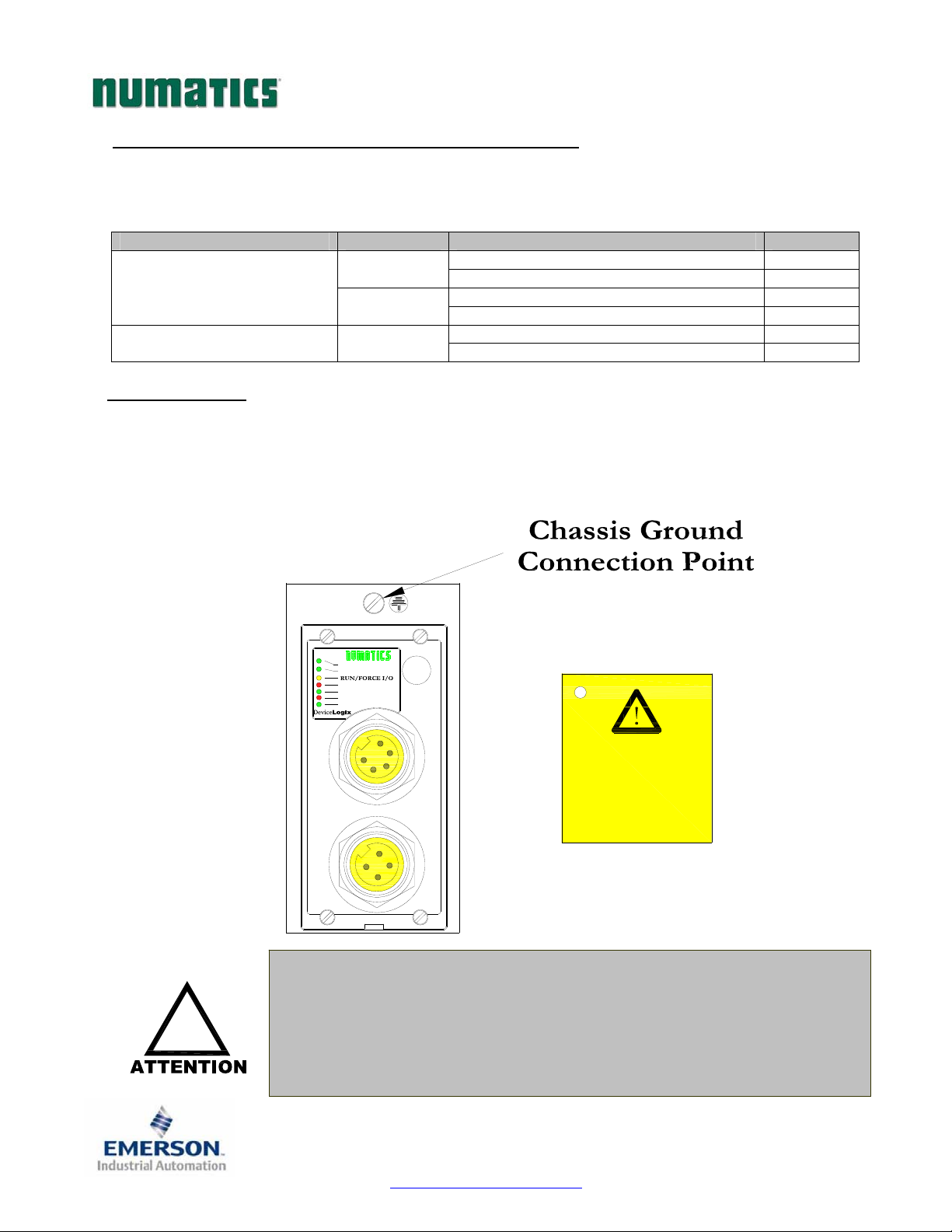
7) Ground Wiring
All Numatics Inc. communication nodes should be grounded during the installation process. These
grounding guidelines can be found in National Electrical code IEC 60204-1 or EN 60204-1. There also is a,
“ATTENTION: CONNECT TO EARTH GROUND FOR PROPER GROUNDING OF UNIT”, label
attached to the chassis ground connection point on the G2-2 series communication node housing. This label
also points out where the grounding guidelines can be found.
!
ON
OFF
ON
NET STATUS
MOD STATUS
FUSE 1
+24V VLV/OUT
FUSE 2
+24V NODE/IN
TM
Proper grounding will alleviate and prevent many intermittent problems
with network communication.
When grounding to a machine frame, please ensure that the machine frame
itself is already properly grounded.
Better grounding can be achieved when larger diameter (lower gauge) wire
is used.
No Fault
Fault No Fault
Fault No Fault 0 Sourcing (PNP)
Fault -
Short Circuit, Over Temp/Over Current 1
Open Load 1
Short Circuit, Over Temp/Over Current 1
ATTENTION:
CONNECT TO EARTH
GROUND FOR PROPER
GROUNDING OF UNIT
Reference National
Electrical code
IEC 60204-1 or EN 60204-1
for grounding guidelines
0
0
3835054 TDG22DLQS3-0 1/07
Subject to change without notice
Page 8
www.numatics.com/fieldbus

y
G2-2 Series DeviceLogix Quick Start Manual
8) Communication Module Connector Pin-Outs
DeviceNet Communication Connector Pin-Out
Pin No. Function Description
1
2
3
4
5
Auxiliary Power Connector Pin-Out
Standard
Pin No.
1 1
2 3 Earth Ground Protective Earth (Case Ground)
3 4 0VDC Common 0VDC Common, for Valves, I/O, and Node Power
4 2
4
COM
5
3
AUX
4
Shield Cable shield
V+
Bus Power, 11-25VDC
V- Bus Power, Common
CAN_H Controller Area Network High, Communication Line
CAN_L Controller Area Network Low, Communication Line
Cenelec
Pin No.
Function Description
+24VDC
(Valves and Outputs)
+24VDC
(Node and Inputs)
Voltage Used to Power Outputs
(Valve Coils and Discrete Outputs)
Voltage Used to Power Discrete Inputs and Node
Electronics
LogixDevice
TM
3
2
MALE
1
COM
LogixDevice
4
1
TM
3
5
MALE
2
COM MALE
2
MALE
1
AUX
2
3
4
MALE
1
AUX
LogixDevice
4
5
1
2
TM
3
2
1
3
MALE
4
Maximum current capacity on the 0VDC common pin of auxiliary power
connector is 8 Amps. The combined draw of the +24VDC Valves & Outputs
and +24VDC Node & Inputs pins cannot exceed 8 Amps, at any given
moment in time.
The auxiliary power Node & Inputs pin supplies power to the node
!
electronics. This pin must be powered at all times for communication node
to be functional.
The Cenelec power connector has a black insert and the standard power
connector has a
3835054 TDG22DLQS3-0 1/07
Subject to change without notice
Page 9
ellow insert.
www.numatics.com/fieldbus
 Loading...