


G2-2 Series AS-i Quick Start Manual
Getting Started
This is a brief document designed to quickly get you started setting up your valve manifold with an integrated
Numatics’ G2-2 AS-i communication node.
1) Initial Unpacking and Inspection
1) Examine exterior of package for signs of damage. Report any damage to shipping carrier.
2) Remove wrapped manifold assembly from box.
a) Remove manifold assembly from anti-static packaging
b) Retain documentation for installation and configuration
3) Examine manifold assembly for any shipping damage such as:
a) Bent pins or connectors
b) Report any damage to shipping carrier immediately
4) Examine manifold assembly for proper ordered configuration. (Valves, I/O, Protocol, etc.)
2) G2-2 Introduction
Below is an example of a 2012 series valve manifold. This fieldbus manifold series is capable of addressing a
total of up to 16 Inputs and 16 Outputs (using 4 separate AS-i addresses. This would include 16 valve outputs
and 16 input connectors, which are located on the top of the AS-i modules. There are 14 AS-i configurations
currently available. Each of the configurations is available in both standard and extended addressing and
contain different configurations of inputs and outputs. Also located on the top of the AS-i modules are two flat
cable connectors: a 2-pin communication connector (yellow cable) and a 2-pin Aux. power connector (black
cable). These connectors are labeled accordingly.
3835051 TDG22ASQS1-4 9/06
Subject to change without notice
Page 1
www.numatics.com/fieldbus

G2-2 Series AS-i Quick Start Manual
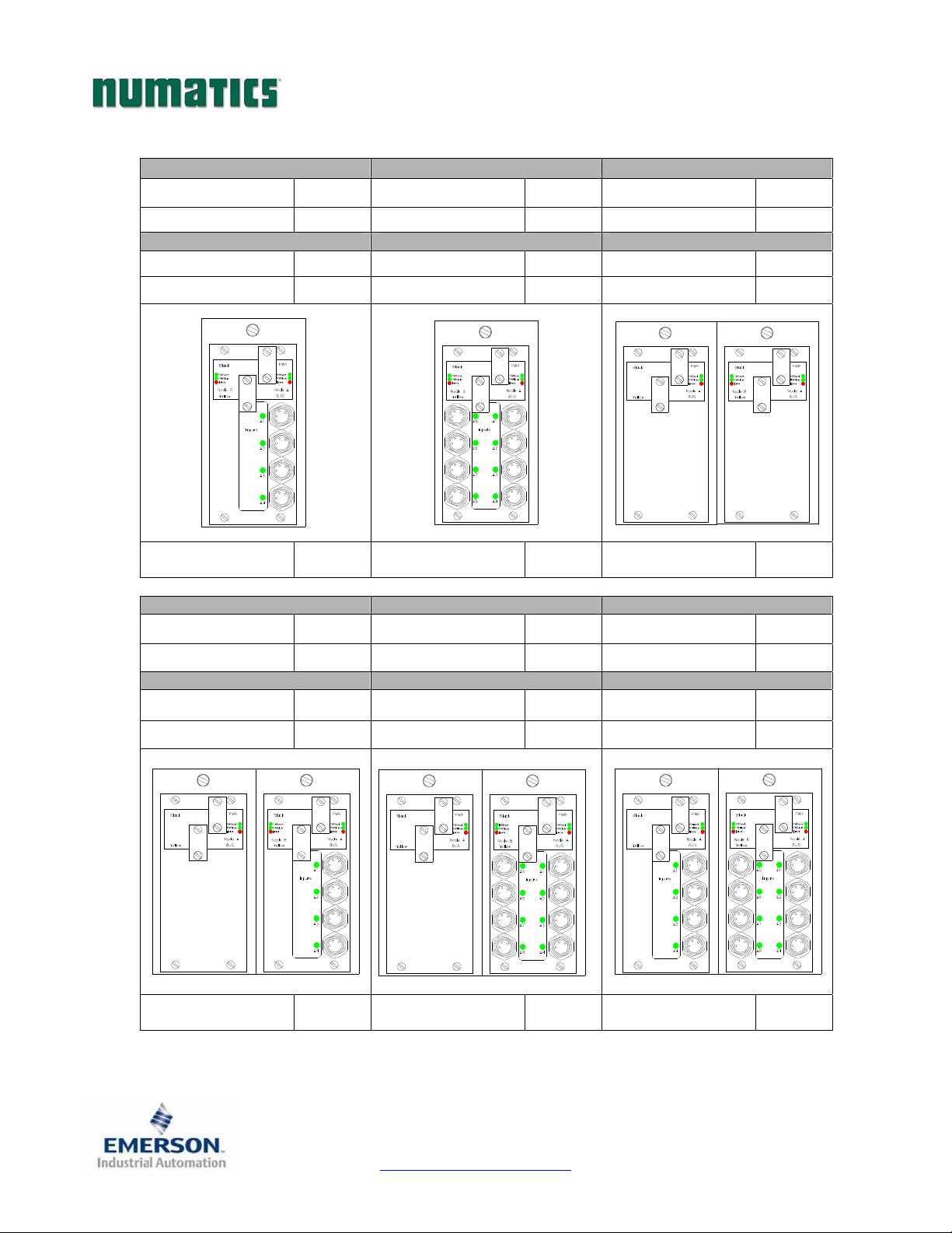
3) AS-i Communication Module Part Numbers
Located below are charts for the different AS-i communication modules and boards currently available. Each
of the modules has either 1,2,3 or 4 AS-i nodes. This allows the user to choose between different numbers of
inputs and coil outputs. Please see below and on the next few pages for the correct I/O values for your
particular application.
AS-i Communication Board Replacement Part Numbers
Connector Type Description Part Number
Standard Addressing Valve Output Board 256-836
Insulation
Displacement
AS-i Complete Communication Module I/O Chart:
Standard Addressing (239-2055) Standard Addressing (239-2058) Standard Addressing (239-2056)
Available Outputs 4 Available Outputs 4 Available Outputs 8
Extended Addressing Valve Output Board 256-907
Cover Assembly with 0 Inputs 205-329
Cover Assembly with 4 Inputs 205-330
Cover Assembly with 8 Inputs 205-331
Available Inputs 0 Available Inputs 4 Available Inputs 0
Extended Addressing (239-2171) Extended Addressing (239-2172) Extended Addressing (239-2166)
Available Outputs 3 Available Outputs 3 Available Outputs 6
Available Inputs 0 Available Inputs 4 Available Inputs 0
2
Number of
addressable nodes
1
Number of
addressable nodes
1
Number of
addressable nodes
3835051 TDG22ASQS1-4 9/06
Subject to change without notice
Page 2
www.numatics.com/fieldbus
G2-2 Series AS-i Quick Start Manual
AS-i Communication Node I/O Chart Continued:
Standard Addressing (239-2059) Standard Addressing (239-2060) Standard Addressing (239-2180)
Available Outputs 8 Available Outputs 8 Available Outputs 12
Available Inputs 4 Available Inputs 8 Available Inputs 0
Extended Addressing (239-2165) Extended Addressing (239-2164) Extended Addressing (239-2176)
Available Outputs 6 Available Outputs 6 Available Outputs 9
Available Inputs 4 Available Inputs 8 Available Inputs 0
2
Number of
addressable nodes
3
Number of
addressable nodes
2
Number of
addressable nodes
Standard Addressing (239-2181) Standard Addressing (239-2231) Standard Addressing (239-2232)
Available Outputs 12 Available Outputs 12 Available Outputs 12
Available Inputs 4 Available Inputs 8 Available Inputs 12
Extended Addressing (239-2175) Extended Addressing (239-2174) Extended Addressing (239-2173)
Available Outputs 9 Available Outputs 9 Available Outputs 9
Available Inputs 4 Available Inputs 8 Available Inputs 12
Number of
addressable nodes
Page 3
3
Number of
addressable nodes
3835051 TDG22ASQS1-4 9/06
Subject to change without notice
www.numatics.com/fieldbus
3
Number of
addressable nodes
3

G2-2 Series AS-i Quick Start Manual
AS-i Communication Node I/O Chart Continued:
Standard Addressing (239-2057) Standard Addressing (239-2177) Standard Addressing (239-2178)
Available Outputs 16 Available Outputs 16 Available Outputs 16
Available Inputs 0 Available Inputs 4 Available Inputs 8
Extended Addressing (239-2169) Extended Addressing (239-2168) Extended Addressing (239-2167)
Available Outputs 12 Available Outputs 12 Available Outputs 12
Available Inputs 0 Available Inputs 4 Available Inputs 8
Number of
addressable nodes
4
Number of
addressable nodes
4
Standard Addressing (239-2179) Standard Addressing (239-2162)
Available Outputs 16 Available Outputs 16
Available Inputs 12 Available Inputs 16
Extended Addressing (239-2170) Extended Addressing (239-2163)
Available Outputs 12 Available Outputs 12
Available Inputs 12 Available Inputs 16
Number of
addressable nodes
4
Number of
addressable nodes
Page 4
4
Number of
addressable nodes
3835051 TDG22ASQS1-4 9/06
Subject to change without notice
www.numatics.com/fieldbus
4
G2-2 Series AS-i Quick Start Manual
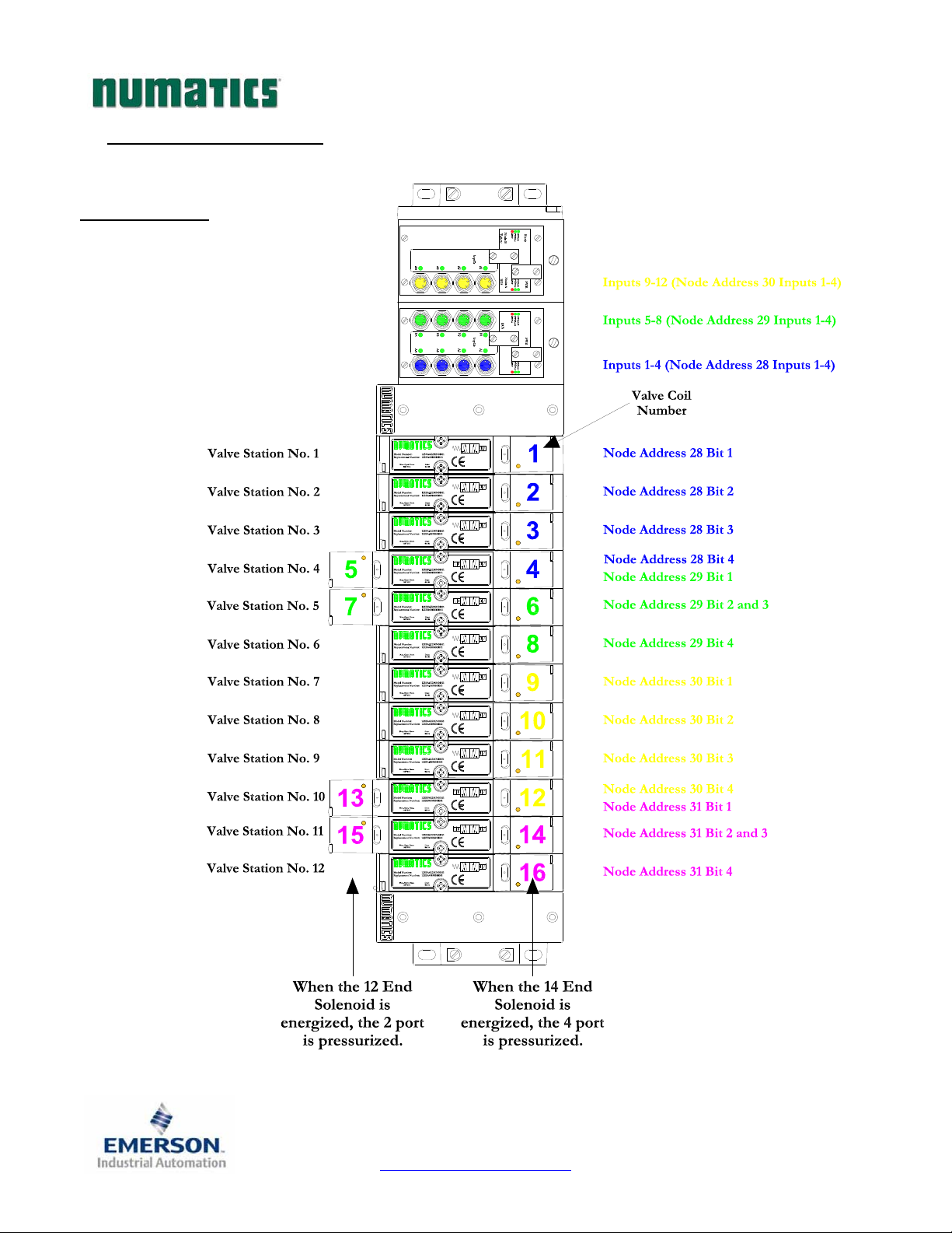
4) I/O Mapping Example
Example:
Assumed Settings
- Single Z-Boards™ are used with single
solenoid valves
- Double Z-Boards™ are used with double
solenoid valves
- Node is configured to use addresses
28, 29, 30 and 31 on an AS-i network
(16 Outputs and 12 Inputs total).
- Node uses standard addressing.
3835051 TDG22ASQS1-4 9/06
Subject to change without notice
Page 5
www.numatics.com/fieldbus
G2-2 Series AS-i Quick Start Manual
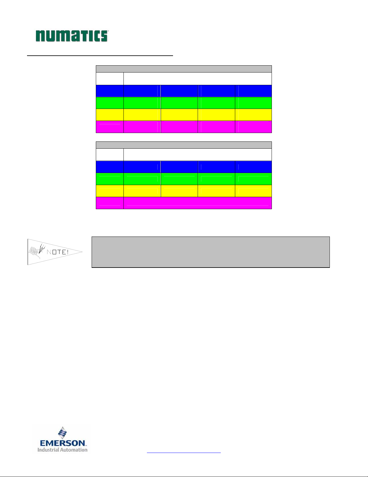
I/O Mapping Table Example Continued
Output Table
Node
Address
28
29
30
31
Node
Address
28 Input No. 1 Input No. 2 Input No. 3 Input No. 4
29 Input No. 1 Input No. 2 Input No. 3 Input No. 4
30 Input No. 1 Input No. 2 Input No. 3 Input No. 4
Valve Coil
No. 1
Valve Coil
No. 5
Valve Coil
No. 9
Valve Coil
No. 13
Output Bit
Valve Coil
No. 2
Valve Coil
No. 6
Valve Coil
No. 10
Valve Coil
No. 14
Input Table
Input Bit
Valve Coil
No. 3
Valve Coil
No. 7
Valve Coil
No. 11
Valve Coil
No. 15
Valve Coil
No. 4
Valve Coil
No. 8
Valve Coil
No. 12
Valve Coil
No. 16
31 Not Available on this Module.
If double z-boards are used to power a single solenoid valve, two outputs
are used instead of just one. This output will be reserved in the output
table even if it is not powering a valve solenoid.
3835051 TDG22ASQS1-4 9/06
Subject to change without notice
Page 6
www.numatics.com/fieldbus
G2-2 Series AS-i Quick Start Manual
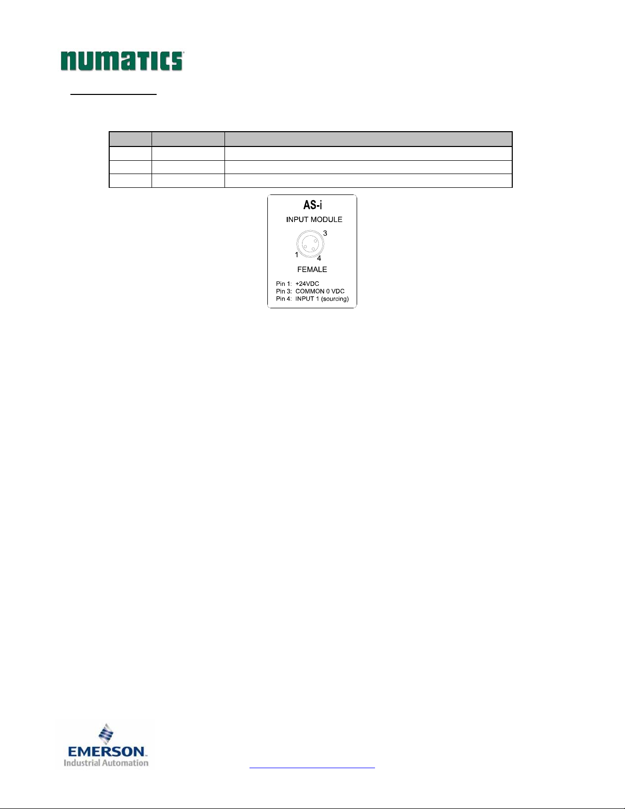
5) Input Pin-Out
AS-i Input 8mm (M8) connector Pin-Out Chart
Pin No. Function Description
1 +24 VDC Input Power
3 0 VDC Input Common
4 Input 1 Input Signal (PNP)
3835051 TDG22ASQS1-4 9/06
Subject to change without notice
Page 7
www.numatics.com/fieldbus
 Loading...