

INBETRIEBNAHMEANWEISUNGEN
Power-Save-Leitungsdosen, Industriestandard Bauform B (11 mm), ISO 4400 / EN 175301-803, Bauform A,
Artikel-Nr. 88100934 / 88100944 (Größe 22), 88100945 (Größe 30)
DE
1. EINFÜHRUNG
Bei der Ansteuerung von Magnetventilen muss ein höherer Anzugsstrom fließen, um das Ventil zu betätigen. Danach ist nur noch
der Haltestrom notwendig, um das Ventil in dieser Stellung zu halten. Die Power-Save-Leitungsdose schaltet nach ca. 140 msec
(Größe 22) bzw. 70 msec (Größe 30) automatisch auf Haltespannung um. Die Haltespannung entspricht 50% der Anzugspannung.
Dadurch wird die Halteleistung auf ¼ der Anzugsleistung reduziert.
Die Absenkung erfolgt besonders leistungsarm durch eine PWMTaktung (Pulsweitenmodulation). Wird das Ventil angesteuert, so
leuchtet eine grüne LED als Funktionsanzeige.
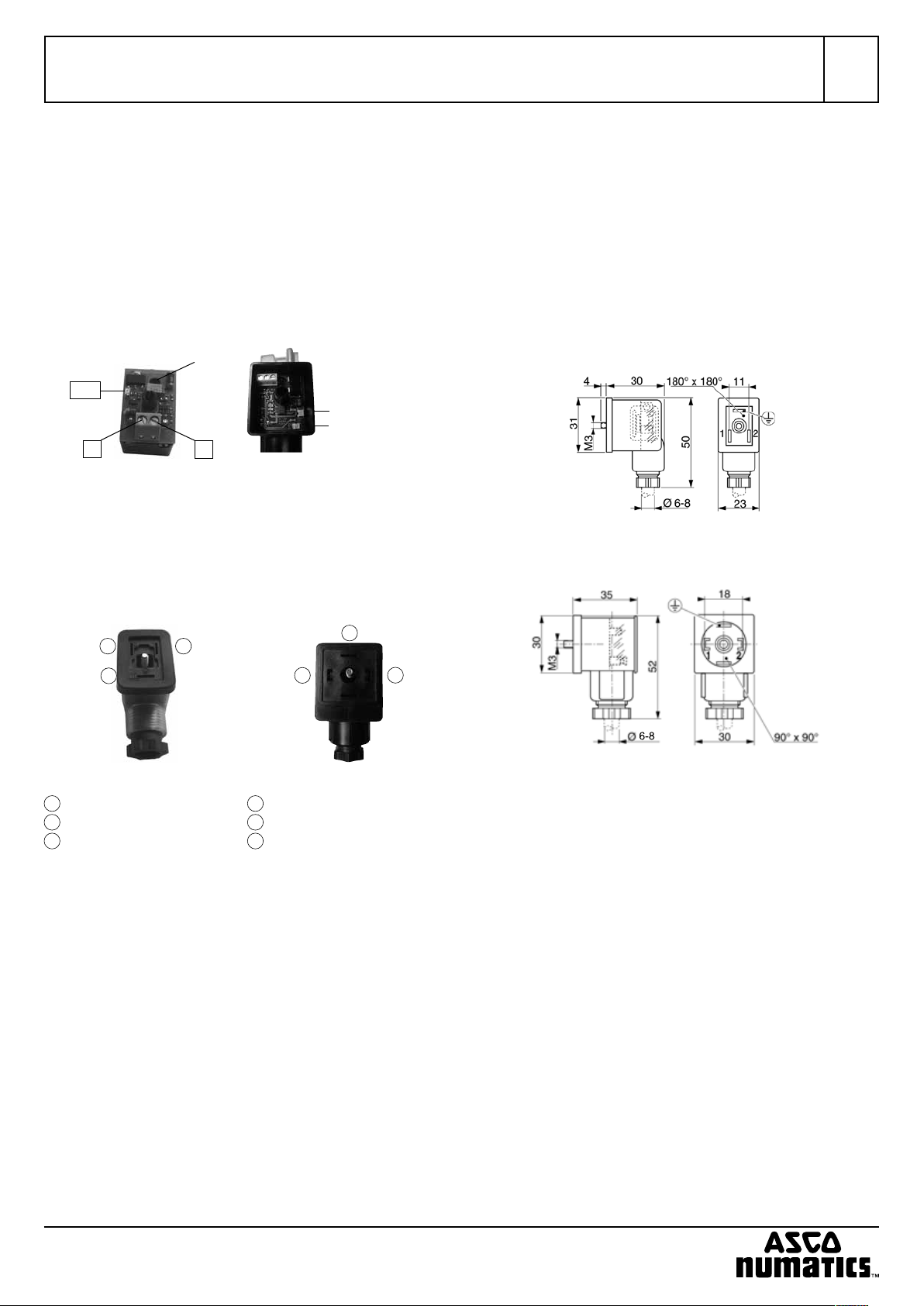
2. ELEKTRISCHE DATEN
j
LED
+
Größe 22 Größe 30
Schraubklemmen: bis 1mm² Kabelquerschnitt
+ = Ansteuerspannung +
(12V/24V)
– = Ansteuerspannung –
(Masse)
j = Erdungsanschluss
(durchgesteckt)
-
+ = Ansteuerspannung +
(10-30V)
- = Ansteuerspannung (Masse)
j = Erdungsanschluss
LED grün
(Magnetventil
angesteuert)
LED rot
(Überstrom
oder Übertemperatur)
Elektrische Daten
Größe 22 Größe 30
Eingangsspannung 12/24 VDC ± 10% 10 bis 30 VDC
Ausgangsspannung 12 VDC ± 10% 6 bis 30 VDC
Leistungsaufnahme max. 12 W max. 30 W
Spannungsabsenkung
PWM-Frequenz
nach 140 ms auf 50% nach 70 ms auf 50%
7 KHz 50 KHz
Betriebsbedingungen
Umgebungstemperatur -10...+50 °C
Lagertemperatur -40...+80 °C
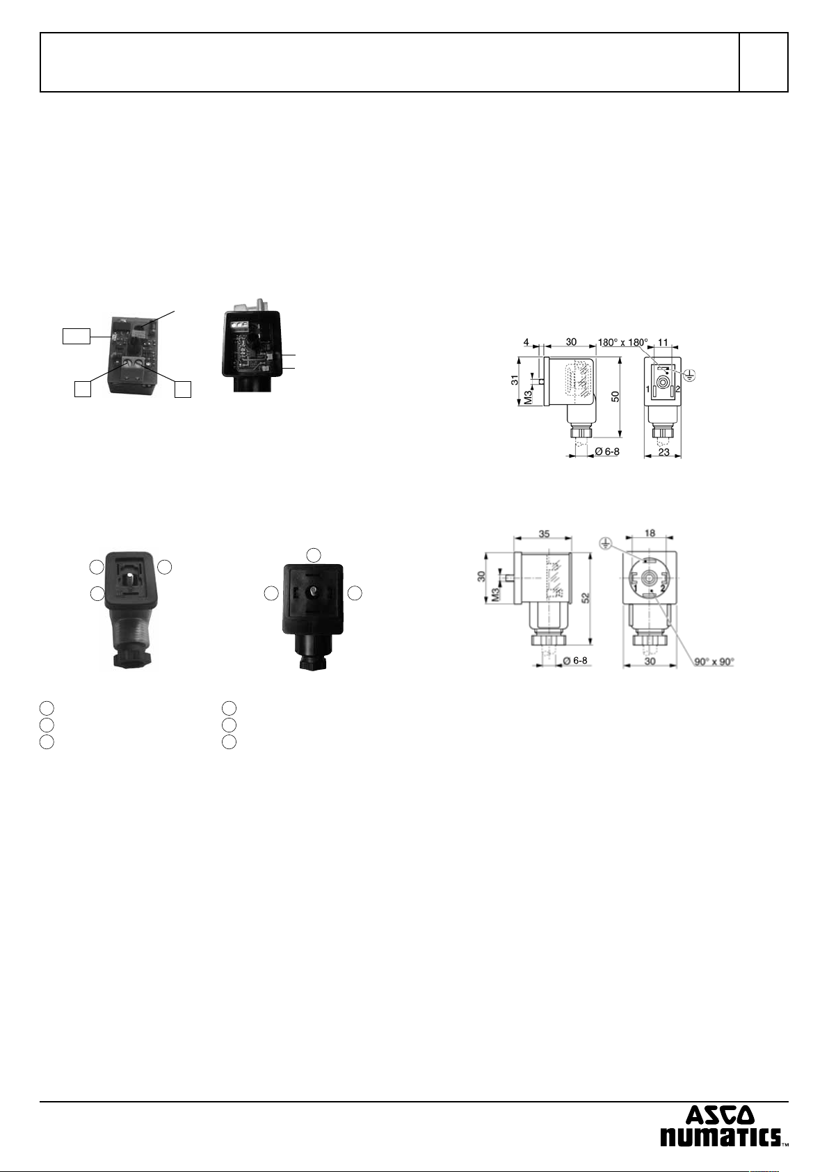
5. ABMESSUNGEN
Größe 22
12
3
2
3
1
Größe 22 Größe 30
1
= Ventilspannung +
2
= Ventilspannung -
3
= Erdungsanschluss
1
= Ventilspannung +
2
= Ventilspannung -
3
= Erdungsanschluss
d Zum Schutz gegen ESD muss in jedem Fall der Erdungs-
anschluss des Ventilsteckers mit der Schutzerde (PE) der Anlage verbunden sein!
3. LED-ANZEIGEN
LED grün = Magnetventil angesteuert (Gr. 22 + Gr. 30)
LED rot = Überstrom oder Übertemperatur (Gr. 30)
4. TECHNISCHE DATEN
Allgemeines
Schutzart IP65
Kabelanschluss Ø 6-8mm
Größe 30
Anmerkungen
Die in diesem Anweisungen enthaltenen Angaben können ohne
vorherige Ankündigung geändert werden. ASCO Numatics übernimmt keinerlei Haftung für technische oder redaktionelle Fehler
oder Ungenauigkeiten oder für versehentlich entstehende Schäden oder Folgeschäden, die durch die Bereitstellung dieser Anweisungen oder aus der Anwendung derselben entstehen.
Herstellererklärung Im Sinne der EU-Maschinenrichtlinie
Hiermit erklären wir, dass das in diesem Installationshandbuch
beschriebene Gerät in der von uns gelieferten Ausführung zum
Einbau oder Zusammenbau mit anderen Maschinen bestimmt ist,
und dass die Inbetriebnahme so lange untersagt ist, bis festgelegt
wurde, dass die Maschine in die das Gerät eingebaut werden soll,
den Bestimmungen der EU-Richtlinie entspricht.
Die Handhabung, Montage und Inbetriebnahme, sowie Einstell- und Justierarbeiten dürfen ausschließlich von autorisiertem
Fachpersonal durchgeführt werden.
Dieses Produkt entspricht der EU-Richtlinie und deren Ergänzungen über die Elektromagnetische Verträglichkeit. Es ist nach CE
zugelassen. Eine Konformitätserklärung steht auf Anfrage zur Verfügung. Eine Herstellererklärung im Sinne der EU-Richtlinie ist auf
Anfrage erhältlich. Geben Sie bitte für die entsprechenden Produkte die Auftragsnummer und Seriennummer an.
IM14194-DE/GB/FR - 2011/R03
Änderungen vorbehalten.
IM14194-1
INSTALLATION INSTRUCTIONS
Power-save connectors, industry standard form B (11 mm), ISO 4400 / EN 175301-803, form A,
catalogue nos. 88100934 / 88100944 (size 22), 88100945 (size 30)
GB
1. INTRODUCTION
Solenoid valve piloting applications require a high inrush current
to activate the valve. Once activated, only the holding current is
necessary to keep the valve in position. The power-save connector
automatically switches to holding voltage after approx 140 msec
(size 2) or 70 msec (size 30). The holding voltage corresponds to
50% of the inrush voltage. The holding power is thereby reduced to
a quarter of the inrush power. This reduction is particularly efficient
due to PWM operation (pulse width modulation). A green function
LED lights up to indicate valve actuation.
2. ELECTRICAL CONNECTION
j
LED
+
Size 22 Size 30
Screw terminals: up to 1mm² cable
+ = Pilot voltage +
(12V/24V)
– = Pilot voltage –
(GND)
j = Earth terminal
(straight through)
-
+ = Pilot voltage +
(10-30V)
- = Pilot voltage (GND)
j = Earth terminal
LED green
(solenoid valve
actuation)
LED red
(overcurrent
or overtemperature
Electrical characteristics
Size 22 Size 30
Input voltage 12/24 VDC ± 10% 10 to 30 VDC
Output voltage 12 VDC ± 10% 6 to 30 VDC
Power rating max. 12 W max. 30 W
Voltage reduction
PWM frequency
50% after approx. 140 ms 50% after approx. 70 ms
7 KHz 50 KHz
Operating characteristics
Ambient temperature -10...+50 °C
Storage temperature -40...+80 °C
5. DIMENSIONS
Size 22
12
3
2
3
1
Größe 22 Größe 30
1
= Valve voltage +
2
= Valve voltage -
3
= Earth terminal
1
= Valve voltage +
2
= Valve voltage -
3
= Earth terminal
d The valve connector’s earth terminal must be connected
to the system’s ground (PE) in order to provide ESD protection!
3. LED INDICATORS
LED green = Solenoid valve actuated (size 22 + size 30)
LED red = Overcurrent or overtemperature (size 30)
4. TECHNICAL CHARACTERISTICS
General
Electrical enclosure protection IP65
Cable connection Ø 6-8mm
Size 30
Notice
The information in these instructions is subject to change without
notice. In no event shall ASCO Numatics be liable for technical or
editorial errors or omissions. Neither is any liability assumed for accidental or consequential damages arising out of or in connection
with the supply or use of the information contained herein.
Manufacturer’s Declaration according to EU Machinery Directive
We herewith declare that the version of the product described in
this installation manual is intended to be incorporated into or assembled with other machinery and that it must not be put into service until the machinery into which it is to be incorporated has been
declared in conformity with the provisions of the EU Directive.
Handling, assembly and putting into service and all adjustments
and fine-tuning must be done by qualified, authorised personnel
only.
This product complies with the EU Directive on electromagnetic
compatibility (as amended). It is CE approved. A declaration of
conformity is available on request. A declaration of conformity within the meaning of the EU Directive is available on request. Please
provide the order number and serial number of the product concerned.
IM14194-2
IM14194-DE/GB/FR - 2011/R03
Availability, design and specifications are subject to change without notice. All rights reserved.
 Loading...