


Mise en service
FR
CARACTERISTIQUES ELECTRIQUES
• Nombre de broches : 3 + terre (broches 12, 14, commun/GND)
• Connexion des fils : bornier à 3 bornes
• Capacité de serrage : 0,14mm
• Mise à la terre : par borne à la partie inférieure
• Tension d’alimentation : 12 à 24 V CC
• Courant maxi de sortie : 150mA par bobine
• Visualisation/protection : 2 Led (14 : jaune, 12 : vert) + diodes de protection
• Matériel certifié CE
Nota : la mise à la terre pour la protection des personnes est à réaliser direc-
tement sur le connecteur via la borne de masse, prévue à cet effet.
SELECTION DU MATERIEL
Connecteur taille 15 - IP20, 3 broches + terre
avec Led de visualisation et protection électrique intégrées
Raccordement par bornier à vis
L
Cavalier de liaison du commun électrique, à l’unité
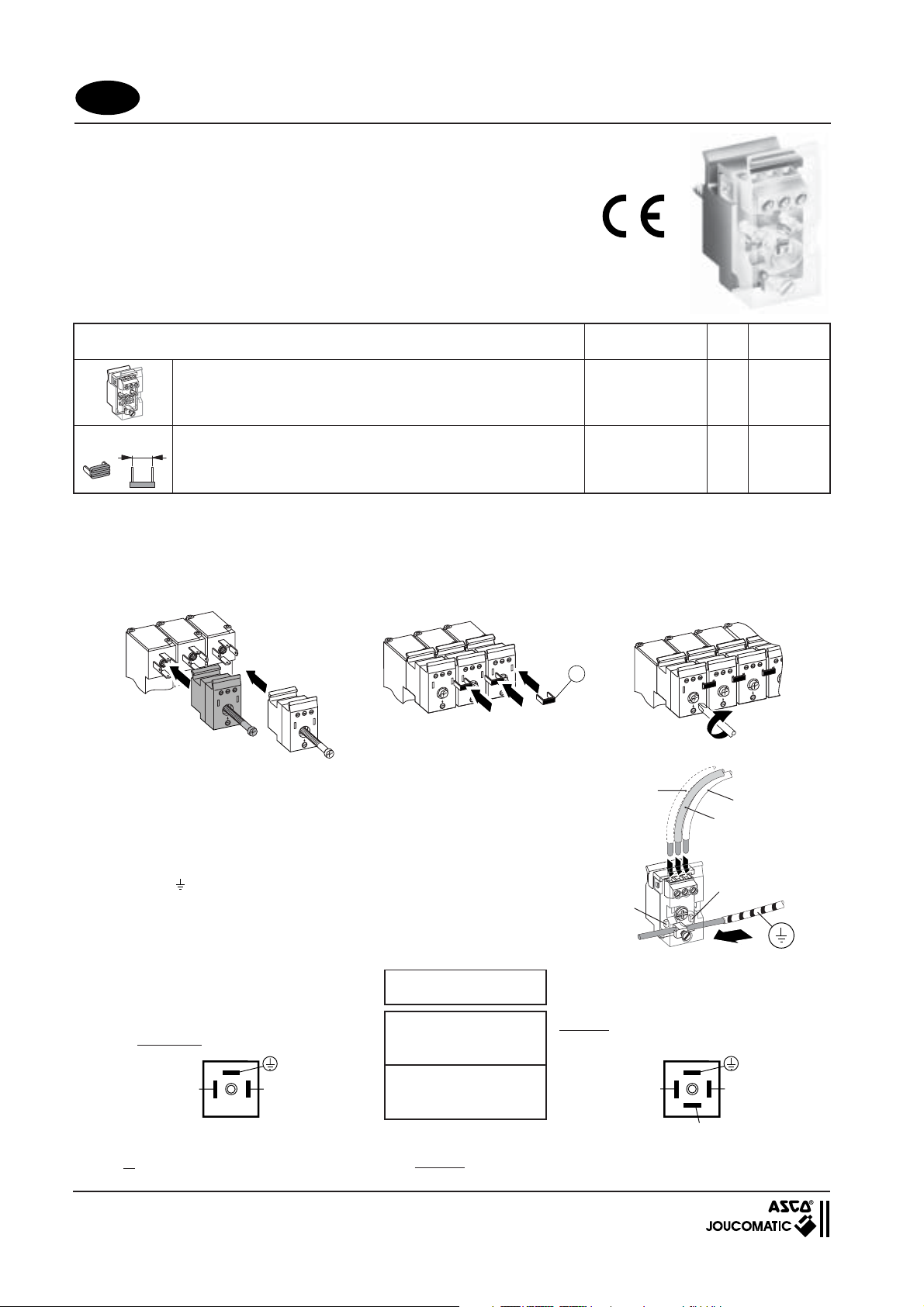
RACCORDEMENT DES CONNECTEURS IP20
Montage
- Embrocher les connecteurs IP20 sur les distributeurs sans les serrer
- Placer les cavaliers (X) qui établissent la liaison du commun électrique sur tous les pilotes de l’ensemble
NOTA - il est possible d’isoler 2 parties du câblage électrique en enlevant 1 cavalier de liaison du commun
- Serrer tous les connecteurs IP20
CONNECTEUR Taille 15 - IP20
2
à 1,5mm
Désignation Code
2
Pour distributeur
série
519 (ØM5)
520 (ØG1/8)
521 (ØG1/4)
578 (MEGA)
519 (ØM5)
520 (ØG1/8)
521 (ØG1/4)
578 (MEGA)
L
(mm)
-
6,9
9,9
13,9
8,9
881 00 411
881 00 412
881 00 414
881 00 415
881 00 413
Câblage
• Dénuder les extrémités des conducteurs
- Raccorder les connecteurs IP20 à bornier à vis par des fils 1,5mm
• 1 fil par bobine (1 pour monostable / 2 pour MEGA bistable)
• 1 seul fil par ensemble pour le raccordement du commun (Z)
• Possibilité de raccorder toutes les masses par un conducteur rigide (
dénudé sur toute la longueur de l’ensemble. Serrer les vis de masse à
la partie basse de chaque connecteur IP20
2
maxi
Signalisation
Le connecteur IP20 est équipé d’une led de visualisation de mise sous
tension de chaque pilote
Repérage broches
(vue côté broches / bobine)
distributeurs 519 - 520 - 521 mono ou bistables (*)
distributeur MEGA monostable
Commun14 Commun14
Connecteurs
non-orientables
Distributeurs 5/2 - 5/3 :
14 = bobine commande
12 = bobine rappel
Distributeur 2 x 3/2 NF :
12B = 14 = commande (B)
12A = 12 = commande (A)
X
Rappel (12)
sur distributeur
MEGA bistable
)
Led (12)
Commande (14)
Commun (Z)
(1 seul fil
par ensemble)
Led (14)
Repérage broches
(vue côté broches / bobine)
distributeur MEGA bistable ou 2x3/2 ou 5/3
(*) Utiliser 2 connecteurs pour les distributeurs 519 - 520 - 521 bistables
12
(383 45 90)
MS-P516-1
Installation
GB
ELECTRICAL CHARACTERISTICS
• Number of pins : 3 + earth (functions 12, 14, common/GND, PE)
• Wire connection : 3 screw terminals
• Wire cross-section : 0.14mm2 to 1.5mm
• Grounding : screw terminal at bottom of connector
• Supply voltage : 12 to 24 V DC
• Max. output current : 150mA per coil
• Visual indication/protection :
• CE mark
Nota : Earthing for personal protection must be effected with the earth terminal
on the connector.
CHOICE OF EQUIPMENT
Connector size 15 - IP20, 3 pins + earth
with integrated LED indicator and electrical protection
Screw terminal connection
L
Jumper for common ground (per unit)
IP20 CONNECTION
Mounting
- Plug the IP20 connectors on spool valves. Do not yet tighten.
- Place the jumpers (X) to establish the common ground for all pilot valves on the unit.
NOTE - You can isolate 2 parts of the electrical wiring by removing 1 common ground jumper
- Tighten all the IP20 connectors.
CONNECTOR Size 15 - IP20
2
2 Leds (14: yellow, 12: green) + protection diodes
Description Code
For spool valve
series
519 (ØM5)
520 (ØG1/8)
521 (ØG1/4)
578 (MEGA)
519 (ØM5)
520 (ØG1/8)
521 (ØG1/4)
578 (MEGA)
L
(mm)
881 00 411
-
881 00 412
6,9
881 00 414
9,9
881 00 415
13,9
881 00 413
8,9
.
Wiring
• Strip the wire ends.
- Connect the wires (max. 1.5 mm² cross-section) to the screw terminals
of the IP20 connectors.
• 1 wire per coil (1 for monostable / 2 for bistable valve).
• 1 single wire per unit to connect the common ground (Z).
• Earth protection for the whole unit can also be effected with a single rigid,
striped wire ( ). Tighten the PE screws at the bottom of the IP20
connectors.
Visual indication
The IP20 connector is equipped with LEDs indicating that the pilots are
supplied with voltage.
Pin assignment
(view from pin/coil side)
monostable or bistable 519-520-521 spool valves (*)
monostable MEGA spool valves
14 Common
Common
GND
Non-rotatable
connectors
5/2 - 5/3 spool valves:
14 = pilot coil
12 = return coil
2 x 3/2 spool valve NC:
12B = 14 = pilot (B)
12A = 12 = pilot (A)
X
Return (12)
on bistable
MEGA
spool valve
Led (12)
PIlot (14)
Common GND (Z)
(1 single wire per
unit)
Led (14)
Pin assignment
(view from pin/coil side)
bistable MEGA spool valve or 2x3/2 or 5/3
14
GND
(*) Use 2 connectors for spool valves 519 - 520 - 521 bistable
P516-1
12
 Loading...