

ASCO European Instruction Manual: Series 541 542 543 Multifunction Spool Valves Manuals & Guides
DISTRIBUTEUR A TIROIR MULTIFONCTION
mise en service
ISO 5599-01 - tailles 1, 2 et 3 - Séries 541, 542 et 543
Commissioning
MULTIFUNCTION SPOOL VALVES
ISO 5599-01 - sizes 1, 2 and 3 - Series 541, 542 and 543
Betriebsanleitung
MULTIFUNKTIONS-WEGEVENTILE
ISO 5599-01 - Grö
β
e 1, 2 - 3 - Baureihen 541, 542 - 543
DESCRIPTION
• Les distributeurs ISO 5599-01 tailles 1, 2 et 3 existent en version prévues pour
atmosphères explosibles sous forme de gaz, vapeurs, brouillard et poussiéreuses selon Directive ATEX 94/9/CE. Leur mise en service et conseils d'utilisation
sont décrits ci-dessous (identiques aux versions standards, sauf spécifi cations
particulières).
SPECIFICATIONS D'UTILISATION
FLUIDE DISTRIBUE : air ou gaz neutre, fi ltré, lubrifi é ou non
RACCORDEMENT : embases
PRESSION D'UTILISATION :
PRESSION DE Cde mini : 1,5 à 3 bar suivant organes de rappel
maxi : 12 bar (10 bar avec pilotes électriques)
DEBIT (Qv à 6 bar) : ISO 1 = 1400 l/min (ANR)
ISO 2 = 2800 l/min (ANR)
ISO 3 = 4200 l/min (ANR)
COEFFICIENT DE DEBIT KV : ISO 1 = 20, ISO 2 = 37,5, ISO 3 = 60
TEMPERATURE AMBIANTE : -10°C à +60°C
PLAN DE POSE : ISO 5599 tailles 1, 2 et 3 - AFNOR NF E49080
MULTIFONCTION
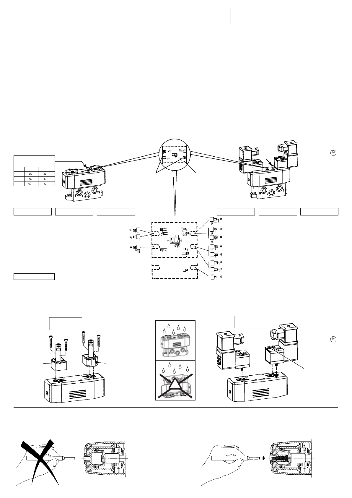
Les distributeurs multifonctions sont équipés de 2 joints sélecteurs de pilotage
situés à la partie supérieure, côté commande et côté rappel. Chaque sélecteur
peut occuper 2 positions pour réaliser l'alimentation interne ou externe des organes
de commande ou de rappel, pneumatique ou électropneumatique. L'alimentation
externe permet d'utiliser les distributeurs sur fl uides de 0 à 12 bar et sur le vide.
Le joint comporte un index avec fl èche qu'il suffi t de positionner dans l'encoche de
la plaque signalétique, face au schéma correspondant au pilotage souhaité (voir
ci-dessous). Toute modifi cation de fonction est aisément réalisable. Les distributeurs sont livrés avec les sélecteurs positionnés pour réaliser les schémas tels que
représentés dans les tableaux de sélection du matériel.
TIGHTENING TORQUE
COUPLES DE SERRAGE
ANZIEHDREHMOMENTE
N.m
ISO 1
8 64
ISO 2
9 72
ISO 3
10 80
0 à 12 bar (avec pilotage en alimentation externe)
3 à 10 bar (avec pilotage en alimentation interne)
Distributeur à commande pneumatique
Spool valve air operated
Wegenventile mit pneum. Vorsteuerung
Inch.Pounds
DESCRIPTION
ISO 5599/01 sizes 1, 2 and 3 spool valves exist in versions intended for use
in potentially explosive atmospheres caused by gases, vapours, mists an/or
dusts (ATEX directive 94/9/EC). Startup and maintenance are to be performed
as detailed below (instructions identical to those for standard versions with the
exception of particular specifi cations).
SPECIFICATION
FLUID : air or neutral gas, fi ltered, lubricated or not
PORTS : subbases
PRESSURE : 0 to 12 bar (with external supply to pliot)
3 to 10 bar (with internal supply to pliot)
PILOT PRESSURE min. : 1,5 to 3 bar depending on return
max. : 12 bar (10 bar with solenoid pilots)
FLOW (Qv at 6 bar) : ISO 1 = 1400 l/min (ANR)
ISO 2 = 2800 l/min (ANR)
ISO 3 = 4200 l/min (ANR)
FLOW COEFFICIENT KV : ISO 1 = 20, ISO 2 = 37,5, ISO 3 = 60
TEMPERATURE : -10°C, +60°C
BASES : ISO 5599 sizes 1, 2 and 3
MULTIFUNCTION
Multi-function valves are fi tted with 2 pilot selector seals on the top face, on both
pilot and return sides. These selector seals can be fi tted in 2 positions to give internal
supply to the pilot or return and external supply to the pilot or return. This applies to
pneumatic and electro-pneumatic versions. External supply allows the valves to be
used with supply pressures between 0 and 12 bar and under vacuum pressure.
The seal has a tag with arrow which can be fi tted into a notch in the label. Thenotch
is opposite the diagram corresponding to the pilot function required (see below). Modifi cations of the function are very simple. The valves are delivered with the selectors
in the position indicated and appropriate to the valve code selecting.
Index avec fl èche
Tag with arrow
Index mit Pfeil
Plaque signalétique
Product label
Producktetikett
BESCHREIBUNG
Die Wegenventile ISO 5599/01 Gröβe 1, 2 - 3 stehen in verschiedenen Versionen
für den Einsatz in explosionsfähigen Atmosphären, die durch Gase, Dämpfe,
Nebel oder Staub verursacht werden (ATEX-Richtlinie 94/9/EG), zur Verfügung.
Die Inbetriebnahme und Wartung hat nach den nachstehenden Anweisungen zu
erfolgen (identisch zu denen für die Standardversionen, besonderer Spezifi kationen
ausgenommen).
ALLGEMEINES
MEDIUM :
ANSCHLUSS : Grundplatten
BETRIEBSDRUCK : 0 bis 12 bar (bei externer Vorsteuerung)
3 bis 10 bar (bei interner Vorsteuerung)
BETÄTIGUNGSDRUCK min. : 1,5 bis 3 bar, je nach Rückstellung
max. : 12 bar (10 bar mit elektr. pilot)
DURCHFLUSS (Qv bis 6 bar) : ISO 1 = 1400 l/min (ANR)
ISO 2 = 2800 l/min (ANR)
ISO 3 = 4200 l/min (ANR)
DURCHFLUSSWERT KV
UMGEBUNGSTEMPERATUR : -10°C, +60°C
AUFFLANSCHBILD : ISO 5599, Größen 1, 2 und 3
MULTIFUNKTION
Die Multifunktionsventile sind oben sowohl auf der Ansteuerungs- als auch auf
der Rückstellseite mit zwei Selektionsdichtungen ausgestattet. Diese Selektionsdichttungen Können in zwei Stellungen gebracht werden, damit die jeweilige Einspeisung für die Ansteuerung und für die Rückstellung intern oder extern erfolgen
kann. Dies gilt sowohl für die pneumatische als auch für die elektropneumatische
Ausführung. Bei externer Einspeisung beträgt der Betriebsdruck 0 bis 12 bar, auch
bei Vakuum. Zu diesem Zweck muß lediglich der Pfeil auf der Selektionsdichtung
in die Aussparung mit dem Diagramm der gewünschten Funktion plaziert werden
(siehe unten). Die Funktionen können beliebig geändert werden. Die Dichtungen
befi nden sich bei der Auslieferung der Ventile in der Stellung, die der bestellten
Funktionsart entspricht.
Luft, oderneutrale Gase, gefi ltert geölt, oder ungedeölt
(l/min) : ISO 1 = 20, ISO 2 = 37,5, ISO 3 = 60
Pilotes version
standard ou ATEX
Pilots : ATEX or
standard version
Pilotventile ATEX-
oder Standard-Version
Distributeur à commande
électropneumatique
Spool valve solenoid operated
Wegenventile mit
elektro-pneum. Vorsteuerung
ATEX
Organes de commande
(côté 14)
Electropneumatique
alimentation externe
Pneumatique
alimentation externe
Electropneumatique
alimentation interne
Pilot operators
(side 14)
Solenoid-air
external supply
Air operated
external supply
Solenoid-air
internal supply
Ansteueralement
(Seite 14)
Elektropneumatisch
Fremdmedium
Pneumatisch
Fremdmedium
Elektropneumatisch
Eigenmedium
P. MAX = 10/12 bar
MONTAGE DU (DES) ELECTROVANNE(S) - PILOTE(S)
- L’assemblage du (des) électrovannes(s) pilotes(s) ATEX sur le distributeur ATEX
ne crée pas de dangers supplémentaires d’infl ammation et ne modifi e en rien la
classifi cation Atex du distributeur.
Oter le protecteur en plastique des joints situés à la partie supérieure du distributeur.
-
- S'assurer de la position correcte du joint fi xe et du joint sélecteur.
- Respecter la position de montage de l'électrovanne par rapport au corps du
distributeur (voir ci-dessous).
Côté commande (14)
Side pilot (14)
Ansteuerseite (14)
Commande manuelle
Manual override
Handhifsbetätigung
EV série 189
EV serie 189
MV - serie 189
Côté rappel (12)
Side return (12)
Rückstellseite (12)
Commande manuelle
Manual override
Handhifsbetätigung
Organes de rappel
Différentiel
alimentation interne
Electrodifférentiel
alimentation interne
Electropneumatique
alimentation interne
Electropneumatique
alimentation externe
Electrodifférentiel
alimentation externe
Pneumatique
alimentation externe
Différentiel
alimentation externe
Ressort
MOUNTING OF SOLENOID PILOT VALVE (S)
- The assembly of an ATEX-approved pilot valve on an ATEX-approved directional
valve does not present any additional hazard of ignition and does not modify in
any way the ATEX classifi cation of the directional valve.
- Remove the plastic protector from the seals on the top of the valve.
Check the correct position of the seal and the correct position of the selector seal.
-
-
Ensure that the solenoid valve is positioned correctly on the top of the valve (see below).
☺
(côté 12)
MONTAGE DER PILOTVENTILE
- Die Montage eines Pilotventils mit ATEX-Zulassung auf einem Wegeventil mit
ATEX-Zulassung stellt keine zusätzliche Explosionsgefahr dar und bedeutet
keinerlei Änderung der ATEX-Klassifi zierung.
- Die Plastikschutzkappe über den Dichtungen auf dem Wegeventil abnehmen
- Stellung der Selektionsdichtungen überprüfen.
- Die Positionierung des Pilotventiles auf dem Wegeventil beachten (siehe unten).
EV série 190 - 192
EV serie 190 - 192
MV - serie 190 - 192
Return operators
(side 12)
Differential
internal supply
Solenoid- differential
internal supply
Solenoid- air
internal supply
Solenoid- air
external supply
Solenoid- differential
external supply
Air
external supply
Differential
external supply
Spring
Rückstellelement
(Seite 12)
Differential
Eigenmedium
Elektrodifferential
Eigenmedium
Elektropneumatisch
Eigenmedium
Elektropneumatisch
Fremdmedium
Elektrodifferential
Fremdmedium
Pneumatisch
Fremdmedium
Differential
Fremdmedium
Feder
Pilotes version
standard ou ATEX
Pilots : ATEX or
standard version
Pilotventile ATEX-
oder Standard-Version
Commande manuelle
Manual override
Handhifsbetätigung
ATEX
SANS TESTEURS MANUELS DE POSITION
WITHOUT MANUAL TESTER INDICATING THE SPOOL POSITION
OHNE KOMBINIERTE HANDHILFSBETÄTIGUNG / POSITIONSANZEIGE
Le perçage du boitier interne de pilotage entraine la détérioration du distributeur.
Transpiercing the body of the internal pilot will damage the valve.
Das Durchstoßen des Gehäuses der internen Vorsteuerung führt zu einer Beschädigung des Ventils.
!
AVEC TESTEURS MANUELS DE POSITION
WITH MANUAL TESTERS INDICATING THE SPOOL POSITION
MIT KOMBINIERTER HANDHILFSBETÄTIGUNG / POSITIONSANZEIGE
Les distributeurs équipés de testeurs manuels permettent le contrôle de position du tiroir ou la commande
manuelle de déplacement de celui-ci.
The manual testers on the spool valves serve to check and change the spool position.
Mit der kombinierten Handhilfsbetätigung / Positionsanzeige kann die Schieberposition überprüft und verändert werden.
(383 48 05)
MS - P570-3f

DISTRIBUTORI A CASSETTO MULTIFUNZIONALE
Messa in servizio
ISO 5599-01 Taglie 1, 2 e 3 - Serie 541, 542 e 543
DISTRIBUIDORES DE CORREDERA MULTIFUNCIONAL
Puesta en servicio
ISO 5599-01 Tallas 1, 2 y 3 - Series 541, 542 y 543
In bedrijtstelling
MULTIFUNKTIE SCHUIFVENTIEL
ISO 5599-01 Maat 1, 2 en 3 - Serie 541, 542 en 543
DESCRIZIONE
I distributori sono disponibili nelle versioni per atmosfere pericolose sotto forma
di gas, vapori, nebbie e polveri (direttiva ATEX 94/9/CE) : l'installazione e la
manutenzione sono basate sulle indicazioni sotto riportate (identici alle versioni
standards, salvo specifi che particolari).
GENERALITÀ
FLUIDO CONTROLLATO : aria o gas neutri, fi ltrati, lubrifi cati o no
RACCORDI : basi
PRESSIONE DI UTILIZZAZIONE
3 - 10 bar (con pilota e alimentazione interna)
PRESSIONE DI COMANDO min.
max. : 12 bar (10 bar con comando elettr ico)
PO R TATA (Qv a 6 bar) : ISO 1 = 1400 l/min (ANR)
ISO 2 = 2800 l/min (ANR)
ISO 3 = 4200 l/min (ANR)
COEFFICIENTE DI PORTATA KV
TEMPERATURA AMBIENTE : -10°C, +60°C
PIANO DI POSA : ISO 5599 Taglie 1, 2 e 3
MULTIFUNZIONALITÀ
l distributori multifunzionali sono dotati di 2 giunti selettori di pilotaggio montati
sulla parte superiore, dal lato comando e dal lato ritorno. Ogni selettore puo essere
montato in 2 posizioni per realizzare l'alimentazione interna o esterna degli organi
di comando o di ritorno, pneumatico o elettropneumatico. Il pilotaggio esterno
consente di utilizzare i distributori con fl uidi da 0 a 12 bar come pure sul vuoto. Il
giunto selettore possiede un indice con una freccia che permette di segnalare sulla
targhetta il corrispondente schema di pilotaggio realizzato (vedi sotto). Ogni modifi ca
è facilmente realizzabile. I distributori sono forniti con i giunti selettori pozionati in
modo da realizzare gli schemi riportati sulle tabelle della scelta dei materiali.
PARES DE APRIETE
COPPIE DI SERRAGGIO
AANDRAAIMOMENTEN
N.m
ISO 1
8 64
ISO 2
9 72
ISO 3
10 80
Organi di comando
(lato 14)
Elettropneumatico
alimentazione esterna
Pneumatico
alimentazione esterna
Elettropneumatico
alimentazione interna
: 0 - 12 bar (con pilota e alimentazione esterna)
: 1,5 - 3 bar secondo il tipo di ritorno
: ISO 1 = 20, ISO 2 = 37,5, ISO 3 = 60
Distributore a comando pneumatico
Distribuidor de mando neumático
Elektropneumatisch bediend ventiel
Inch.Pounds
Organos de mando
(lado 14)
Electroneumático
alimentación externa
Neumático
alimentación externa
Electroneumático
alimentación interna
Stuurorganen
(kant 14)
Elektro-pneumatisch
externe voeding
Pneumatisch
externe voeding
Elektro-pneumatisch
interne voeding
P. MAX = 10/12 bar
DESCRIPCIÓN
Los distribuidores existen en versiones previstas para ambientes explosivos bajo
forma de gas, vapores, niebla y polvo (directiva ATEX 94/9/CE) : su puesta en
marcha y mantenimiento se hacen según las indicaciones siguientes (idénticas
a las versiones standards, salvo especifi caciones particulares).
ESPECIFICACIONES
FLUIDO : aire o gas neutro, fi ltrado, lubricado o NO
RACORDAJE : base
PRESION DE UTILIZACION : 0 a 12 bar (alimentación externa)
3 a 10 bar (alimentación interna)
PRESION DE MANDO mini : 1,5 a 3 bar (según retorno)
maxi : 12 bar (10 bar con pilotos eléctricos)
CAUDAL (Qv a 6 bar) : ISO 1 = 1400 l/min (ANR)
ISO 2 = 2800 l/min (ANR)
ISO 3 = 4200 l/min (ANR)
COEFICIENTE DE CAUDAL KV
TEMPERATURA AMBIENTE : -10°C, +60°C
PLANO DE ACOPLAMIENTO : ISO 5599 Tallas 1, 2 y 3
MULTIFUNCION
Los distribuidores multifuncionales estan equipados con 2 juntas selectoras de
pilotaje situadas en la parte superior, lado mando y retorno. Cada junta selectora
puede ocupar 2 posiciones para realizar alimentación interna o externa de los
órganos de mando o de retorno, neumático o electroneumático. La alimentación
externa permite utilizar los distribuidores con fl uidos de 0 a 12 bar y vacio. La junta
lleva consigo un indicator con fl echa que se posicionará en frente del esquema
correspondiente al pilotaje deseado (verabajo). Cualquier modifi cación de la función
se realiza fácilmente. Los distribuidores se suministran con las juntas selectoras
posicionadas para realizar los esquemas representados en el cuadro de selección
de material.
Indice con freccia
Indicator con fl echa
Aanduiding met pijl
: ISO 1 = 20, ISO 2 = 37,5, ISO 3 = 60
Targhetta segnaletica
Placa caracteristicas
Signalisatieplaat
Organi di ritorno
Differenziale
alimentazione interna
Elettrodifferenziale
alimentazione interna
Elettropneumatico
alimentazione interna
Elettropneumatico
alimentazione esterna
Elettrodifferenziale
alimentazione esterna
Pneumatico
alimentazione esterna
Differenziale
alimentazione esterna
Molla
BESCHRIJVING
De schuifventiel bestaat uit versies, geschikt voor gebruik in explosiegevaar-
lijke omgevingen bestaande uit gassen, dampen, nevels of stoffen (ATEX
richtlijn 94/9/EC): de installatie en het onderhoud dienen te geschieden volgens
de aanwijzingen hieronder (identiek aan de standaard versies, m.u.v. bijzondere
specifi caties)
ALGEMENE BESCHRIJVING
MEDIUM : lucht of neutraal gas, al of niet gesmeerd
AANSLUITING : met basisplaat
WERKDRUK : 0 tot 12 bar (sturing met externe voeding)
3 tot 10 bar (sturing met interne voeding)
STUURDRUK :
: maximum 12 bar (10 bar met elektro-piloot)
DEBIET (Qv bij 6 bar) : ISO 1 = 1400 l/min (ANR)
ISO 2 = 2800 l/min (ANR)
ISO 3 = 4200 l/min (ANR)
DOORSTROOMFAKTOR KV (l/min)
OMGEVINGSTEMPERATUUR : -10°C, +60°C
GESCHIKT VOOR BASISPLAAT
MULTIFUNKTIE
De multifunktieverdelers zijn uitgerust met 2 sturingseleetordichtingen die zich in
het bovenvlak bevinden, kant sturing en kant retour. ledere selector kan 2 standen
innemen voor het realiseren van de interne of externe voeding van de stuurorganen
of de retour, pneumatisch of elektropneumatisch. De externe voeding laat toe van
de schuifverdelers te gebruiken media van 0 tot 12 bar en op vacûm. De dichting
heeft een aanduiding met pijl die men dient te plaatsen rechtover het gewenste
stuurschema (zie hieronder). ledere funktiewijziging is vlot te realiseren. De verdelers
zijn geleverd met de selectors, gepositioneerd voor de realisatie van de schema o
zoals voorgesteld in de materiaalkeuze tabellen.
(lato 12)
minimum 1,5 tot 3 bar, naar gelang retour orgaan
: ISO 1 = 20, ISO 2 = 37,5, ISO 3 = 60
: ISO 5599, mast 1, 2 en 3
Pilota (versioni
standard o ATEX)
Pilotos : (versiones
standards o ATEX)
Stuurventielen
(standaard of ATEX versies)
Distributori a comando
-elettropneumatico
Distribuidor de mando electroneumático
Elektro-pneumatisch bediend
ventiel
Organos de retorno
(lado 12)
Diferencial
alimentación interna
Electrodiferencial
alimentación interna
Electroneumático
alimentación interna
Electroneumático
alimentación externa
Electrodiferencial
alimentación externa
Neumático
alimentación externa
Diferencial
alimentación externa
Resorte
Retour organen
Differentie
interne voeding
Elektro-differentie
interne voeding
Elektro-pneumatisch
interne voeding
Elektro-pneumatisch
externe voeding
Elektro-differentie
externe voeding
Pneumatisch
externe voeding
Differentie
externe voeding
Veer
(kant 12)
ATEX
MONTAGGIO DELLE ELETTROVALVOLE PILOTA
- L’assemblaggio della(e) elettrovalvola(e) pilota ATEX su distributore ATEX non
crea ulteriori pericoli d’infi ammabilità e non modica la classifi cazione Atex del
distributore.
- Togliere la pianistra di protezione in plastica montata sulla parte superiore del
distributore.
- Assicurarsi che la posizione del giunto fi sso e del giunto selettore siano quelle
desiderate.
- Rispettare la posizione di montaggio dell'elettrovalvola sul corpo del distributore.
(vedi sotto)
Lato comando(14)
Lado mando (14)
Kant sturing (14)
Comando manuale
Mando manual
Handbediening
SENZA COMANDI MANUALI DIRETTI SUL CASSETTO
SIN CONTROLADORES MANUALES DE POSICION
ZONDER MANUELE STANDTESTER VAN DE SCHUIF
Lo spostamento del cassetto interno tramite i fori laterali comporta il danneggiamento del distributore.
Taladrar la casa interna del pilotaje provoca el deterioro del distribuidor.
Het doorboren van de interne stuurbehuizing leidt tot beschadiging van het shuifventiel.
EV serie 189
EV serie 189
MV - serie 189
Lato ritorno (12)
Lado retorno (12)
Kant retour (12)
MONTAJE DE (DE LAS) ELECTROVALVULA ( S) - PILOTO (S)
- El montaje de la (las) electroválvula(s) piloto(s) ATEX en el distribuidor ATEX no
crea peligros suplementarios de infl amación y no modifi ca en nada la clasifi cación
Atex del distribuidor.
- Sacar el protector de plástico de las juntas situadas en la parte superior del
distribuidor.
- Asegurarse de la correcta posición de la junta fi ja y de la junta selectora.
- Respetar la positción de montaje de la electroválvula con relación. al cuerpo del
distribuidor (ver abajo).
Comando manuale
Mando manual
Handbediening
☺
MONTAGE VAN HET (DE) STUURVENTIEL (EN)
- De montage van de ATEX magneetkop(pen)op het ATEX schuifventiel creëert
geen bijkomend gevaar voor ontbranding en wijzigt in geen enkel opzicht de ATEX
classifi catie van het schuifventiel.
- Plastieke beschermkap van de dichtingen wegnemen op het bovenvlak van de
verdeler
zich verzekeren van de juiste positie van de vaste dichting en de selector dichting.
-
- De montagepositie van het elektroventiel ten aanzien van het lichaam van de
verdeler eerbiedigen (zie hieronder).
EV serie 190 - 192
EV serie 190 - 192
MV - serie 190 - 192
Pilota (versioni
standard o ATEX)
Pilotos : (versiones
standards o ATEX)
Stuurventielen
(standaard of ATEX versies)
Comando manuale
Mando manual
Handbediening
ATEX
!
CON COMANDI MANUALI DIRETTI SUL CASSETTO
CON CONTROLADORES MANUALES DE POSICION
MET MANUELE STANDTESTER VAN DE SCHUIF
l distributori sono dotatidi comandi manuali che permettono di controllare la posizione
del cassetto interno come pure di effettuarme il comando manuale diretto.
Los distribuidores equipados de controladores manuales permiten el control de posicion de la corredera o el
mando manual por desplazamiento de esta.
De shuifventielen, welke uitgevoerd zijn met manuele standtester, bieden de mogelijkheid tot hand bediening
en positiebepaling van de shuif.
 Loading...