

ASCO European Instruction Manual: Series 538 539 Solenoid Joinable Subbases Manuals & Guides

mise en service - installation - Inbetriebnahme
GB
DE
;
;
;;;;;;;;
;
;
;;;;;;;;
;
FR
EMBASES JUXTAPOSABLES VDMA 24 563 - ISO 02 (distributeurs 538)
JOINABLE SUBBASE VDMA 24 563 - ISO 02 (spool valves 538)
ANREIHGRUNDPLATTEN VDMA 24 563 - ISO 02 (Wegeschieber 538)
A
315
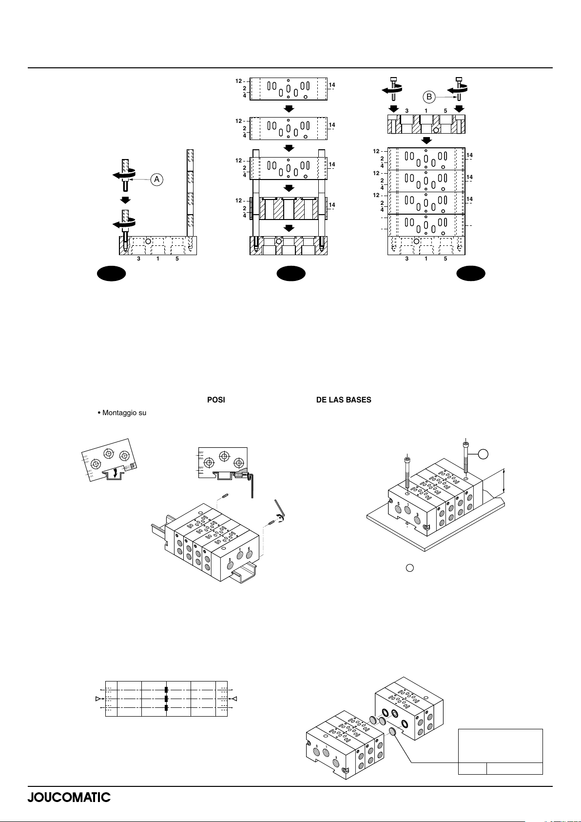
ASSEMBLAGE DES EMBASES
- Visser les colonnettes (A) sur l'embout comprenant
2 trous taraudés
- Placer autant de colonnettes que d'embases à
assembler
- S'assurer de la mise en place correcte des joints
d'étanchéité sur les embases et embouts
- Introduire une par une les embases dans le sens
indiqué ci-dessus (se référer aux repères d'orifi ces
pour un montage correct)
- Placer le second embout avec trous lisses
- Serrer l'ensemble à l'aide des 2 vis CHC (B)
POSSIBILITES DE FIXATION DES EMBASES
• Montage sur profi lé symétrique EN 50022
• Mounting on EN 50022 symmetrical rail
• Montage auf Profi lschiene nach EN 50022
12
2
4
12
2
4
12
2
4
12
2
;;;;;;
4
;;;;;;
315
14
14
12
14
12
12
14
12
ASSEMBLY OF SUBBASES
- Screw the posts (A) to the end fi tting with 2
tappings
- Install as many posts as there are subbases to be
assembled
- Check that the seals are properly positioned in the
sub-bases and end fi ttings
- One by one, slide the subbases into place in the
direction indicated (the port markings show the
correct orientation)
- Fit the second end fi tting with unthreaded holes
- Fix the components together with two caps
screws (B)
DIFFERENT SUBBASE MOUNTING POSSIBILITIES
B
315
;;;;;;;
2
4
2
4
2
4
2
4
315
14
14
14
14
MONTAGE DER ENDPLATTEN
-
Schrauben Sie die Verbindungsbolzen (A) in die mit
2 Gewindebohrungen versehene Endplatte ein.
- Schrauben Sie so viele Verbindungsbolzen auf, wie
Anschlußplatten zu montieren sind.
Vergewissern Sie sich, daß die Dichtungen an den An-
schlußplatten und Endplatten richtig eingesetzt sind.
- Fügen Sie eine Anschlußplatte nach der anderen in
der oben angegebenen Weise an (achten Sie dabei
auf die richtige Lage der Anschlüsse).
- Befestigen Sie die zweite Endplatte mit den glatten
Bohrungen.
Befestigen Sie die Einheit mit 2 CHC-Schrauben (B).
-
ANSCHLUSSMÖGLICHKEITEN
• Montage sur bâti ou chassis
• Installation on frame or baseplate
• Montage auf Maschinenkonsole oder Rahmen
1
3
5
• Nota : la fi xation est réalisée
par 2 vis pointeau situées sur
les embouts
• Note: the unit is secured
with two set screws at the
end fi ttings
• Anmerkung: Die Einheit wird
mit 2 Arretierschrauben an den
Endplatten befestigt.
NOTA - 5 distributeurs peuvent fonctionner simul-
tanément, au maximum, sans perturbation pneumatique; Au delà il est nécessaire d'alimenter en
pression les deux cotés de l'embase et d'ôter les
bouchons (3) et (5)
LOT D'OBTURATEURS
Principe de montage du lot d'obturateurs permettant
l'alimentation des embases juxtaposables par 2
pressions différentes
5
1
P1
3
• Remarque : lors de l'assemblage des embases ne pas omettre
de positionner les obturateurs à l'endroit opportun
• Note: When assembling the bases, make sure to fi t the blanking
disks at the correct place
• Anmerkung: Bei der Montage der Anschlußplatten ist auf die
richtige Lage der Verschlußstopfen zu achten.
2
4
1
3
5
NOTE: The maximum number of control valves which
can operate simultaneously without pneumatic
disturbance is 5. If there are more, it is necessary to
supply pressure from both sides of the end fi ttings
and to remove plugs (3) and (5).
SET OF BLANKING DISKS
A set of blanking disks is fi tted as follows to enable supply of joinable sub-bases with two different
pressures
5
1
P2
3
C
H
• Fixation • Mounting • Befestigung
ISO02= c : 2 CHC ØM5 H = 40 mm
ANMERKUNG - Es können
gleichzeitig maximal 5
Wegeschieber ohne Störung in der Pneumatik betrieben
werden. Bei mehr als 5 Ventilen muß die Druckluft über
beide Seiten der Anschlußplatten eingespeist und die
beiden Stopfen (3) und (5) entfernt werden.
VERSCHLUSSSTOPFEN
Anordnung der Verschlußstopfen für die Beauf schlagung der Anreihgrundplatten mit 2 unterschiedlichen
Drücken.
• codes obturateurs
• code blanking disk
• Bestell-Code / Stopfen
ISO 02 88135541
MS - P568-2-R1
3834425
messa in servizio - puesta en marcha - in bedrijf stellen
;
;
;;;;;;;;
;
;
;;;;;;;;
;
BASI ASSEMBLABILI VDMA 24 563 - ISO 02 (distributori 538)
BASES ACOPLABLES VDMA 24 563 - ISO 02 (distribuidores 538)
RIJGBARE BASISPLATEN VDMA 24 563 - ISO 02 (schuifventielen 538)
A
315
IT
MONTAGGIO DELLE BASI
- Avvitare i tiranti (A) sulle guance che comprenden-
dono 2 fori fi lettati
- Disporre sia i tiranti che le basi per l'assemblaggio
- Assicurarsi che le guarnizioni di tenuta siano posizionate correttamente sulle basi e sulle guance
- Introdurre una alla volta le basi rispettando il senso
indicato nella fi gura sopra (fare riferimento ai fori di
connessione per un montaggio corretto)
- Disporre la seconda guancia con i fori lisci
- Avvitare il tutto per mezzo di 2 viti CHC (B)
POSSIBILITA' DI FISSAGGIO DELLE BASI
• Montaggio su profi lato simmetrico EN 50022
• Montaje sobre perfi l simétrico EN 50022
• Montage op symetrische rail EN 50022
1
3
• Nota : il fi ssaggio si esegue
con 2 viti situate sulle guance
di chiusura
• Nota : la fi jación se realiza
por 2 tornillos aguja situados
en los extremos
• N.B.: Borging door het aandraaien van de 2 puntige borgschroeven aan de eindplaten
5
12
2
4
12
2
4
12
2
4
12
2
;;;;;;
4
;;;;;;
315
14
14
14
14
ES
CONJUNTO DE LAS BASES
- Atornillar las columnillas (A) sobre el extremo
utilizando los 2 agujeros roscados
- Colocar tantas columnillas como bases a
ensamblar
- Comprobar que las juntas de estanquidad están
colocadas en el lugar correcto sobre las bases y
extremos
- Introducir una por una las bases en el sentido
indicado arriba (guiarse por las referencias de los
orifi cios para un montaje correcto)
- Colocar el segundo extremo con agujeros lisos
Apretar el conjunto con la ayuda de los 2 tornillos CHC (B)
-
POSIBILIDADES DE FIJACIÓN DE LAS BASES
2
4
1
3
5
B
315
;;;;;;;
12
2
4
12
2
4
12
2
4
12
2
4
315
14
14
14
14
NL
MONTAGE VAN DE BASISPLATEN
- Schroef de tapbouten (A) op de basisplaat in de
2 getapte draadgaten
- Plaats evenveel tapbouten op elkaar als te monteren
basisplaten
- Let erop dat de afdichtingen correct worden
aangebracht op de basisplaten en eindplaten
- Schuif de ene na de andere basisplaat in de richting
zoals hieronder aangegeven (zie de merktekens van
de poorten voor correcte montage)
- Plaats de tweede eindplaat met vlakke gaten
- Schroef deze samen met de 2 inbusbouten (B)
BEVESTIGINGSMOGELIJKHEDEN BASISPLAAT
• Montaggio a pannello
• Montaje sobre placa base o chasis
• Montage op onderstel of chassis
C
H
• Fissaggio • Fijación • Bevestiging
ISO02= c : 2 CHC ØM5 H = 40 mm
NOTA - E' possibile far funzionare max 5 distributori
simultaneamente, senza perturbazione pneumatica;
per piu' di 5 e' necessario alimentare contemporaneamente le due guance terminali e tenere tutti gli
scarichi completamente aperti (3) e (5)
KIT OTTURATORI
Principio di montaggio degli otturatori che consente
l'alimentazione delle basi assemblabili con 2 pressioni diverse
5
1
P1
3
• Attenzione : al momento dell'assemblaggio delle basi inserire
gli otturatori nella posizione richiesta
• Nota : durante el ensamblaje de las bases no olvidar situar los
obturadores su lugar correspondiente
• Opmerking: gedurende de montage van de basisplaten niet
vergeten de afdichtpluggen op de juiste plaats te positioneren
NOTA - 5 distribuidores pueden funcionar simultánea-
mente, al máximo, sin perturbación neumática; Para
más cantidades es necesario alimentar en presión los
dos lados de la base y quitar los tapones (3) y (5)
LOTE DE OBTURADORES
Principio de montaje del lote de obturadores que
permite la alimentación de las bases acoplables por
2 presiones diferentes
5
1
P2
3
N.B. - 5 schuifventielen kunnen maximaal simultaan
functioneren, zonder pneumatische storingen; Bij
meerdere is het nodig de luchttoevoer aan twee zijden
van de basisplaat aan te sluiten en de afdichtpluggen
(3) en (5) te verwijderen.
SET AFDICHTPLUGGEN
Met behulp van de afdichtpluggen kunnen twee
verschillende luchttoevoeren in de basisplaten worden
gescheiden, waardoor 2 verschillende toevoerdrukken
toepasbaar zijn.
• codici otturatori
• códigos obturadores
•
code set afdichtpluggen
ISO 02 88135541
MS - P568-2-R1
 Loading...