

ASCO Cylinders and Actuators Mountings and sensors 434-IM-3834786 Installation instructions [de]
Page 1
Series
Baureihe 453
Type: PES P-DM
TOURILLON MALE MT4 sur VERINS PES A TUBE PROFILÉ
MT4 CENTRE TRUNNION on PES CYLINDERS WITH PROFILED BARREL
MITTELSCHWENKBEFESTIGUNG MT4 AUF PROFILZYLINDER TYPE PES
FR
La fi xation par tourillon MT4 permet un montage oscillant. Ce tourillon coulisse le long du
tube pour permettre le réglage en position
sur site. A cet effet, il est livré non bloqué
sur le tube.
SERRAGE DU TOURILLON
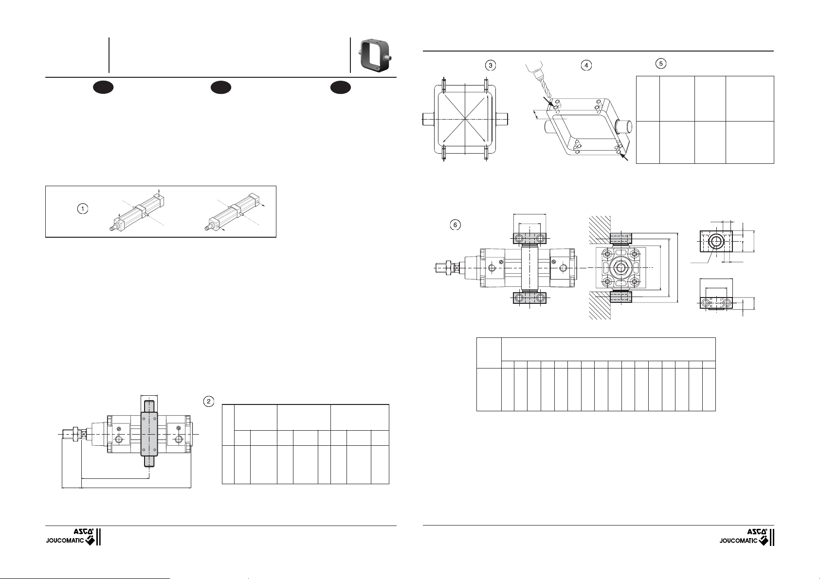
1- S'assurer que les axes du tourillon sont cor-
rectement orientés par rapport aux orifi ces
du vérin (voir fi g.1)
• Orientation standard: axe du tourillon
perpendiculaire aux orifi ces d'alimentation
du vérin (code 410 002)
•
L'autre position, sur demande: code 410 003
Fig.
Abb
2-Positionner le tourillon à l'emplacement
souhaité sur le tube (voir valeur mini et
maxi, pour vérin avec ou sans détecteur de
position suivant fi g. et tableau 2)
3- Serrer modérement et en croix, les 8 vis
pointeaux suivant fi g. 3
4- Desserrer une vis pointeau de chaque face
du tourillon (voir fi g.4)
5- Percer à travers les 2 trous libres du tou-
rillon avec un foret suivant spécifi cations du
tableau 5
6- Réintroduire les 2 vis pointeaux pour venir
tarauder le tube de façon à assurer un
blocage parfait entre le tube et la fi xation
ADAPTATION SUPPORTS TOURILLON
- Les supports de tourillon permettant
l'adaptati
on suivant fi g. 6
-
Graisser les axes du tourillon lors du montage.
A
410 002
XV
ZJ +
TK
C
Mise en service - Installation - Inbetriebnahme
GB
Fitting the MT4 centre trunnion on PES
cylinders allows a choice of position. The
centre trunnion slides along the barrel to allow on-site adjustment. For that reason, it is
delivered unlocked.
LOCKING THE CENTRE TRUNNION
1- Check that the axes of the spindle are cor-
rectly adjusted in relation to the cylinder
orifi ces (see fi g.1).
• Standard position:the axis of the centre
trunnion is perpendicular to the supply ports
of the cylinder (code 410 002).
•
Optional position, on request: code 410003
410 003
2-Adjust the centre trunnion to the desired
position
over the barrel (see min. and max. values
for cylinder with or without position
detector, following fi gure and table 2).
3- Slightly tighten crosswise the 8 locking
screws following fi gure 3.
4- Unscrew a locking screw on each side of
the centre trunnion (see fi g. 4).
5-Pierce the two free holes on the trunnion
with a drill in accordance with the specifi cations in table 5.
6- Re-insert the two locking screws and tighten
the trunnion to the barrel so as to ensure a
perfect tight fi t between the barrel and the
fastening.
MOUNTING SUPPORTS FOR CENTRE
TRUNNION
-
The supports enable mounting according
to
fi g. 6 .
- Grease the axes of the spindle before
mounting.
Fig.
Abb
Sans détecteurs
Without detectors
ohne Detektor
Ø
XV XV XV XV C XV XV C
min. max. min. max. min. min. max. min.
32 70 76 + C 114 32 + C 82 105 41 + C 130
40 79 86 + C 124 41 + C 83 114 51 + C 130
50 86 95 + C 132 49 + C 83 122 59 + C 130
63 96 115 + C 147 64 + C 83 138 73 + C 130
80 102 120 + C 155 67 + C 88 145 77 + C 130
100 109 131 + C 165 75 + C 90 156 84 + C 130
C = + Course C = + Stroke C = + Hub
Die Montage der Mittelschwenkbefestigung MT4
ermöglicht eine bewegliche Befestigung. Die
Schwenkbefestigung kann entlang des Rohres für
eine Positionierung vor Ort verschoben werden.
Deshalb wird sie bei Lieferung nicht fest auf dem
Rohr angezogen.
ANZIEHEN DER SCHWENKBEFESTIGUNG
1- Vergewissern Sie sich, daß die Achsen der
• Standardpositionierung: Die Achse der
• Andere Position auf Anfrage:
Bestell-Code 410 003
2-Positionieren Sie die Schwenkbefestigung an
3-Ziehen Sie die 8 Klemmschrauben gemäß Abb.
4-
5- Durchbohren Sie die zwei freien Löcher an
6- Setzen Sie die beiden Klemmschrauben
MONTAGE DER LAGER FÜR DIE SCHWENKBEFESTIGUNG
- Die Stützen ermöglichen eine Montage
gemäß Abb. 6.
- Schmieren Sie die Achsen der
Schwenkbefestigung bei der Montage.
Avec détecteurs "T"
With "T" detectors
mit "T" Detektor
DE
Schwenkbefestigung richtig zu den Zylinderanschlüssen hin orientiert sind (siehe Abb. 1).
Schwenkbefestigung ist senkrecht zu den
Anschlüssen des Zylinders ausgerichtet (Bestell-code 410 002).
die gewünschte Stelle am Rohr (siehe Mindestund Maximalwerte für Zylinder mit und ohne
Näherungsschalter anhand der Abbildung und
der Tabelle 2).
3 leicht über Kreuz an.
Lösen Sie je eine Klemmschraube auf jeder
Seite der Schwenkbefestigung (siehe Abb. 4).
der Schwenkbefestigung mit einem Bohrer
entsprechend den Angaben in Tabelle 5.
wieder ein und befestigen Sie die Schwenkbefestigung am Rohr derart, dass ein fester
Sitz zwischen Rohr und Befestigung gewährleistet ist.
Avec détecteurs "compact"
With "compact" detectors
mit "compact" Detektor
Fig.
Abb
1
3
Fig.
Abb
x
4
2
X = Profondeur de perçage maxi
X = maximum drilling depht
X = Maxdestbohrtiefe
Fig.
Abb
Ø Vis Ø percage
Ø
Ø Screw Drilling Ø
Vérin
Ø Schraube Ø Bohrung
Cylinder
(mm) (mm)
Zylinder
32 M5 4,6 15
40 M5 4,6 15
50 M6 5,5 18
63 M6 5,5 18
80 M8 7,5 25
100 M8 7,5 25
SUPPORTS DE TOURILLON - TRUNNION SUPPORTS - LAGER FÜR DIE SCHWENKBEFESTIGUNG
UL
==
Fig.
Abb
Ø
Alésages
Bore
Kolben
(mm)
32
40
50
63
80
100
TH
==
==
=
=
h14
L5
TM
=
=
H9
Ø CR
L6
COTES - DIMENSIONS - MASSE (mm)
A C CR Ød4 FK FN HB H3 L5 L6 NH TH TK TM UL ZJ
22 10,5 12 11 15 30 6,6 6,8 71 86 18 32 18 50 46 120
24 12 16 15 18 36 9 9 87 105 21 36 20 63 55 135
32 12 16 15 18 36 9 9 99 117 21 36 20 75 55 143
32 13 20 18 20 40 11 11 116 136 23 42 25 90 65 158
40 13 20 18 20 40 11 11 136 156 23 42 25 110 65 174
40 16 25 20 25 50 13,5 13 164 189 28,5 50 30 132 75 189
==
Ød4
UL
TH
Profondeur de
Drilling depht
Ø HB
==
perçage
Bohrtiefe
(mm)
H3
FN
FK
NH
C
==
(383 47 86)
MS-P229-8
Page 2

Serie 453
Type: PES P-DM
CERNIERA CENTRALE MT4 su CILINDRI PES A CANNA PROFILATA
CHARNELA MACHO para CILINDROS PES CON TUBO PERFILADO
ZWENKTAP MT4 OP PES CILINDERS MET PROFIELBUIS
IT
Il fi ssaggio con cerniera centrale MT4 permette
un montaggio oscillante. Questa cerniera scorre lungo la canna per consentire la regolazione
sul posto. A tal scopo, il cilindro viene fornito
con la cerniera non bloccata sulla canna.
SERRAGGIO DELLA CERNIERA
1- Assicurarsi che i perni della cerniera siano
correttamente orientati rispetto ai fori di
alimentazione del cilindro (vedere fi g.1)
• Or ientazione standard: perno della cerniera
perpendicolare ai fori di alimentazione del
cilindro (codice 410 002)
• Altra posizione, a richiesta: cod. 410 003
410 002
Fig.
2-Posizionare la cerniera nella posizione voluta
sulla canna (vedere i valori min. e max. per
cilindro con o senza fi ne corsa secondo la
fi g. e la tabella 2)
3- Stringere leggermente e a croce le 8 viti a
brugola come da fi g. 3
4- Togliere una vite a brugola da ogni lato della
cerniera (vedere fi g.4)
5- Perforare i 2 fori liberi della cerniera se-
guendo le istruzioni della tabella 5
6- Reinserire le 2 viti a brugola per fi lettare la
canna in modo da assicurare un bloccaggio
perfetto tra la canna ed il fi ssaggio.
SUPPORTI DI MONTAGGIO PER CERNIERA CENTRALE
-
I supporti della cerniera centrale permetto
no il montaggio come da fi g. 6
- Lubrifi care i perni della cerniera all'atto del
montaggio.
TK
XV
A
ZJ +
C
Montaggio - Instalación - Installatie
ES
La fi jación por charnela MT4 per mite un montaje oscilante. Esta charnela se desliza a lo
largo del tubo permitiendo la regulación de la
posición in situ. Por este motivo se suministra
sin bloquear sobre el tubo.
APRIETE DE LA CHARNELA
1- Asegurarse de que los ejes de la charnela
están correctamente orientados con respecto a los orifi cios del cilindro (ver fi g. 1).
• Orientación standard : eje de la charnela
perpendicular a los orifi cios de alimentación
del cilindro (código 410 002).
• La otra posición bajo demanda : código
410 003.
410 003
2-Posicionar la charnela en el emplazamiento
deseado sobre el tubo (ver valores mínimo
y máximo, para cilindro con o sin detector
de posición según fi g. y cuadro 2).
3-Apretar moderadamente y en cruz, los 8
tornillos según fi g. 3.
4- Desenroscar un prisionero de cada cara de
la charnela (ver fi g.4)
5- Taladrar hasta atravesar los 2 orifi cios
libres de la charnela con una broca según
especifi caciones del cuadro 5
6- Reintroducir los 2 prisioneros autoroscando
en el tubo, de forma que estos 2 queden
alojados entre el tubo y la charnela, asegurando así un bloqueo perfecto.
ADAPTACION DE LOS SOPORTES DE LA
CHARNELA
- Los soportes de charnela que permiten su
adaptación como aparece en la fi g. 6.
- Engrasar los ejes de la charnela al realizar
el montaje.
Fig.
Senza fi ne corsa
Sin detectores
zonder schakelaars
Ø
XV XV XV XV C XV XV C
min. max. min. max. min. min. max. min.
32 70 76 + C 114 32 + C 82 105 41 + C 130
40 79 86 + C 124 41 + C 83 114 51 + C 130
50 86 95 + C 132 49 + C 83 122 59 + C 130
63 96 115 + C 147 64 + C 83 138 73 + C 130
80 102 120 + C 155 67 + C 88 145 77 + C 130
100 109 131 + C 165 75 + C 90 156 84 + C 130
C = + Corsa C = + Carrera C = + slag
NL
De montage van de zwenktap MT4 kan naar
eigen keuze geschieden. De positie van de
zwenktap kan over de gehele lengte van de
cilinderbuis naar keuze bepaald worden.
Daarom wordt deze ook los meegeleverd.
BEVESTIGING VAN DE ZWENKTAPPEN
1- Controleer of de assen van zwenktappen juist
zijn gepositioneerd in relatie tot de poorten
van de cilinder. (zie afb. 1.)
• Standaardpositionering: De As van de
zwenktap staat loodrecht op de poorten van
de cilinder. (bestelnummer 410 002).
• Andere posities zijn op aanvraag
verkrijgbaar: bestelnummer 410 003
2-Positioneer de zwenktap in de gewenste stand
langs de cilinderbuis (zie min. en max. waarden
voor een cilinder met of zonder magnetische
eindschakelaar, volgens fi g. 2 en de daarbij
behorende tabel).
3-Draai de 8 klemschroeven zachtjes kruislings
aan conform fi g. 3.
4- Draai een bout los aan iedere zijde van de tap
(zie pagina 4).
5- Boor door de 2 vrije gaten van de tap met
een boormachine volgens de specifi caties
van tabel 5.
6- Steek de 2 bouten er weer in om de buis zo
te tappen dat een volledige blokkering wordt
gegarandeerd tussen de buis en de bevestiging.
BEVESTIGINGSSTEUNEN VOOR DE
ZWENKTAP
- De bevestigingssteunen die montage volgens
fi g. 6 mogelijk maakt.
- Vet de assen van de zwenktap in alvorens
deze te monteren.
Con fi ne corsa
Con detectores
met schakelaars
"T"
"T"
"T"
Con fi ne corsa
Con detectores
met schakelaars
"compact"
"compact"
"compact"
Fig.
1
3
Fig.
x
4
2
X = profondita di foratura max.
X = profundidad de taladro max.
X = max. boordiepte
Fig.
Ø Vite Ø Foratura
Ø
Ø Tornillo Ø Taladro
Cilindro
Ø Schroef Ø Boorgat
Cilinder
(mm) (mm)
32 M5 4,6 15
40 M5 4,6 15
50 M6 5,5 18
63 M6 5,5 18
80 M8 7,5 25
100 M8 7,5 25
SUPPORTI CERNIERA - SOPORTES DE CHARNELA - ZWENKTAP BEVESTIGINGEN
UL
==
Fig.
Ø
Alesaggio
Diámetros
Boring
(mm)
32
40
50
63
80
100
TH
==
h14
TM
DIMENSIONI - COTAS - AFMETINGEN (mm)
A C CR Ød4 FK FN HB H3 L5 L6 NH TH TK TM UL ZJ
22 10,5 12 11 15 30 6,6 6,8 71 86 18 32 18 50 46 120
24 12 16 15 18 36 9 9 87 105 21 36 20 63 55 135
32 12 16 15 18 36 9 9 99 117 21 36 20 75 55 143
32 13 20 18 20 40 11 11 116 136 23 42 25 90 65 158
40 13 20 18 20 40 11 11 136 156 23 42 25 110 65 174
40 16 25 20 25 50 13,5 13 164 189 28,5 50 30 132 75 189
Profondita di
foratura
Profundidad de
taladro
Boordiepte
(mm)
Ød4
==
=
=
L5
=
=
H9
Ø CR
L6
UL
==
TH
H3
FN
==
FK
Ø HB
==
NH
C
 Loading...