

ASCO ASCO Series NFIS WSNFIS low power solenoids | Installation & Maintenance Manuals & Guides
2
7
1
3
4
10
11
9
6
8
12
5
Intrinsically safe/low power solenoid operator (NFIS / WSNFIS - MXX)
This installation and maintenance instruction sheet
of the solenoid is a general supplement to the
particular I&M sheet for the valve. The identication is made by prex (WS)NFIS to the catalogue
number. Always use both I&M sheets for installing
and maintaining the solenoid valve.
The ‘IS’-solenoids are designed in accordance with
Annex II of the European Directive 2014/34/EU and
IEC standards:
ATEX IECEx
EN ISO 80079-36
EN ISO 80079-37
EN 60079-0 IEC 60079-0
EN 60079-11 IEC 60079-11
EN 60079-31 IEC 60079-31
(WS)NFIS
Classication:
II 2G Ex ia IIC T6 Gb
II 2D Ex tb IIIC T85°C Db IP66/67
Special Conditions for safe use:
ASCO™ components are intended to be used only
within the technical characteristics as specied on
the nameplate. Changes to the equipment are only
allowed after consulting the manufacturer or its representative. The solenoid valve must be supplied
with power from a voltage barrier certied for use
in potentially explosive atmospheres of groups IIC,
IIB and IIA and having an output circuit that is rated
intrinsically safe. The valve-and-barrier combination
must be compatible in terms of intrinsic safety.
The voltage barrier for the equipment must have
the following maximum characteristics: Uo=32V;
Io=500mA and Po=1,5W. Selecting the barrier
and making the interconnections are at the user’s
responsibility. The operating temperature range is
-40°C to +60°C.
temp.
for dust
(°C) T (°C) (W) (°C)
85 6 60 1,5 -
GENERAL
DESCRIPTION
INSTALLATION
surface temperature
classication (G/D)
temp.
max.
class.
ambient
temp.
max. cold
wattage
DC
cable
temp.
(G/D)
max.
cable
temp.
INSTALLATION AND MAINTENANCE INSTRUCTIONS
ELECTRICAL INSTALLATION
Wiring must comply with local and national regulations of explosion proof equipment. Application of
the (WS)NFIS solenoid in the hazardous area is
not permitted without the addition of an approved
and classied device (such as barriers), located
between the safe and the hazardous area. The
purpose of the safety device is to protect the
equipment located within the hazardous area from
current and voltage surges, which might enter the
system from the energy sources located in the safe
area. In addition the wiring to the equipment installed within the hazardous location should satisfy
particular requirements with respect to resistance
(R), inductance (L), capacitance (C), inductance to
resistance ratio (L/R) and screening. Due to redundant blocking diodes the eective internal inductance and capacitance of the solenoid are neglibly
small. To make connection to the coil terminals,
remove solenoid cover. Strip the outer insulation of
the cable over approx. 150 mm and the insulation
from the leads over 8 mm. Insert wires through the
cable gland or conduit hub and connect wires to
the terminals of the coil. Connect cable ground wire
to the internal ground terminal. Keep some slack
in the leads between cable entry and coil to avoid
excessive strain on the leads. Assemble the cable
gland and tighten the elastomer compression seal
so that it ts tightly around the cable.
CAUTION: In order to obtain IP66/67 with a metal
cable gland (torque 7Nm), it is necessary to put
graphite grease on 1/2” NPT threads according to
standard IEC-EN 60079-14.
When the set screw is unscrewed, the solenoid
can be rotated 360° to select the most favorable
position for the cable entry. Close the enclosure
and tighten 4 cover screws securely to torque
indicated. The solenoid housing is provided with
an external connection facility for an earthing or
bonding conductor.
NOTE: Standard cable gland accepts
cables with overall O.D. from 7 to 12
mm. IP66/67: Tighten the cable gland
with a torque of min. 8 Nm. Use of plastic cable gland is limited to equipment
category 2G only.
ELECTRICAL SPECIFICATIONS
Nominal operating voltage range - 24 VDC +/- 10%.
Minimum nominal current: 32mA. Nominal power:
0,5W. Minimum series resistance required - 200
Ohms. Maximum allowable system leakage current - 1 mA.
Pn
Ui (DC) IiPiLiC
(W) (V) (mA) (W) (mH) (μF)
0,5 32 500 1,5 0 0
Intrinsically Safe Coil Calculations
The following application information will allow
the calculation of the loop current for the ASCO™
intrinsically safe solenoid.
Denitions:
= The supply voltage to the barrier.
V
supply
T
= The ambient temperature in degrees C.
ambien
t
= The maximum barrier end to end resistance.
R
barrier
= The maximum resistance in lead wire
R
loop
=
R
The resistance of the solenoid coil at T
coil
R
coil
I
loop
I
loop
This current must always be greater than or equal
to 32mA for proper operation of the solenoid valve.
Electrical load must be within the range stated on
the nameplate. Failure to stay within the electrical
range of the coil rating results in damage to or
premature failure of the coil. It will also invalidate
the approval.
To prevent the possibility of personal or property
damage, do not touch the solenoid. It can become
hot under normal operation conditions. If the solenoid valve is easily accessible, the installer must
provide protection preventing accidental contact.
(T
amb
= 32 Ω
254
= Loop current in the circuit:
(V
supply
=
(54 + R
+ R
coil
Safety Parameters
+ 234)
- 3.2)
+ R
loop
barrier
CAUTION
SERVICE
ambient
r
PREVENTIVE MAINTENANCE
Maintenance depends on service conditions. Periodic cleaning is recommended, the timing of which
will depend on the media and service conditions. If
a problem occurs during installation/maintenance
or in case of doubt please contact Emerson or authorized representative. Keep the medium owing
through the valve as free as possible from dirt and
i
foreign material.
For additional information visit our website:
Emerson.com/ASCO
q
GB
)
123620-356 Rev.C ECN 298891
Page 1 of 6
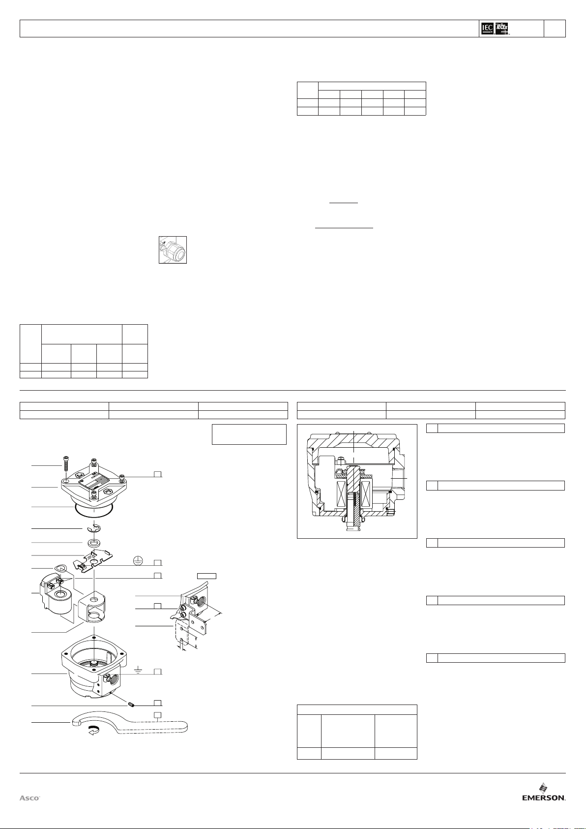
DRAWING DESSIN ZEICHNUNG
DISEGNO TEKENING
SERIES
NFIS/WSNFIS-MXX
A
B
C
TOP
13
E
14
15
B
B
D
DIN 1810 -A 80-90
OPTIONAL
51
25
Ø6,5
Modication date 2020-01-16
DRAWING DESSIN ZEICHNUNG
DISEGNO TEKENING
TORQUE CHART
A
B
C
D
E
ITEMS NEWTON.METRES INCH.POUNDS
www.emerson.com/asco
7±0,5
1±0,2
0,5±0,1
20±3
4±0,5
62±5
8±2
4±1
175±25
35±5
GB DESCRIPTION
1. Screw
2. Cover
3. O-ring
4. Clip
5. Spacer (optional)
6. Plate
7. Washer, spring
8. Coil
9. Yoke
FR DESCRIPTION
1. Vis
2. Couvercle
3. Joint torique
4. Clip
5. Bague d’espacement (en
option)
6. Plaque
7. Rondella élastique
8. Bobine
DE BESCHREIBUNG
1. Schraube
2. Deckel
3. Dichtungsring
4. Klammer
5. Distanzstück (optional)
6. Platte
7. Federscheibe
8. Magnetspule
9. Joch
IT DESCRIZIONE
1. Vite
2. Coperchio
3. Anello di ritenuta
4. Clip
5. Distanziale (facoltativo)
6. Targhetta
7. Rondella elastica
8. Bobina
9. Giogo
NL BESCHRIJVING
1. Bout
2. Deksel
3. O-ring
4. Bevestigingsclip
5. Opvulring (optie)
6. Plaat
7. Veerring
8. Spoel
9. Juk
10. Housing
11. Set screw
12. Hook wrench
13. Washer, spring (2x)
14. Screw (2x)
15. Mounting bracket
9. Culasse
10. Boîtier
11. Vis de l’ensemble
12. Clé à crochet
13. Rondella élastique (2x)
14. Vis (2x)
15. Support de montage
10. Gehäuse
11. Einstellschraube
12. Hakenschlüssel
13. Federscheibe (2x)
14. Schraube (2x)
15. Montagehalterung
10. Sede
11. Vite di fermo
12. Chiave per dadi
13. Rondella elastica (2x)
14. Vite (2x)
15. Squadra di ssaggio
10. Huis
11. Stelschroef
12. Haaksleutel
13. Veerring (2x)
14. Schroef (2x)
15. Montagebeugel
INSTRUCTIONS D’INSTALLATION ET DE MAINTENANCE
Tête magnétique à tension basse/renforcée intrinsèquement
Cette feuille d’instructions d’installation et de maintenance du
solénoïde constitue un supplément d’ensemble à la feuille particulière I&M de l’électrovanne. L’identication est eectuée en faisant
précéder le préxe (WS)NFIS devant le numéro de catalogue.
Reportez-vous aux feuilles I&M lors de l’installation et de la maintenance de l’électrovanne valve.
Les têtes magnétiques ‘IS’sont conformes l’Annexe II de la Directive
européenne 2014/34/EU et les normes du IEC:
ATEX IECEx
EN ISO 80079-36
EN ISO 80079-37
EN 60079-0 IEC 60079-0
EN 60079-11 IEC 60079-11
EN 60079-31 IEC 60079-31
(WS)NFIS
Classication: II 2G Ex ia IIC T6 Gb
II 2D Ex tb IIIC T85°C Db IP66/67
Conditions spéciales pour une utilisation en toute sécurité:
Les composants ASCO™ sont conçus pour les domaines de fonctionnement indiqués sur la plaque signalétique ou la documentation.
Aucune modication ne peut être réalisée sur le matériel sans l’accord préalable du fabricant ou de son représentant. L'électrovanne
doit être alimentée à partir d'une barrière de tension certiée pour
une utilisation dans les atmosphères explosibles des groupes IIC, IIB
et IIA et doit avoir un circuit de sortie reconnu de sécurité intrinsèque.
Leur association doit être compatible du point de vue de la sécurité
intrinsèque. La source de tension, pouvant alimenter le matériel,
possède les caractéristiques maximales suivantes : Uo=32V ; Io=500mA et Po=1,5W. Le choix de la barrière ainsi que la réalisation
des interconnexions sont de la responsabilité de l’utilisateur. La
plage de températures de fonctionnement va de -40°C à +60°C.
temp.
pour la
poussière
(°C) T (°C) (W) (°C)
Le câblage doit être conforme à la réglementation locale et nationale
en matière d’installation d’équipement antidéagrant. L’application
du solénoïde (WS)NFIS dans la zone à risque n’est pas autorisée
sans avoir placé préalablement un équipement agréé et classé
(tel que des barrières), situé entre la zone sécurisée et la zone à
risque. L’objectif de l’équipement de sécurité vise à protéger les
appareils placés dans la zone à risque contre tout courant transitoire anormal et surtension, qui pourrait pénétrer dans le système
depuis les sources d’énergie situées dans la zone sécurisée. En
outre, le câblage eectué sur l’équipement installé dans la zone à
risque devrait respecter des exigences particulières relatives à la
résistance (R), l’inductance (L), la capacitance (C), l’inductance au
ratio de résistance (L/R) et le ltrage. Grâce à des diodes de blocage
redondantes, l’inductance et la capacitance interne eective du
solénoïde sont très faibles. Pour raccorder les bornes de la bobine,
enlever le couvercle du solénoïde. Dénudez environ 150 mm de
l’extrémité de l’isolant extérieur du câble et l’isolant des ls sur 8
mm. Insérez les câbles dans le presse-étoupe ou l’entrée du conduit
et raccordez les câbles aux bornes de la bobine. Raccordez le l
de mise à la terre du câble à la borne interne de la mise à la terre.
Maintenez un certain écart au niveau des ls situés entre l’entrée
du câble et la bobine an d’éviter toute contrainte excessive sur les
ls. Assemblez le presse-étoupe et serrez le joint de compression
de l’élastomère de sorte qu’il serre de façon appropriée le câble.
classement de températures
temp.
class.
85 6 60 1,5 -
INSTALLATION ELECTRIQUE
(NFIS / WSNFIS - MXX)
GENERALITES
DESCRIPTION
INSTALLATION
de surface (G/D)
temp. max.
ambiante
tension froide
max.
CC
temp. câble
(G/D)
temp. câble
max.
r
q
REMARQUE : Le presse-étoupe standard accepte
des câbles de diamètre global de 7 - 12 mm. Serrez le
presse-étoupe avec un couple de 8 Nm min. L'utilisation
d'un presse-étoupe en plastique se limite à la catégorie
de l'équipement 2G.
ATTENTION : Pour obtenir IP66/67 avec un presse-étoupe métallique (couple 7Nm), il faut mettre de la graisse graphite sur les
letages n 1/2” NPT conformément à la norme IEC-EN 60079-14.
Lorsque le boulon de maintien est dévissé, il est possible de
tourner le solénoïde de 360° pour sélectionner la position la plus
favorable pour l’entrée de câble. Bien serrer le boulon de maintien
et fermer l’enveloppe. Le couvercle de la tête magnétique est livré
avec des raccordements externes pour conducteur à la terre et
de raccordement.
CARACTERISTIQUES TECHNIQUES ELECTRIQUES
Gamme de tension nominale de fonctionnement - 24 VCC +/- 10%.
Courant minimum nominal : 32mA. Puissance nominale : 0,5 W.
Résistance série minimum exigée - 200 Ohms. Courant de fuite du
système admissible maximum - 1 mA.
Pn
(W) (V) (mA) (W) (mH) (μF)
0,5 32 500 1,5 0 0
Calculs de bobine intrinsèquement sécurisés
Les informations suivantes sur l’application permettent le calcul
du courant de boucle pour le solénoïde intrinsèquement sécurisé.
Dénitions:
= La tension d’alimentation vers la barrière.
V
supply
= La température ambiante en degrés C.
T
ambient
= La résistance de bout en bout maximum de la barrière.
R
barrier
= La résistance maximum du l de plomb
R
loop
=
R
La résistance de la bobine de l’électrovanne à T
coil
= 32 Ω
R
coil
= Courant de boucle dans le circuit:
I
loop
=
I
loop
Ce courant doit toujours être égal ou supérieur à 32mA pour un fonctionnement correct de l’électrovanne.
La charge électrique doit être comprise dans la gamme qui gure sur
la plaque signalétique. Tout manquement au respect de la gamme
électrique du classement de la bobine risque d’endommager la bobine
ou de provoquer sa défaillance. Cela annulera également l’agrément.
Pour éviter tout risque d’accidents ou de détérioration, ne pas toucher
le solénoïde. Il peut produire un fort dégagement thermique dans des
conditions normales de fonctionnement. Si l’électrovanne est facilement
accessible, l’installateur doit prévoir une protection empêchant tout
contact accidentel.
La maintenance dépends des conditions de service. Il est souhaitable
de procéder à un nettoyage périodique dont l’intervalle varie suivant
la nature du uide, les conditions de fonctionnement et le milieu
ambiant. Si un problème survient lors de l'installation / entretien ou
en cas de doute, s'il vous plaît contactez Emerson ou autoriser des
représentants. Gardez le liquide le plus libre possi de la saleté et
substances étrangères.
Pour toute information complémentaire, veuillez consulter notre
site Web: Emerson.com/ASCO
Paramètres de sécurité
Ui (DC) I
i
(T
+ 234)
amb
254
(V
- 3.2)
supply
(54 + R
+ R
+ R
)
coil
loop
barrier
ATTENTION
SERVICE
MAINTENANCE PREVENTIVE
PiLiC
FR
i
ambient
BETRIEBSANLEITUNG
Erhöhte Sicherheit / Vergußgekapselter Magnetkopf
Diese Betriebsanleitung für den Magnetkopf ist ein allgemeiner
Nachtrag zur spezischen Betriebsanleitung für dieses Ventil. Die
Identizierung erfolgt durch den Vorsatz (WS)NFIS, der der Katalognummer vorangestellt wird. Bei der Installation und Wartung des
Magnetventils sind immer beide Betriebsanleitungen heranzuziehen.
Die Magnetköpfe des Typs ‘IS’ erfüllen die europäische Richtlinie
2014/34/EU Anhang II sowie die Normen des Europäischen Komitees
für elektrotechnische Normung (IEC) und besitzen die Zulassung
von KEMA (Niederlande).
ATEX IECEx
EN ISO 80079-36
EN ISO 80079-37
EN 60079-0 IEC 60079-0
EN 60079-11 IEC 60079-11
EN 60079-31 IEC 60079-31
(WS)NFIS
Nach Zündschutzart: II 2G Ex ia IIC T6 Gb
II 2D Ex tb IIIC T85°C Db IP66/67
Besondere Bedingungen für den sicheren Gebrauch:
Die ASCO™-Komponenten dürfen nur innerhalb der auf den Typenschildern angegebenen Daten eingesetzt werden. Veränderungen
an den Produkten sind nur nach Rücksprache mit Emerson zulässig.
Das Magnetventil muss von einer Spannungsbarriere mit Strom
versorgt werden, die für die Verwendung in potenziell explosionsgefährdeten Atmosphären der Gruppen IIC, IIB und IIA zertiziert
ist und einen Ausgangskreis hat, der als eigensicher eingestuft ist.
Die Kombination aus Ventil und Barriere muss den Bedingungen der
intrinsischen Sicherheit entsprechen. Die Spannungsbarriere für das
Gerät muss die folgenden maximalen Eigenschaften haben: Uo = 32
V; Io = 500 mA und Po = 1,5 W. Für die Auswahl der Barriere und
die Vornahme der Verbindungen ist der Benutzer verantwortlich. Der
Betriebstemperaturbereich ist -40° C bis +60° C.
Temp. für
Staub
(°C) T (°C) (W) (°C)
Die Verdrahtung muß den örtlichen und nationalen Vorschriften für
exgeschützte Geräte entsprechen. Der Einsatz des Magnetkopfs
(WS)NFIS in gefährlichen Zonen ist nur durch zusätzlichen Einbau
einer zugelassenen und klassizierten Vorrichtung (wie z.B. Barrieren) zwischen der sicheren und der gefährlichen Zone zulässig.
Zweck der Sicherheitsvorrichtung ist es, das in der gefährlichen Zone
angeordnete Gerät vor Strom- und Spannungsstößen zu schützen,
die eventuell ausgehend von den in der sicheren Zone angeordneten
Energiequellen auf das System einwirken. Darüber hinaus muß die
Verdrahtung zu dem in der gefährlichen Zone installierten Gerät
spezielle Anforderungen in bezug auf Widerstand (R), Induktivität (L),
Kapazität (C), Verhältnis zwischen Induktivität und Widerstand (L/R)
und Abschirmung erfüllen. Aufgrund der redundanten Sperrdioden
ist die eektive interne Induktivität und Kapazität des Magnetskopfs
vernachlässigbar gering. Zum Anschließen an die Spulenklemmen
muß der Magnetkopfdeckel abgenommen werden. Äußere Isolierung des Kabels auf ca. 150 mm und Isolierung der Drähte auf ca.
8 mm abziehen. Drähte durch die Kabelverschraubung oder den
Kabelanschluß einführen und an die Spulenklemmen anschließen.
Erdungsdraht des Kabels an die interne Erdungsklemme anschließen. Kabelenden zwischen Kabeleinführung und Spule nicht stra
ziehen, um eine übermäßige Zugbeanspruchung an den Kabelenden
zu vermeiden. Kabelverschraubung zusammenbauen und Dichtung
aus Elastomer so anziehen, daß sie das Kabel fest umschließt.
Oberächentemperatur (G/D)
Temp.-Klasse max.
85 6 60 1,5 -
ELEKTRISCHE INSTALLATION
(NFIS / WSNFIS - MXX)
ALLGEMEINES
BESCHREIBUNG
INSTALLATION
Klassizierung der
Umgebungs-
temp.
max. kalte
Wattzahl
Gleichstrom
Kabeltemp.
(G/D)
max. Kabeltemperatur
r
q
DE
HINWEIS: Die Standard-Kabelverschraubung ist für
Kabel mit einem Außendurchmesser von 7 bis 12 mm
geeignet. IP66/67: Ziehen Sie die Kabelverschraubung
mit einem Moment von mind. 8 Nm an. Die Verwendung
von Kunststo-Kabelverschraubungen ist die Geräte-
kategorie 2G begrenzt.
VORSICHT: Um IP66/67 bei einer Metall-Kabelverschraubung
(Moment 7 Nm) zu erhalten, ist es erforderlich, Grat-Schmierfett
auf die 1/2” NPT-Gewinde gemäß dem Standard IEC-EN 6007914 aufzubringen.
Nach dem Lösen der Sicherungsmutter ist der Magnetkopf um
360° drehbar, so daß die günstigste Position für die Kabeleinführung gewählt werden kann. Sicherungsmutter fest anziehen
und Gehäuse schließen. Das Magnetkopfgehäuse ist mit einer
externen Anschlußvorrichtung für einen Erdungs- oder Potentialausgleichsleiter versehen.
Nennbetriebsspannungsbereich - 24 V= +/- 10%. Minimaler
Nennstrom: 32mA. Nennleistung: 0,5 W. Erforderlicher
Mindestreihenwiderstand -200 Ohm. Maximal zulässiger
Systemleckstrom -1 mA.
Pn
(W) (V) (mA) (W) (mH) (μF)
0,5 32 500 1,5 0 0
Berechnung der eigensicheren Spule
Anhand der folgenden Anwendungsdaten kann der Schleifenstrom
für den eigensicheren ASCO™ Magnetkopf ermittelt werden.
Denitionen:
V
supply
T
ambient
R
barrier
R
loop
R
coil
R
coil
I
loop
I
loop
Dieser Strom muß immer größer als oder gleich 32mA sein, um einen
korrekten Betrieb des Magnetventils zu gewährleisten.
Die elektrische Belastung muß in dem auf dem Typenschild angegebenen Bereich liegen. Wird der elektrische Bereich der Spule
nicht beachtet, so kann dies zur Beschädigung oder zum frühzeitigen
Ausfall der Spule führen. Außerdem erlischt dadurch die Zulassung.
Zur Vermeidung von Personen- und Sachschäden sollte jede Berührung des Magnetkopfs vermieden werden, da dieser unter normalen
Betriebsbedingungen sehr heiß werden kann. Bei leicht zugänglichem Magnetventil sollte vom Installateur ein Schutz vorgesehen
werden, um jegliches versehentliches Berühren zu vermeiden.
Die Wartung hängt von den Betriebsbedingungen ab. Es wird
empfohlen, das Produkt regelmäßig zu reinigen, wobei sich die
Zeitabstände nach dem Medium und den Betriebsbedingungen
richten. Treten Schwierigkeiten bei Einbau, Betrieb oder Wartung
auf sowie bei Unklarheiten, ist mit Emerson Rücksprache zu halten.
Halten Sie das Medium durch das Ventil ießt so frei wie möglich
von Schmutz und Fremdkörpern.
Weitere Informationen finden Sie auf unserer Webseite:
Emerson.com/ASCO
ANSCHLUSSWERTE
Ui (DC) I
= Versorgungsspannung zur Barriere.
= Umgebungstemperatur in Grad Celsius.
= Maximaler End-zu-End-Widerstand der Barriere.
= Maximaler Widerstand des Kabeldrahts.
=
Widerstand der Magnetspule bei T
= 32 Ω
= Schleifenstrom im Stromkreis:
=
(54 + R
Sicherheitsparameter
PiLiC
i
(T
+ 234)
amb
254
(V
- 3.2)
supply
+ R
+ R
)
coil
loop
barrier
VORSICHT
BETRIEB
PRÄVENTIVWARTUNG
ambient
i
ISTRUZIONI DI INSTALLAZIONE E MANUTENZIONE
Testa magnetica a sicurezza intrinseca e basso consumo
Questa scheda di installazione e manutenzione della solenoide è il
supplemento generale alla scheda I & M dettagliata per la valvola.
L’identicazione viene realizzata mediante l’aggiunta del presso
(WS)NFIS al numero di catalogo. Per l’installazione e la manutenzione della valvola solenoide, usare sempre entrambe le schede I&M.
Le solenoidi ‘IS’ sono state progettate secondo l’Allegato II della
Direttiva europea 2014/34/EU e gli standard:
ATEX IECEx
EN ISO 80079-36
EN ISO 80079-37
EN 60079-0 IEC 60079-0
EN 60079-11 IEC 60079-11
EN 60079-31 IEC 60079-31
(WS)NFIS
Classicazione: II 2G Ex ia IIC T6 Gb
II 2D Ex tb IIIC T85°C Db IP66/67
Condizioni speciali per un utilizzo sicuro:
Le elettrovalvole ASCO™ devono essere utilizzate esclusivamente
rispettando le caratteristiche tecniche specicate sulla targhetta.
Variazioni sulle elettrovalvole sono ammissibili solo dopo avere
consultato il costruttore o il suo rappresentante. L'elettrovalvola deve
essere alimentata da una barriera di tensione certicata per l'uso in
atmosfere potenzialmente esplosive dei gruppi IIC, IIB e IIA e con
un circuito di uscita a sicurezza intrinseca. La combinazione valvola/
barriera deve essere compatibile in termini di sicurezza intrinseca.
La barriera di tensione per il componente deve avere le seguenti
caratteristiche massime: Uo=32V; Io=500mA e Po=1,5W. La scelta
della barriera di tensione e la realizzazione delle interconnessioni
sono compiti dell'utilizzatore. L'intervallo di temperatura nominale
è compreso fra -40°C e +60°C.
temp. per
classicazione temperatura in supercie (G/D) Temp. cavo
polvere
class. temp. temp. max.
(°C) T (°C) (W) (°C)
85 6 60 1,5 -
Il cablaggio deve soddisfare le normative locali e nazionali delle
apparecchiature antideagranti. L’applicazione della solenoide
(WS)NFIS in zone a rischio non è consentita senza l’aggiunta di un
dispositivo approvato e classicato (tipo barriere), posto tra la zona
sicura e quella a rischio. Lo scopo del dispositivo di sicurezza è quello
di proteggere le apparecchiature che si trovano nella zona a rischio
da sovracorrenti che potrebbero entrare nell’impianto dalle sorgenti
di energia che si trovano nella zona sicura. Inoltre, il cablaggio delle
apparecchiature installate nell’ambito della postazione a rischio
devono rispettare particolari requisiti in quanto a resistenza (R),
induttanza (L), capacitanza (C), induttanza al rapporto di resistenza
(L/R) e schermaggio. A causa dei diodi di bloccaggio ridondanti,
l’induttanza interna eettiva e la capacitanza della solenoide sono
trascurabili. Per eettuare la connessione ai morsetti della bobina,
togliere il coperchio della solenoide. Spelare l’isolante esterno del
cavo di circa 150 mm e l’isolante dai conduttori di 8 mm. Inserire i
li attraverso la tenuta del cavo lo spinotto del condotto e collegare
i connettori ai morsetti della bobina. Collegare il lo di terra del cavo
al morsetto di terra interno. Lasciare un certo gioco nei conduttori
tra l’ingresso del cavo e la bobina onde evitare un eccessivo stiramento dei conduttori stessi. Montare la tenuta del cavo e stringere
la guarnizione di compressione in elastomero in modo che aderisca
bene attorno al cavo.
123620-356 Rev.C ECN 298891
Page 2 of 6
INSTALLAZIONE ELETTRICA
NOTA: Il passacavo standard accetta cavi con un
diametro esterno totale da 7 a 12 mm. IP66/67: Serrare
il passacavo con una coppia di almeno 8 Nm. L'uso di
passacavi in plastica è limitato solo alla categoria di
apparecchi 2G.
(NFIS / WSNFIS - MXX)
GENERALE
DESCRIZIONE
INSTALLAZIONE
amb.
potenza
fredda max.
DC
(G/D)
temp. max.
cavo
r
q
IT
ATTENZIONE: Per ottenere il grado di protezione IP66/67 con un
passacavo in metallo (coppia 7Nm), è necessario applicare del
grasso alla grate su lettature NPT da 1/2” secondo lo standard
IEC-EN 60079-14.
Una volta svitato il dado di tenuta, è possibile ruotare il solenoide
di 360° per scegliere la posizione più favorevole per l’ingresso del
cavo. Stringere saldamente il dado di tenuta e chiudere la chiusura.
La sede della solenoide è munita di raccordo esterno per conduttore
di terra o massa.
Range di tensione di funzionamento nominale – 24 VDC +/- 10%.
Corrente nominale minima: 32mA. Potenza nominale: 0,5W. Resistenza di serie minima richiesta - 200 Ohm. Corrente di dispersione
max. ammessa dal sistema: 1 mA.
Calcoli della bobina a sicurezza intrinseca
Le seguenti informazioni sull’applicazione consentiranno i calcoli della corrente di circuito per la solenoide a sicurezza intrinseca ASCO™.
Denizioni:
V
supply
T
ambient
R
barrier
R
loop
R
coil
R
coil
I
loop
I
loop
Per il corretto funzionamento della valvola solenoide, occorre che
questa corrente sia sempre superiore o uguale a 32mA.
La potenza elettrica deve rientrare nei valori di targa. Il mancato
rispetto dei valori elettrici della bobina può causare danni o usura
anticipata della bobina stessa. Inoltre, renderà nulla l’approvazione.
Al ne di evitare la possibilità di danni alle persone o alle cose, non
toccare la solenoide. Nelle normali condizioni di funzionamento
potrebbe scaldarsi. Se di facile accesso, l’elettrovalvola deve essere
protetta per evitare qualsiasi contatto accidentale.
La manutenzione dipende dalle condizioni di servizio. Questi
componenti devono essere puliti periodicamente. Il tempo che
intercorre tra una pulizia e l’altra varia a seconda delle condizioni di
funzionamento. Se si incontrano problemi durante l’installazione e la
manutenzione o se si hanno dei dubbi, consultare Emerson o i suoi
rappresentanti. Tenere il uido attraverso la valvola il più possibile
libero da sporcizia e detriti.
Per informazioni aggiuntive, visitate il nostro sito web:
Emerson.com/ASCO
SPECIFICHE ELETTRICHE
Pn
Ui (DC) I
(W) (V) (mA) (W) (mH) (μF)
0,5 32 500 1,5 0 0
= La tensione di alimentazione alla barriera.
= La temperatura ambiente espressa in gradi centigradi.
= La massima resistenza della barriera da un’estremità all’altra.
= La massima resistenza nel conduttore.
=
La resistenza della bobina solenoide a T
= 32 Ω
= Corrente di circuito:
=
(54 + R
Parametri di sicurezza
PiLiC
i
barrier
SERVIZIO
ambient
)
(T
+ 234)
amb
254
(V
- 3.2)
supply
+ R
+ R
coil
loop
ATTENZIONE
MANUTENZIONE PREVENTIVA
i
Modication date 2020-01-16
ALGEMENE INSTALLATIE- EN ONDERHOUDSINSTRUCTIES
Verhoogde veiligheid / ingekapselde magneetkop
(NFIS / WSNFIS - MXX)
Dit installatie- en onderhoudsblad van de magneetkop bevat slechts
algemene, aanvullende informatie op het betreende I&M-blad van
de afsluiter zelf. Het voorvoegsel (WS)NFIS op het catalogusnummer
geeft het type aan. Raadpleeg altijd beide I&M-bladen voor het
installeren en onderhouden van de magneetafsluiter.
De ‘IS’-magneetkoppen voldoen aan de normen van Bijlage II
van de Europese Richtlijn 2014/34/EU en aan de IEC-normen:
ATEX IECEx
EN ISO 80079-36
EN ISO 80079-37
EN 60079-0 IEC 60079-0
EN 60079-11 IEC 60079-11
EN 60079-31 IEC 60079-31
(WS)NFIS
Classicatie: II 2G Ex ia IIC T6 Gb
II 2D Ex tb IIIC T85°C Db IP66/67
Speciale voorwaarden voor een veilig gebruik:
ASCO™ producten mogen uitsluitend toegepast worden binnen de
op de naamplaat aangegeven specicaties. Wijzigingen zijn alleen
toegestaan na overleg met de fabrikant of haar vertegenwoordiger.
De magneetafsluiter moet worden gevoed met vermogen via een
vermogensbarrière die is gecerticeerd voor gebruik in potentieel
explosieve atmosferen (groepen IIC, IIB en IIA) en waarbij
gebruik wordt gemaakt van een uitgangscircuit dat als intrinsiek
veilig is geclassiceerd. De combinatie van afsluiter en barrière
moeten voor wat betreft intrinsieke veiligheid compatibel zijn. De
spanningsbarrière voor de apparatuur moet de volgende kenmerken
voor het maximum hebben: Uo=32V; Io=500mA en Po=1,5W. De
gebruiker is verantwoordelijk voor het selecteren van de barrière en
het maken van de aansluitingen. Het bereik van de werktemperatuur
ligt tussen -40°C en +60°C.
temp. voor
stof
(°C) T (°C) (W) (°C)
85 6 60 1,5 -
De bedrading moet voldoen aan de plaatselijke en nationale
voorschriften voor explosieveilige installaties. IS-magneetkoppen
moeten worden aangesloten op een specieke en gehomologeerde
elektrische voeding (via een barrière of interface) die is geïnstalleerd
in een ongevaarlijke zone. Het doel van deze beveiliging is het
voorkomen van stroom- en spanningspieken in de explosiegevaarlijke
omgeving, afkomstig van de voeding die zich in de ongevaarlijke zone
bevindt. Bovendien moet de bedradingswijze van de apparatuur in de
explosiegevaarlijke omgeving voldoen aan specieke normen voor
weerstand (R), zelnductie (L), elektrische capaciteit (C), de verhouding
tussen zelnductie en weerstand (L/R) en afscherming. Door toepassing
van redundante sperdiodes zijn de eectieve interne zelnductie en
de elektrische capaciteit van de magneetkop verwaarloosbaar klein.
Verwijder het magneetkopdeksel om de spoelaansluitingen te kunnen
maken. Verwijder circa 150 mm van de buitenste isolatiemantel op het
uiteinde van de kabel, en circa 8 mm van de isolatie van de aders.
Steek de aders door de kabel- of leidingdoorvoer en sluit de aders
op de spoel aan. Sluit de aardleiding van de kabel aan op de interne
aardaansluiting. Zorg ervoor dat de aders voldoende speling hebben
tussen het kabelinvoerpunt en de spoelaansluitingen, om te voorkomen
dat er mechanische spanning op de aders kan komen te staan. Monteer
de kabeldoorvoer en draai de drukmoer voldoende vast om de exibele
afdichting strak om de kabel te klemmen.
www.emerson.com/asco
ALGEMEEN
BESCHRIJVING
INSTALLATIE
classicatie oppervlaktetemperatuur (G/D) Kabeltemp.
klass. temp. max.
ELEKTRISCHE INSTALLATIE
omgeving
temp.
max. wattage
koud
(G/D)
max.
kabeltemp.
DC
r
q
NL
OPMERKING: De standaardkabeldoorvoer is geschikt
voor kabels met een uitwendige diameter tussen 7 en
12 mm. IP66/67: Draai de kabeldoorvoer aan met een
aandraaikoppel van min. 8 Nm. Het gebruik van een
plastic kabeldoorvoer is alleen beperkt tot apparatuur categorie 2G.
LET OP: Om IP66/67 met een metalen kabeldoorvoor (aandraaikoppel
7 Nm) te verkrijgen, moet graetvet worden aangebracht op de
1/2 inch NPT-schroefdraden in navolging van de norm IEC-EN
60079-14.
Draai de bevestigingsmoer los zodat de magneetkop 360° kan
draaien en draai de magneetkop naar de meest gunstige positie
gelet op de kabeldoorvoer. Draai de bevestigingsmoer stevig vast
en maak het huis dicht. Het spoelhuis is voorzien van een extern
aansluitpunt voor een aard- of massaleiding.
Nominale bedrijfsspanning - 24 VDC +/- 10%. Minimale nominale stroom:
32mA. Nominaal vermogen: 0,5W. Minimale serieweerstand - 200 Ohm.
Maximaal toelaatbare lekstroom - 1 mA.
Berekeningen aan intrinsiek veilige spoelen
Het volgende voorbeeld laat zien hoe u de kringstroom berekent voor
de intrinsiek veilige magneetkoppen van ASCO™.
Denities:
V
T
R
R
R
R
I
loop
I
loop
Deze stroom moet altijd ten minste 32mA bedragen voor een juiste
werking van de magneetafsluiter.
De elektrische belasting mag niet hoger zijn dan op het typeplaatje
staat vermeld. Het overschrijden van het elektrisch vermogen van
de spoel veroorzaakt schade en bekort de levensduur van de spoel.
Ook vervalt in dat geval de typegoedkeuring.
Raak de magneetkop niet aan, dit voorkomt persoonlijk letsel en
beschadiging van de apparatuur. Ook bij normaal gebruik kan de
apparatuur heet worden. In voorkomende gevallen dient men de
spoel af te schermen voor aanraking.
Het onderhoud is afhankelijk van de bedrijfsomstandigheden. We
raden u aan om het product regelmatig te reinigen, in intervallen die
afhankelijk zijn van het medium en de mate van onderhoud. In geval
van problemen of als er onduidelijkheden tijdens montage, gebruik
of onderhoud optreden, dan dient men zich tot Emerson of haar
vertegenwoordiger te wenden. Houd het medium zo vrij mogelijk
van vuil en vreemde stoen.
Ga voor meer informatie naar onze website: Emerson.com/ASCO
ELEKTRISCHE SPECIFICATIES
Pn
Ui (DC) I
(W) (V) (mA) (W) (mH) (μF)
0,5 32 500 1,5 0 0
= De voedingsspanning aan de barrière
supply
= De omgevingstemperatuur in graden Celsius.
ambient
= De maximale weerstand van de gehele barrière
barrier
= De maximale weerstand in de aderdraad
loop
=
De weerstand van de magneetkopspoel bij T
coil
= 32 Ω
coil
= Kringstroom in de schakeling:
=
(54 + R
Veiligheidsparameters
PiLiC
i
(T
+ 234)
amb
254
(V
- 3.2)
supply
+ R
+ R
)
coil
loop
barrier
LET OP
GEBRUIK
PREVENTIEF ONDERHOUD
ambient
i
 Loading...