

Page 1
I&M No. V 8860 R2
Installation & Maintenance Instructions
HYDRAMOTOR® PUSH-TYPE LINEAR ACTUATOR
WITH GENERAL PURPOSE OR WATERTIGHT ENCLOSURE
WARNING
To prevent the possibility of death, serious injury or
property damage, the Hydramotor® Actuator must
be installed and serviced only by a qualifi ed service
technician avoiding the following hazards:
• Electrical hazard. Turn off all electrical power to
Hydramotor® Actuator.
• Risk of electric shock – More than one disconnect
switch may be required to de-energize the device
for servicing.
• Pressure hazard. Depressurize valve and vent
hazardous or combustible fl uid to a safe area
before inspection or removal of the actuator or
valve from service.
• Explosion, fi re or toxic gas hazards. Extinguish
all open fl ames and avoid any type of sparking or
ignition during leakage testing.
Service Notices
See separate V710 Gas Valve Installation and Maintenance
Instructions for information on: Operation, Positioning,
Mounting, Piping, Strainer or Filter Requirements, Flow
Controls, Preventive Maintenance, and Cause of Improper
Operation.
Do not install an actuator with General Purpose Enclosure in
a location subject to weather, wash down, or other sources for
water ingress. Use watertight enclosure for these locations.
DESCRIPTION
AH2E Hydramotors® are self-contained linear, push-type
actuators which extend when powered and retract by spring force
upon power interruption.
The AH actuator is typically used for control of gas-fi red heating
equipment, commonly to open and close a valve or both a valve
and damper. AH2E actuators position V710 Series gas valve
assemblies.
OPERATION
Application of electrical power simultaneously drives an electric
pump and closes a normally-open dump valve, resulting in up
to 250 pounds of force on the actuator stem. This extends the
actuator stem and attached valve poppet, to open the valve and/
or damper.
Upon reaching the fully extended position, a travel limit switch
interrupts power to the electric motor while maintaining power
to the dump valve, thus stabilizing hydraulic pressure to hold
shaft position. Position indicators on both sides of the actuator
show the actual position of the valve stem.
Upon power interruption, the dump valve opens releasing
hydraulic pressure, and allowing the return spring to retract the
stem and close the valve fully. Closing time is one second or less.
ACTUATOR / VALVE COMPATIBILITY
The AH2E series actuator is designed for use with ASCO V710
series valves only and is compatible with all ASCO V710 series
valves.
OPTIONAL FEATURES
• Damper Shaft Arm Is factory-mounted on RH side. The
arm is fi eld-adjustable to 8 positions and can be switched
to the LH side.
» Damper Arm Rating: Drives damper in one direction
only. 20 lb maximum at 2.85 in. radius at 20°F to 150°F
(-7°C to 65°C ) and 10 lb maximum at -40°F to 20°F
(-40°C to -7°C). Damper spring and linkage must
provide suffi cient return force.
» Damper Arm Travel: 2”
• Auxiliary Switch One or two integral SPDT switches, fi eld
adjustable to actuate at any position of stroke. This is not a
safety switch.
• Overtravel Proof-of-Closure Switch A single factory set
non-fi eld adjustable SPDT switch to be used in conjunction
with V710 Series Gas Valves with overtravel seal (V22
orV25 suffi x in catalog number).
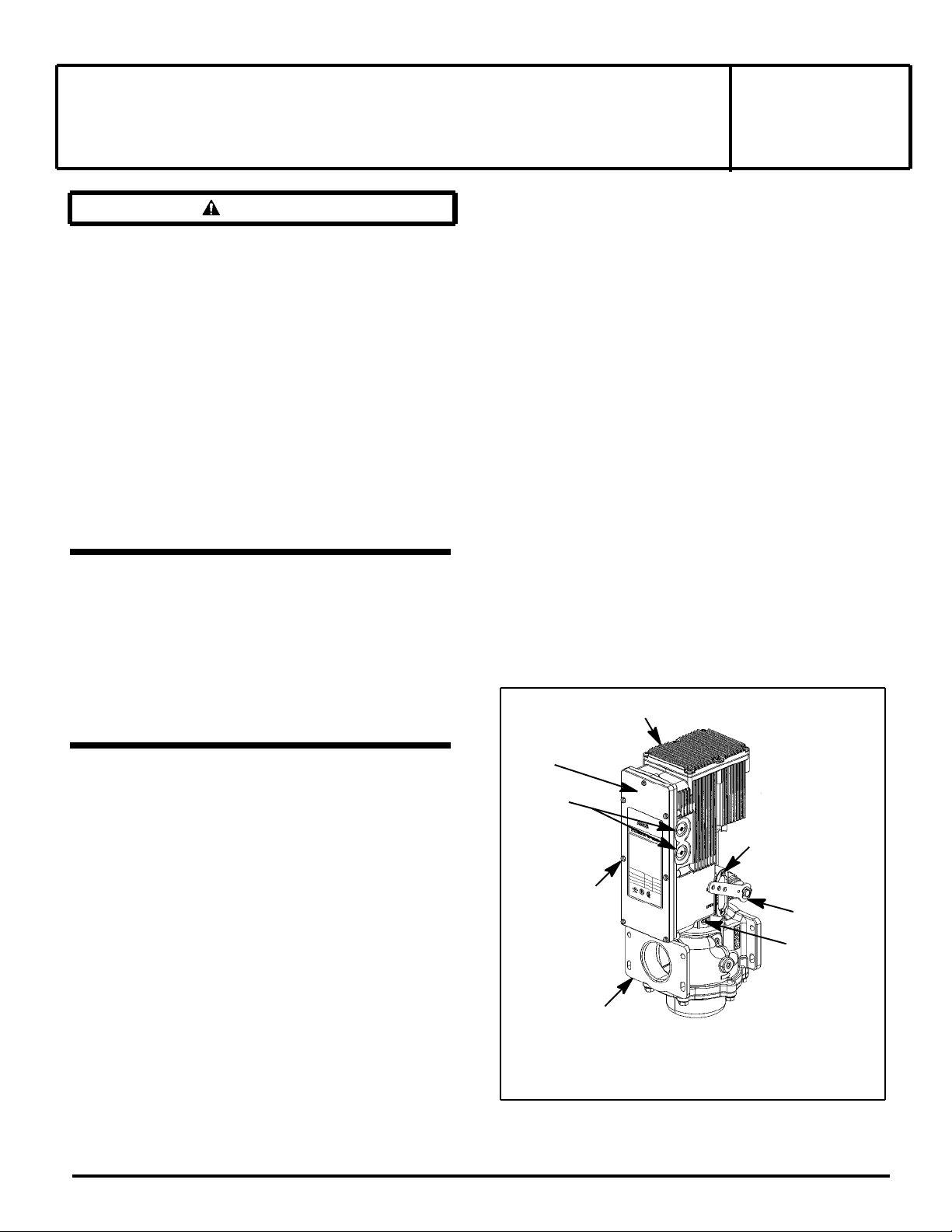
AH2E actuator assembly
Nameplate/electrical
cover
Conduit
knockouts
Cover screw
Valve assembly
AH2E Actuator and V710 Valve Assembly
Figure 1
SERIES
AH2E
Valve stem position indicator
Damper arm
(optional)
Mounting set screw
ASCO Valves®
E226360 - 5/12
All Rights Reserved.
I&M No. V 8860 R2
©ASCO Valve, Inc.® 50 Hanover Road, Florham Park, New Jersey 07932 www.ascovalve.com
Page 2
Specifi cations
Force Output: 250 lbs
Stroke: 1 1/8” maximum
Electrical Characteristics:
Operating
Voltage /
Frequency
Current, in Amperes
Inrush Opening Holding
24/60 28 8.2 0.49
120/60* 5.6 2.1 0.09
240/60* 2.8 1.1 0.04
*Current increases by 20% for 50Hz operation.
Opening Time: Fast Opening: 6 to 14 seconds
Slow Opening: 14 to 26 seconds
Note:
• Opening time doubles below -30°F (-34°C).
• 50Hz operation increases opening time by 20%.
• Opening time is not fi eld adjustable.
Maximum Closing Time: One second
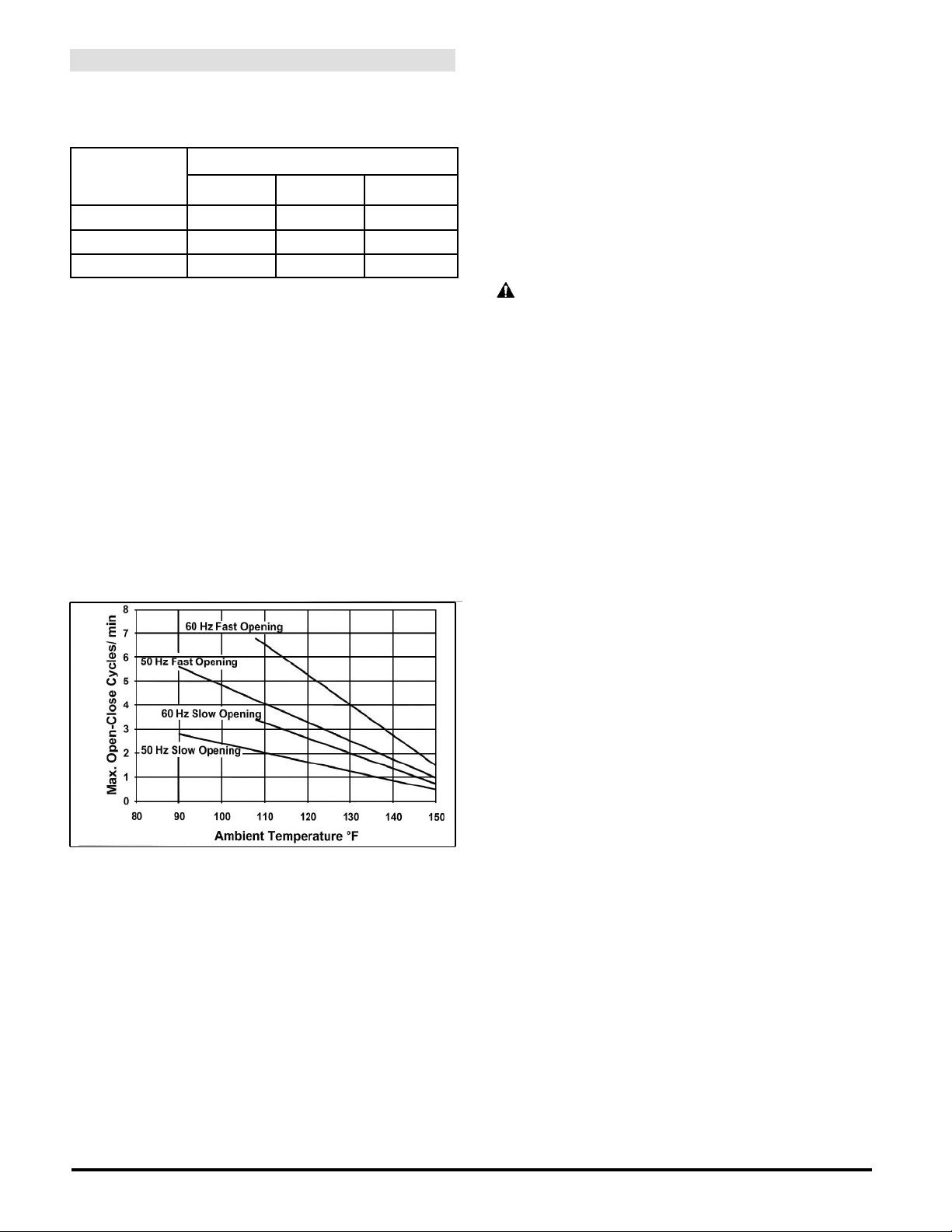
Ambient Temperature and Duty Cycle Limitations
The actuator may be operated in ambient temperature conditions
from -40°F to 150° F (-40°C to 65°C). Actuator can be cycled
open / close continuously below 108°F (42°C) for 60Hz and
below 90°F (32°C) for 50 Hz. See chart below for limitations
(open / close cycles) at elevated temperatures.
NOTICE
The AH2E actuator is fi tted with a self-resetting thermal cutout
device. If the recommended temperatures and duty cycles above
are exceeded, the thermal cutout may trip causing the actuator
to stop in its current position during valve opening. The valve
closing time remains one second or less regardless of thermal
cutout trip. Once the actuator cools,the cutout will self-reset and
the actuator will resume operation. If the cutout trips repeatedly,
verify that the application is within the ambient temperature and
the duty cycle limits of the actuator. If the application is within
the specifi ed operating limits and the cutout continues to trip,
replace actuator.
INSTALLATION
Positioning/Mounting
Follow the V710 Series Gas valve and/or damper manufacturer’s
instructions when installing the Hydramotor®.
1. AH2E actuators can be installed to operate in any position.
2. Check to ensure that the mounting gasket is in the proper
position, clean and without damage. Position the actuator
to operate the valve (and damper if appropriate). Secure
actuator with the three mounting set screws. Tighten set screws
to 80 ± 5 in-lbs [9,0 ± 0,5 Nm] using a 5/32” hex key wrench.
(See Figure 1)
Wiring (Refer to Figure 2)
WARNING: Electrical hazard. To prevent the
possibility of death, serious injury or property
damage, open all circuits before inspection, service
or disassembly.
Wiring must comply with local codes and the National Electrical
Code. Limit controls must conform with actuator rating (voltage,
amperage, hertz). Wiring to meet NEC Class I, suitable for 90°C.
Wire limit controls to the hot side of power supply.
1. Check the nameplate and confi rm that the appropriate power
is being supplied to the unit. Remove the front cover (with
nameplate) and set aside to access electrical connections taking
care not to damage the cover gasket if supplied. A diagram is
located on the inside of the cover to aid in making electrical
connections.
2. Remove the desired electrical knock out and install appropriate
electrical fi ttings. Type4 fi ttings must be used with watertight
units. Route wiring through the fi tting. Take care not to scratch
or otherwise damage the cover sealing surface when working
on watertight enclosure.
3. Connect the power to terminals 1 and 2. The neutral wire, if
applicable, should be connected to terminal 1. Connect the
ground wire to the grounding screw provided on the housing
next to the terminal strip.
4. Torque terminal screws: 8 to 12 in-lbs [0.9 to 1.3 Nm]. Torque
ground screw: 20 to 25 in-lbs (2.3 to 2.8 Nm)
5. If a proof of closure or auxiliary switch is being used make
those electrical connections. Use the markings located on
the insulators to determine normally open and normally
closed terminals. Torque electrical connection screws 8 to 12
in-lbs (0.9 to 1.3 Nm). Refer to auxiliary switch adjustment
section on page 3 for instructions on adjusting switch. Proof of
closure switches are set at the factory. Do not adjust proof of
closure switches.
6. Install the cover. Be certain that the gasket (if applicable)
and sealing surfaces are clean and there is no damage to the
surfaces or gasket. Snug down all screws before tightening.
Torque screws 20 to 25 in-lbs (2.3 to 2.8 Nm) evenly using a
crisscross pattern starting in the middle and not in the corner.
7. If the damper arm is being used, connect linkage and adjust as
needed for proper operation of the damper.
Damper Arm Adjustment: To reposition the damper arm,
remove the e-ring retainer and damper arm then reposition arm
and reinstall e-ring. When repositioning arm onto the opposite
side, remove e-rings on both sides and reposition and install
on opposite sides. DO NOT remove the square damper shaft.
8. Operate actuator (with valve) through fi ve cycles to verify
proper operation of valve and damper/ linkage system prior to
use.
Page 2 of 4
I&M No. V 8860 R2
©ASCO Valve, Inc.® 50 Hanover Road, Florham Park, New Jersey 07932 www.ascovalve.com
Page 3
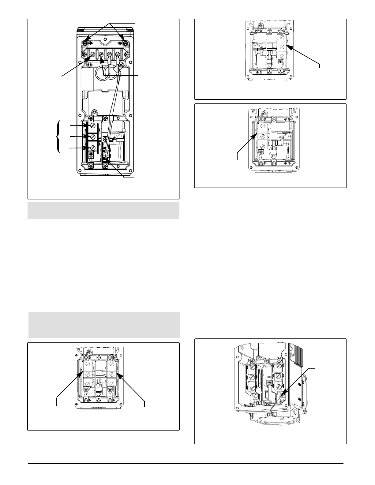
Ground screws
L1
N or L2
Connect neutral
to terminal 1 if
applicable
Proof of
closure
or
auxiliary
switch
NO
NC
C
Connect
to power
Travel limit switch
Do Not Adjust
Limit Switch Wiring
Figure 2
Auxiliary and Overtravel Proof-of-Closure
Switch Ratings
120VAC: 15 Amps, 1/3 HP
240VAC: 7.5 Amps, 1/2 HP
Total connected load of auxiliary and overtravel proof-of -closure
switches not to exceed 1800VA.
CAUTION: Overtravel Proof-of-closure switch must
only be used with V710 Series Gas Valves having an
overtravel seal (V22 or V25 Suffi x in catalog number).
Overtravel Proof-of-Closure Switch
The optional valve overtravel proof-of-closure switch is set at
the factory to provide both a mechanical and electrical means of
proving valve closed position interlock to the primary control.
This switch is not to be fi eld adjusted.
Optional
Auxiliary and Overtravel Proof-of-Closure
Switch Combinations (Partial Views)
Auxiliary
Single Auxiliary Switch
Figure 4
Proof-of-Closure
Proof-of-Closure Switch
Figure 5
Auxiliary Switch Adjustment (Refer to Figure 6)
Note: The Auxiliary switch is not a safety switch.
1. Before removing the cover, review WARNING
statements on page 1. Remove cover screws and
nameplate/electrical cover (with gasket if fi tted). Take
care not to damage the sealing surfaces and cover gasket if
supplied.
2. Insert 1/16” Allen key into adjusting screw on auxiliary
switch assembly.
3. Turn screw clockwise to move set point towards beginning
of actuator stroke. Turn screw counterclockwise to
move setpoint toward the end of the actuator stroke.
(approximately 8.5 turns from 0 to 100% travel)
4. Cycle the actuator to verify the switch setting and readjust
as required.
5. Install the cover. Be certain that the gasket (if applicable)
and sealing surfaces are clean and without damage. Snug
down all screws before tightening. Torque screws 20 to
25 in-lbs (2.3 to 2.8 Nm) evenly using a crisscross pattern
starting in the middle.
Aux. Left side Aux. Right side
Two Auxiliary Switches
Figure 3
Auxiliary Switch Adjustment
Figure 6
Page 3 of 4
I&M No. V 8860 R2
©ASCO Valve, Inc.® 50 Hanover Road, Florham Park, New Jersey 07932 www.ascovalve.com
Adjust
this
screw
Page 4
MAINTENANCE
Before inspection, maintenance or rebuild, review
WARNING statements on page 1. Maintenance should
include annual inspection and cleaning. Use a mild cleaning
fl uid, not aggressive solvents to remove dirt and oil. Organize
a maintenance schedule based on environment and frequency
of use. Check for loose electrical and mechanical connections
and replace damaged parts. Do not remove the top cover for
maintenance. There are no serviceable parts contained inside
the actuator housing.
Field Service Notice
Field service replacement kits are limited to the following:
1. Auxiliary Switch Replacement Kit 296804.
2. Proof of Closure Switch Replacement Kit 296806.
3. Travel Limit Switch Replacement Kit 296807.
4. Gasket and Screw Replacement Kit 296808.
Kit contains:
• Front cover gasket and screws
• Window o-ring and screws
• Mounting gasket and set screws.
To order, specify the kit or part number, as well as the actuator
model number.
Travel Limit Switch Replacement (Refer to Figure 8)
1. Before removing the cover, review WARNING
statements on page 1. Remove the front cover (with
nameplate) and set aside. Take care not to damage the
cover gasket if supplied or sealing surfaces. A diagram is
located on the inside of the cover to aid in making electrical
connections.
2. Remove the two mounting screws.
3. Disconnect wiring from the travel limit switch taking care
not to strain the wire connection at the terminal.
4. Install new travel limit switch. Torque mounting screws 20
to 25 in-lbs (2.3 to 2.8 Nm). Travel limit switches are set at
the factory. DO NOT adjust.
5. Plug terminal connections to travel limit switch.
6. Install the cover. Be certain that the gasket (if applicable)
and sealing surfaces are clean and without damage. Snug
down all screws before tightening. Torque screws 20 to
25 in-lbs (2.3 to 2.8 Nm) evenly using a crisscross pattern
starting at the middle.
7. Operate actuator (with valve) through fi ve cycles to verify
proper operation prior to use.
Auxiliary Switch Replacement (Refer to Figure 7)
Note: The Auxiliary switch is not a safety switch.
1. Before removing the cover, review WARNING
statements on page 1. Remove the front cover (with
nameplate) and set aside. Take care not to damage the
cover gasket if supplied or sealing surfaces. A diagram is
located on the inside of the cover to aid in making electrical
connections.
2. Disconnect auxiliary switch wiring.
3. Remove two mounting screws and the auxiliary switch.
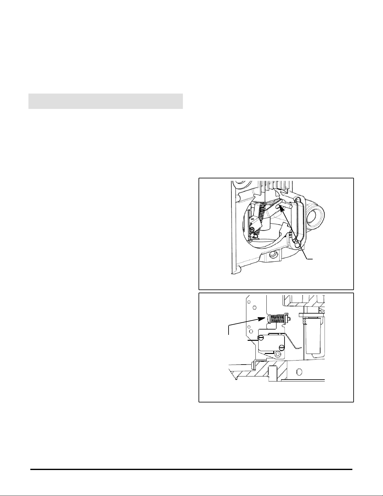
4. Install new auxiliary switch in the actuator making sure
that the fork of the switch actuation lever engages the
indicator arm as shown in Figure 8.
5. Torque mounting screws 20 to 25 in-lbs (2.3 to 2.8 Nm).
6. Reconnect switch wiring and torque terminal screws 8 to
12 in-lbs (0.9 to 1.3 Nm).
7. See instructions on page 3 for auxiliary switch adjustment,
starting at Step 2.
Proof of Closure Switch Replacement
Same as auxiliary switch replacement except switch must NOT
be adjusted.
Fork must
engage arm
as shown
Auxiliary Switch
Figure 7
Do not adjust
this screw
Limit Switch
Figure 8
Gasket replacement
The gaskets have an adhesive attachment. Use a nonmarring tool
to peel off the old gasket. Remove backing from new gasket and
stick on in the same location as the old gasket.
Page 4 of 4
I&M No. V 8860 R2
©ASCO Valve, Inc.® 50 Hanover Road, Florham Park, New Jersey 07932 www.ascovalve.com
 Loading...