

Asco 8215 Installation & Maintenance Instructions Manual
Installation & Maintenance Instructions
SERIES
2--WAY INTERNAL PILOT--OPERATED SOLENOID VALVES
NORMALLY CLOSED OPERATION -- 3/4I,1I,1--1/4I,1--1/2I OR 2I NPT
Positioning
IMPORTANT: See separate solenoid installation and
maintenance instructions for information on: Wiring,
Solenoid Temperature, Causes of Improper Operation, and
Coil Replacement.
DESCRIPTION
Series 8215 valves are 2--- way normally closed internal
pilot---operated solenoid valves. Valve bodies are made of
rugged aluminum with trim and internal parts made of steel
and sta inless steel. Series 8215 valves may be provided with
a general purpose or explosionproof solenoid enclosure.
OPERATION
Normally Closed: Valve is closed when solenoid is
de ---energized; open when energized.
Note: No minimum operating pressure differential
required.
INSTALLATION
CAUTION: Not all valves are approved for fuel gas
service. Check nameplate for correct catalog number,
pressure,voltage,frequency,andservice.Neverapply
incompatible fluids or exceed pressure rating of the valve.
Installation and valve maintenance to be performed by
qualified personnel.
Future Service Considerations
Provision should be made for performing seat leakage,
external leakage, and operational tests on the valve with a
nonhazardous, noncombustible fluid after disassembly and
reassembly.
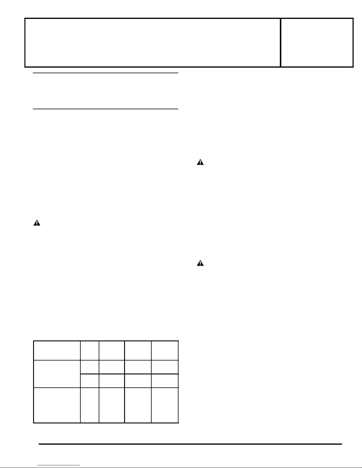
Temperature Limitations
For maximum valve ambient and fluid temperatures, refer
to chart below. Check catalog number prefix on nameplate
to determine maximum temperatures.
Valve must be mounted with solenoid vertical and upright.
Piping
Connect piping to valve according to markings on valve
body. Apply pipe compound sparingly to male pipe threads
only. Ifapplied to valvethreads the compoundmay enter the
valveandcauseoperationaldifficulty.Avoidpipestrainby
properly supporting and aligning piping. When tightening
thepipe,donotusevalveorsolenoidasalever.Locate
wrenches applied to valve body or piping as close as possible
to connection point.
CAUTION: To avoid damage to the valve body, DO NOT
OVERTIGHTEN PIPE CONNECTIONS. If Teflon* tape,
paste, spray or similar lubricant is used, use extra care when
tightening due to reduced friction.
IMPORTANT: To protect the solenoid valve, install a
strainer or filter, suitable forthe serviceinvolved, in the inlet
side as close to the valve as possible. Clean periodically
depending on service conditions. See ASCO Series 8600,
8601 and 8602 for strainers.
WARNING: T o prevent the possibility of
death, serious injury or property damage, turn off
electrical power, depressurize valve, extinguish all
open flames and avoid any type of sparking or
ignition. Vent hazardous or combustible fluid to a
safe area before servicing the valve.
NOTE: It is not necessary to remove the valve from the
pipeline for repairs.
8215
I&M No.V5996R6
MAINTENANCE
Catalog
Construction Coil
Class
AC Construction
DC Construction or or 77 77
ASCO Valves
EASCO Valve, Inc.R 50 Hanover Road, Florham Park, New Jersey 07932 www.ascovalve.com
Number
Prefix
F FT 125 125
H HT 140 140
B None
H HT
R
Max.
Ambient
Tem p _F
Max.
Fluid
Tem p _F
Cleaning
All solenoid valves should be cleaned periodically. The time
between cleanings will vary depending on the medium and
service conditions. In general, if the voltage to the coil is
correct, sluggish valve operation, excessive noise or leakage
will indicate that cleaning is required. In the extreme case,
faulty valve operation will occur and the valve may fail to
open or close. Clean valve strainer or filter when cleaning
the valve.
*Dupont Co. Registered Trademark
Page 1 of 4
E209037--- 04/ 10
All Rights Reserved.

Preventive Maintenance
S Keep the medium flowing through the valve as free from
dirt and foreig n m aterial as possible
Periodic exercise of the valve should be considered if
S
ambient or fluid conditions are such that corrosion,
elastomer degradation, fluid contamination build up, or
other conditions that could impede solenoid valve
shifting are possible. The actual frequency of exercise
necessary will depend on specificoperating conditions. A
successful operating history is the best indication of a
proper interval between exercise cycles.
S Depending on the me dium and service c onditio ns, periodic
inspection of internal valv e parts for damage or excessiv e
wear is rec omm ended. Thoroughly clean all parts. If parts
are worn or damaged, install a complete rebuild kit.
.
Causes of Improper Operation
S Incorrect Pressure: Check valve pressure. Pressure to
valve must be within range specified on nameplate.
S Excessive Leakage: Disassemble valve and clean all
parts. If parts are worn or damaged, install a complete
ASCO Rebuild Kit.
Valve Disassembly
WARNING: To prevent the possibility of
death, serious injury or property damage, turn off
electrical power, depressurize valve, extinguish all
open flames and avoid any type of sparking or
ignition. Vent hazardous or combustible fluid to a
safe area before servicing the valve.
NOTE: Determine valveconstructionAC (Figure1 onpage
3) or DC (Figure 2 on page 4) then proceed as follows:
1. Remove solenoid enclosure, see separate installation
and maintenance instructions.
2. For AC Construction, unscrew solenoid base
sub--- assembly. For DC Construction, unscrew solenoid
base sub---assembly with special wrench adapter
provided in ASCO Rebuild Kit. For wrench adapter
only, order kit No.K218---949. NOTE: For alternate
type open end wrench, order kit No.K168---146---1
which is available for solenoid base sub---assembly
removal or replacement.
3. Remove bonnet screws, valve bonnet, bonnet gasket,
core/diaphragm sub --- assembly and body gasket.
4. All parts are now accessible to clean or replace. If parts
are worn or damaged, install a complete ASCORebuild
kit.
Valve Reassembly
1. Lubricate bonnet gasket and body gasket with a light
coat of DOW CORNINGr 200 Fluid lubricant or an
equivalent high---grade silicone fluid.
2. ApplyalightcoatofTFL50r Dry Lube to:
S Va l ve se at
S Valve body flange where diaphragm assembly
contacts the valve body and body gasket.
S Internal surface of valve bonnet where
diaphragm assembly contacts bonnet when
valve is in the energized (open position).
IMPORTANT: If valve has been disassembled for inspection
and cleaning only and a Rebuild Kit is not being installed,
lubricate the following with TFL 50r Dry Lube:
S Diaphragm assembly on both sides.
S Main disc base of core/diaphragm sub- --assembly.
S Pilotdiscatbaseofcoreassembly.
CAUTION: Do not distort hanger spring between core
assembly and diaphragm assembly when lubricating pilot
disc.
3. Replace body gasket and cor e/ diaph rag m sub--- assembly
with closing spring attached. Locate bleed hole in
core/diaphragm sub---assembly approximately 30_ from
the val v e inlet.
4. Replace valve bonnet and bonnet screws (6). Torque
screws in a crisscross manner to 100 ±10 in --- lbs [11,3
±1,1Nm].
5. For AC construction, replace bonnet gasket and
solenoid base sub---assembly. Torque solenoid base
sub--- assembly to 45 ± 5 ft --- lbs [61,1 ± 6,8 Nm] For DC
construction refer to separate “Solenoid Installation
and Maintenance Instructions” for lubrication
instructions; then install bonnet gasket, housing and
solenoid base sub---assembly. Torque solenoid base
sub--- assembly to 30 ± 5 ft --- lbs [40,7 ± 6,8 Nm].
6. Replace solenoid (see separate instructions) and make
electrical hookup.
WARNING: To prevent the possibility of death,
serious injury or property damage, check valve for
proper operation before returning to service. Also
perfor m internal seat and exte r n al leakage tests
with a nonhazardous, noncombustible fluid.
7. Restore line pressure and electrical power supply to
valve.
8. After maintenance is completed, operate the valve a
few times to be sure of proper operation. A metallic
click signifies the solenoid is operating.
ORDERING INFORMATION
FOR ASCO REBUILD KITS
Parts marked with an asterisk (*) in the
exploded views are supplied in Rebuild Kits.
D When Ordering Rebuild Kits for ASCO Valves,
order the Rebuild Kit number stamped on the valve
nameplate.
+ If the number of the kit is not visible, order by
indicating the number of kits required, and the Catalog
Number and Serial Number of the valve(s) for which they
are intended.
Page 2 of 4
EASCO Valve, Inc.R 50 Hanover Road, Florham Park, New Jersey 07932 www.ascovalve.com
I&M No.V5996R6
 Loading...