

Page 1
Installation & Maintenance Instructions
2-WAY INTERNAL PILOTED-OPERATED SOLENOID VALVES
NORMALLY CLOSED OPERATION Ċ GENERAL SERVICE
3/8I, 1/2I OR 3/4I NPT
INSTALLATION
NOTICE: See separate solenoid installation and maintenance
instructions for information on: Wiring, Solenoid Temperature,
Cause of Improper Operation, Coil or Solenoid Replacement.
DESCRIPTION
Series 8210 valves are 2-way normally closed internal
pilot-operated solenoid valves designed for general service. Valves
are made of rugged forged brass. Series 8210 valves are provided
with a general purpose solenoid enclosure.
Series EF8210 and 8211 are the same as Series 8210 except they are
provided with an explosionproof or explosionproof/watertight
solenoid enclosure.
OPERATION
Normally Closed: Valve is closed when solenoid is de-energized;
open when energized.
IMPORTANT: Minimum operating pressure differential required
is 5 psi.
Manual Operator (optional feature)
Manual operator allows manual operation when desired or during an
electrical power outage. To engage manual operator (open the valve),
push in knurled cap and rotate stem clockwise 180_. Valve will now
be in the same position as when the solenoid is energized. To
disengage manual operator (close the valve), turn stem
counterclockwise 180_.
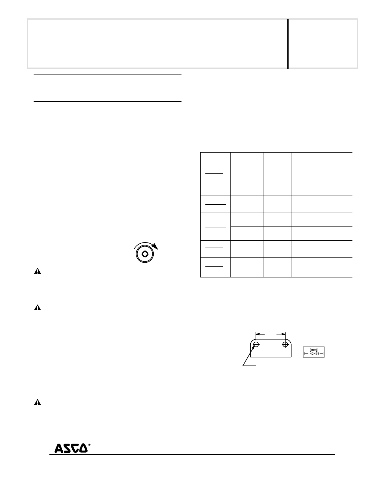
Push in and rotate
180°clockwise to operate
CAUTION: For valve to operate electrically, manual
operator stem must be fully rotated counterclockwise.
Relocation of Manual Operator
Manual operator may be relocated at 90_ increments by rotating the
valve bonnet as follows:
WARNING: To prevent the possibility of death,
serious injury or property damage, turn off electrical
power, depressurize valve, and vent fluid to a safe area
before relocating manual operator.
1. See separate solenoid installation and maintenance instruction's
and follow instructions to loosen solenoid to allow rotation of
enclosure.
2. Be sure manual operator stem is fully rotated counterclockwise.
3. Remove bonnet screws from valve body.
4. Lift valve bonnet slightly and rotate to desired position. Do not
rotate the diaphragm assembly with the valve bonnet.
5. Replace bonnet screws and torque in a crisscross manner to
95 ± 10 in-lbs [10,7 ± 1,1 Nm].
6. Position and tighten solenoid in place, see separate instructions.
WARNING: To prevent the possibility of death,
serious injury or property damage, check valve for
proper operation before returning to service.
7. Test operate valve electrically and manually. Be sure valve can be
test operated without effecting other equipment.
8. Restore line pressure and electrical power supply to valve.
e
MM All Rights Reserved.
Check nameplate for correct catalog number, pressure, voltage,
frequency, and service. Never apply incompatible fluids or exceed
pressure rating of the valve. Installation and valve maintenance to be
performed by qualified personnel.
Future Service Considerations
Provision should be made for performing seat leakage, external
leakage, and operational tests on the valve with a nonhazardous,
noncombustible fluid after disassembly and reassembly.
Temperature Limitations
For maximum valve ambient and fluid temperatures, refer to chart
below. Check catalog number and watt rating on nameplate.
Watt
Rating
AC
or
DC
6
AC
6.1
AC
11.2
DC
11.6
DC
Catalog
Number
Prefix
None or DF F 122 180
HT H 140 180
None, KF,
SF, or SC
HT, KH, ST
or SU
None or HT F or H 77 150
None, HT,
KF, KH, SC,
SF or ST
Solenoid
Class
F or H 104 150
Positioning
This valve is designed to perform properly when mounted in any
position. However, for optimum life and performance, the solenoid
should be mounted vertically and upright to reduce the possibility of
foreign matter accumulating in the solenoid base sub-assembly area.
Mounting
For mounting bracket (optional feature) dimensions, refer to Figure 1.
[42]
1.66
[ 7.1]
Ø
.28 dia.
2 mounting holes
Figure 1. Mounting bracket dimensions
Piping
Connect piping to valve according to markings on valve body. Apply
pipe compound sparingly to male pipe threads only. If applied to
valve threads, the compound may enter the valve and cause
operational difficulty. Avoid pipe strain by properly supporting and
aligning piping. When tightening the pipe, do not use valve or
solenoid as a lever. Locate wrenches applied to valve body or piping
as close as possible to connection point.
Printed in U.S.A.
SERIES
8210
8211
Form No.V5848R2
Max.
Amb.
Temp. _F
F 125 180
H 140 180
Page 1 of 4
Max.
Fluid
Temp. _F
50 Hanover Road, Florham Park, New Jersey 07932 www.ascovalve.com
Page 2

CAUTION: To protect the solenoid valve, install a strainer
or filter suitable for the service involved in the inlet side as
close to the valve as possible. Clean periodically depending
on service conditions. See ASCO Series 8600, 8601 and 8602
for strainers.
MAINTENANCE
WARNING: To prevent the possibility of death,
serious injury or property damage, turn off electrical
power, depressurize valve, and vent fluid to a safe area
before servicing the valve.
NOTE: It is not necessary to remove the valve from the pipeline for
repairs.
Cleaning
All solenoid valves should be cleaned periodically. The time between
cleanings will vary depending on the medium and service conditions.
In general, if the voltage to the coil is correct, sluggish valve operation,
excessive noise or leakage will indicate that cleaning is required. In
the extreme case, faulty valve operation will occur and the valve may
fail to open or close. Clean strainer or filter when cleaning the valve.
Preventive Maintenance
S Keep the medium flowing through the valve as free from dirt and
foreign material as possible.
S While in service, the valve should be operated at least once a
month to insure proper opening and closing.
S Depending on the medium and service conditions, periodic
inspection of internal valve parts for damage or excessive wear is
recommended. Thoroughly clean all parts. If parts are worn or
damaged, install a complete ASCO Rebuild Kit.
Causes of Improper Operation
S Incorrect Pressure: Check valve pressure. Pressure to valve must
be within range specified on nameplate.
S Excessive Leakage: Disassemble valve and clean all parts. If parts
are worn or damaged, install a complete ASCO Rebuild Kit.
Valve Disassembly
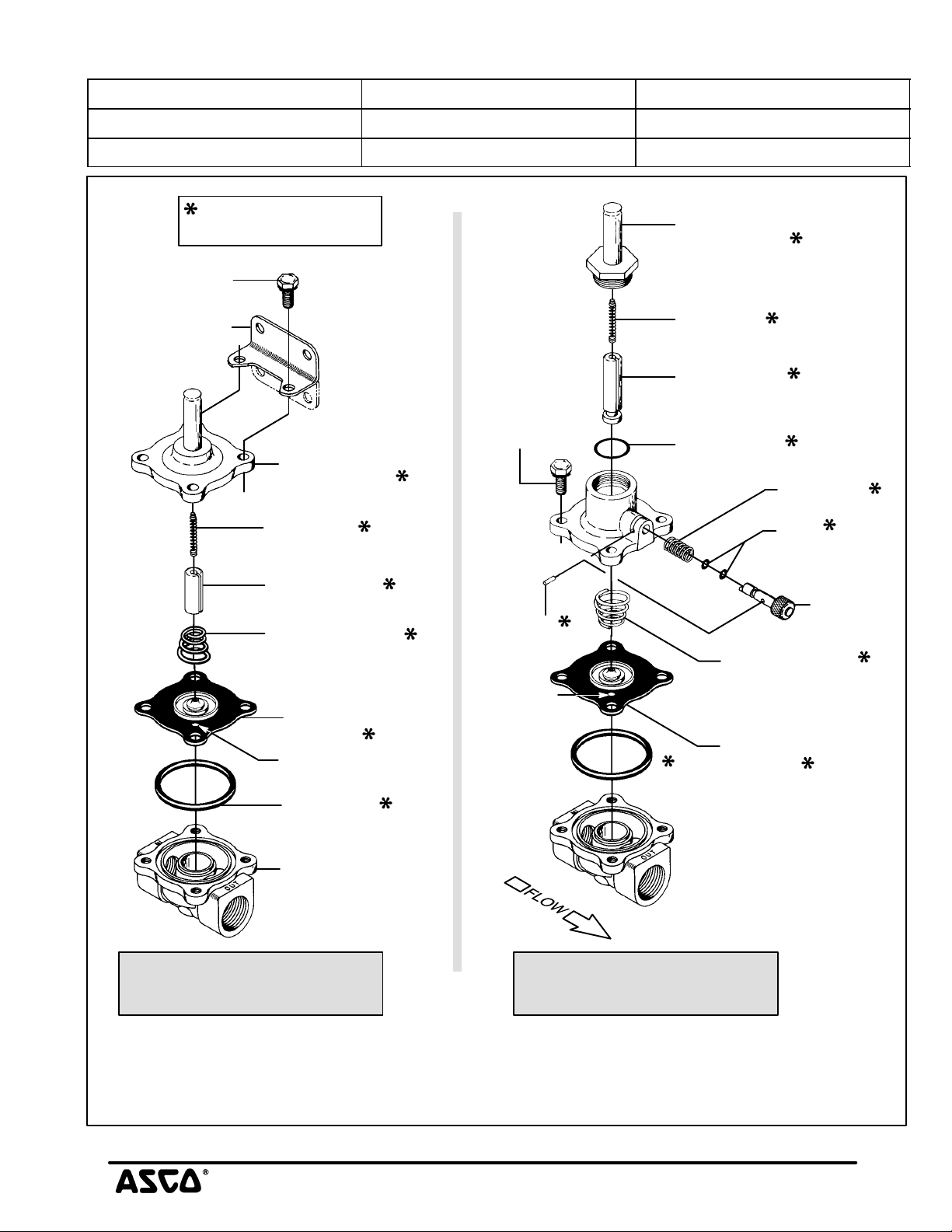
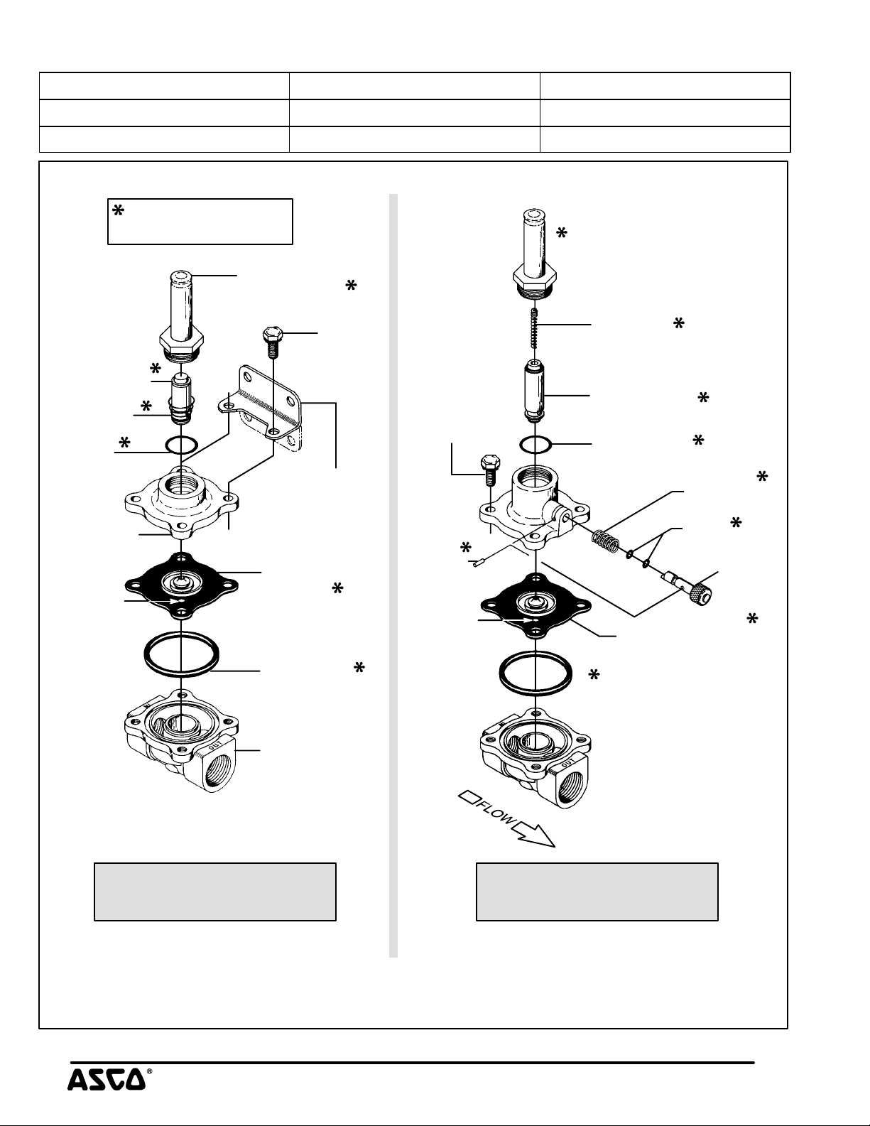
1. Disassemble valve in an orderly fashion using exploded views
for identification and placement of parts. Refer to Figure 2 for
AC construction; Figure 3 for DC construction.
2. Remove solenoid enclosure. See separate instructions.
S For AC construction (standard or with manual operator), proceed as
follows:
3. For standard construction, remove bonnet screws, solenoid
base sub-assembly, core spring, core assembly, diaphragm
spring, diaphragm assembly and body gasket from valve body.
4. For manual operator constructions, unscrew solenoid base
sub-assembly first then follow step 3 for removal of parts.
5. For normal maintenance (cleaning) it is not necessary to
disassemble the manual operator unless an ASCO Rebuild Kit
is being installed. To disassemble, remove stem pin, manual
operator stem, stem spring and stem gaskets (2).
S For DC construction (standard or with manual operator), proceed as
follows:
6. Unscrew solenoid base sub-assembly first then follow step 3
and 5 for removal of parts.
Note: Diaphragm spring is omitted for DC construction.
7. All Parts are now accessible for cleaning or replacement
parts are worn or damaged, install a complete ASCO Rebuild
Kit.
. If
Valve Reassembly
1. Lubricate body gasket and solenoid base gasket with DOW
CORNINGr 200 Fluid lubricant or an equivalent high-grade
silicone fluid.
2. Lubricate manual operator stem gaskets (2) with DOW
CORNINGr 111 Compound lubricant or an equivalent
high-grade silicone grease.
3. Replace body gasket and diaphragm assembly. Locate bleed
hole in diaphragm assembly approximately 45_ from valve
outlet.
S For AC construction (standard or with manual operator), proceed as
follows:
4. Position diaphragm spring on diaphragm assembly. Be sure
large end of diaphragm spring seats in cup of diaphragm
assembly. For manual operator constructions, small end of
diaphragm spring seats in cup of diaphragm assembly.
5. Install wide end of core spring in core assembly first, closed end
protrudes from top of core assembly.
6. For standard construction, position core assembly with core
spring and solenoid base sub-assembly (integral with bonnet)
over diaphragm spring and diaphragm assembly.
7. Install bonnet screws and hand thread screws as far as possible,
then torque bonnet screws in a crisscross manner to 95 ± 10
in-lbs [10,7 ± 1,1 Nm].
8. For valve constructions with a manual operator, first install
valve bonnet and bonnet screws as described in step 7.
9. Install solenoid base gasket, core assembly with core spring and
solenoid base sub-assembly.
10. Torque solenoid base sub-assembly to 175 ± 25 in-lbs
[19,8 ± 2,8 Nm].
11. For valves with a manual operator proceed as follows:
A. Install two manual operator stem gaskets on stem.
Refer to Step 2 for lubrication instructions.
B. Install stem spring and stem assembly with gaskets into
valve bonnet.
C. Push stem assembly into valve bonnet; align stem pin
hole and install stem pin.
D. Operate manual operator to be sure there is no
misalignment or binding. Then rotate manual operator
stem counterclockwise as far as possible.
S For DC construction (standard or with manual operator), proceed as
follows:
12. For standard or manual operator constructions, replace valve
bonnet and follow steps 7, 9 and 10. For manual operator
constructions, install core spring in core assembly following
step 5.
13. Install solenoid. See separate instructions.
WARNING: To prevent the possibility of death,
serious injury or property damage, check valve for
proper operation before returning to service. Also
perform internal seat and external leakage tests with
a nonhazardous, noncombustible fluid.
14. Restore line pressure and electrical power supply to valve.
15. After maintenance is completed, operate the valve a few times
to be sure of proper operation. A metallic click signifies the
solenoid is operating.
ORDERING INFORMATION
FOR ASCO REBUILD KITS
Parts marked with an asterisk (*) in the exploded view are supplied in
Rebuild Kits. When Ordering Rebuild Kits for ASCO valves, order
the Rebuild Kit number stamped on the valve nameplate. If the
number of the kit is not visible, order by indicating the number of kits
required, and the Catalog Number and Serial Number of the valve(s)
for which they are intended.
Page 2 of 4 Form No V5848R2
50 Hanover Road, Florham Park, New Jersey 07932 www.ascovalve.com
Page 3
Torque Chart
Part Name Torque Value Inch-Pounds Torque Value Newton-Meters
Solenoid base sub-assembly 175 ± 25 19,8 ± 2,8
Bonnet screws 95 ± 10 10,7 ± 1,1
Indicates Parts Supplied
In ASCO Rebuild Kits
bonnet screw (4)
mounting bracket
two positions
(optional)
solenoid base
sub-assembly
core spring
(see note 2)
core assembly
diaphragm spring
(large end of spring
to seat in cup of
diaphragm assembly)
diaphragm
assembly
bleed hole
(see note1)
bonnet
screw (4)
stem pin
bleed hole
(see note1)
solenoid base
sub-assembly
core spring
(see note 2)
core assembly
solenoid base
gasket
stem spring
stem
gaskets (2)
stem
diaphragm spring
(small end of spring
to seat in cup of
diaphragm assembly)
diaphragm
assembly
body gasket
valve body
AC Construction
Standard
Note:
1. Locate bleed hole in diaphragm assembly approximately 45_ from valve outlet.
AC Construction
with Manual Operator
2. Wide end of core spring in core first, closed end protrudes from top of core.
Figure 2. Series 8210 - AC construction without solenoid.
50 Hanover Road, Florham Park, New Jersey 07932 www.ascovalve.com
Page 3 of 4Form No.V5848R2
Page 4
Torque Chart
Part Name Torque Value Inch-Pounds Torque Value Newton-Meters
Solenoid base sub-assembly 175 ± 25 19,8 ± 2,8
Bonnet screws 95 ± 10 10,7 ± 1,1
Indicates Parts Supplied
In ASCO Rebuild Kits
solenoid base
sub-assembly
core assembly
core spring
solenoid
base
gasket
valve bonnet
bleed hole
(see note)
bonnet
screw (4)
mounting bracket
two positions
(optional)
diaphragm
assembly
body gasket
bonnet
screw (4)
stem pin
bleed hole
(see note)
core spring
( wide end in core first,
closed end protrudes
from top of core)
core assembly
solenoid base
gasket
stem spring
stem
gaskets (2)
stem
diaphragm assembly
valve body
DC Construction
Standard
Note:
Locate bleed hole in diaphragm assembly approximately 45° from valve outlet.
Figure 3. Series 8210 - DC construction without solenoid.
Page 4 of 4 Form No V5848R2
50 Hanover Road, Florham Park, New Jersey 07932 www.ascovalve.com
DC Construction
with Manual Operator
 Loading...