

Page 1
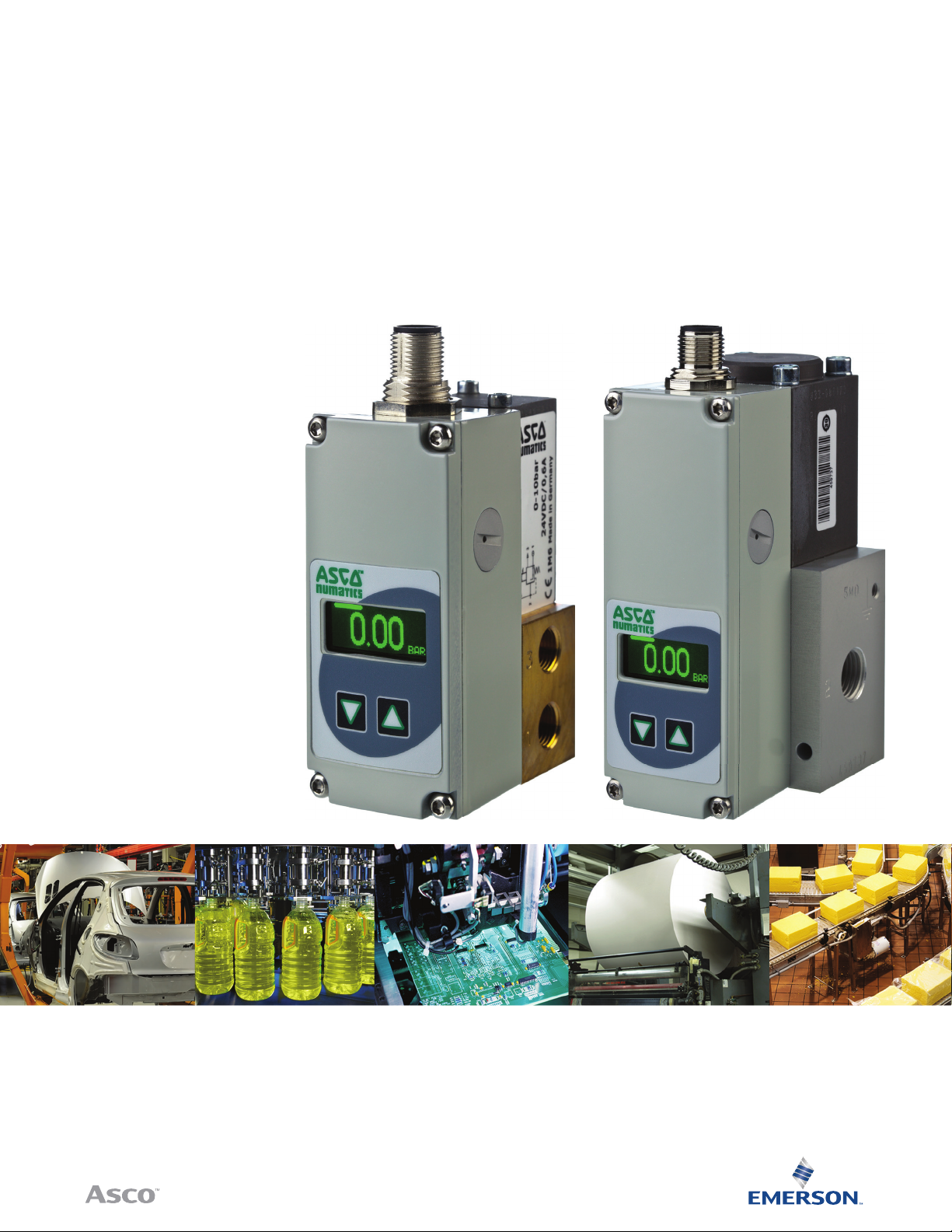
Sentronic
Electronic Pressure Regulator
Installation Manual
PLUS
IO-Link CLASS A
Page 2
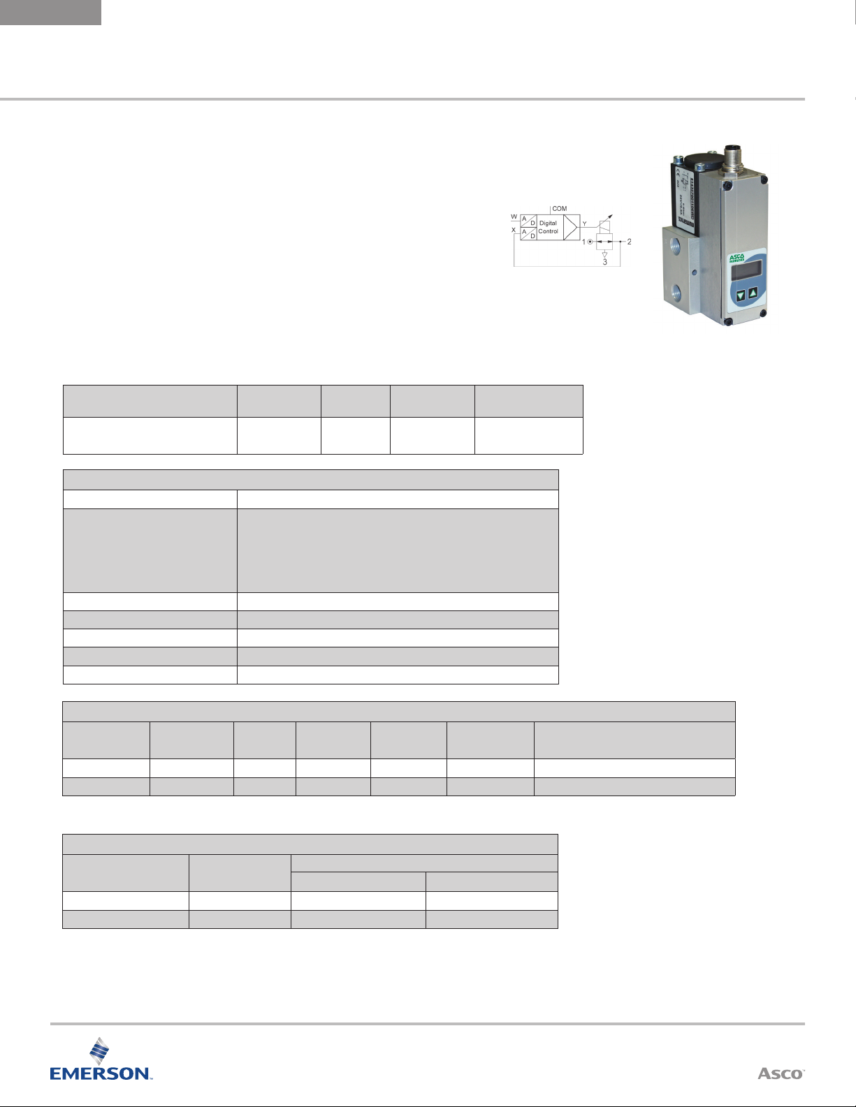
Sentronic
PLUS
INSTALLATION
MANUAL
ELECTRONIC
PRESSURE REGULATOR
ASCO NUMATICS™
Sentronic
Sentronic
•
Direct operated valve
•
Dynamic behavior (high speed)
•
IO - Link CLASS A Version
•
RoHS, REACH compliant
Air or neutral gas, ltered at 50 µm,
condensate-free, lubricated or
PLUS
Electronic Pressure Regulator
PLUS
is a 3-way proportional valve with digital control.
Fluids
unlubricated
Ambient
Temperature
0 °C to 60 °C
(32 ºF to 140 ºF)
Aluminum
General Valve Information
Fluid Temperature 0 ºC to 60 ºC (32 °F to 140 °F)
PSI Pressure Ranges:
PA & PB (50 & 100 psi ranges): in digital steps of 0.01 psi
PC (150 psi range): in digital steps of 0.1 psi
Command Signal- IO-Link
Ports 1/8, 1/4 (NPT or GTap)
Construction Direct-operated Poppet Valve
Hysteresis 0.5% of span
Linearity/ pressure measurement ± 0.5% of span
Repeatability ± 0.5% of span
Bar Pressure Ranges:
40, 50, 60, V1, V2 & V3 (100mbar, 500mbar, 1bar & all vacuum): in digital
steps of 0.00 01 bar
All others: in digital steps of 0.001 bar
Body
Internal
Parts
Stainless steel
and brass
Seals
NBR (nitrile) and
FPM ( uoroelastomer)
2
Electrical Characteristics
Nominal
Diameter DN
(mm)
3 24 VDC = ± 10% 12 500 F IP65 5-pin M12 connector or 7-pin DIN connector
6 24 VDC = ± 10% 24
* Max. ripple: 10%
1
For DN6, b rass version G o r H/1.8A, 44W
Volt age *
Max.
Power (W)
1
Max. Current
(mA)
1
1000
Insulation
Class
F IP65 5-pin M12 connector or 7-pin DIN connector
Degree of
Protection
Electrical Connection
Specifi cations
Ø
Ports
1/8 NPT or GTap 3 0.21 (0.18) 210
1/4 NPT or GTap 6 0.70 (0.60) 700
Ø
Orifi ce DN
(mm)
Cv Flow Fac tor (K
Visit our website at ASCO.com or contact us at (800) 972-2726
Flow
Nm3/h) at 6 Bar ( l/min - A NR)
v
Page 3
ASCO NUMATICS™
How to Order
6 1 4 3 5 7 E 9 0 1 1 PB
Control Panel
B = IO-LINK with display
C = IO-Link without display
ELECTRONIC
PRESSURE REGULATOR
Options
A00 = Dual loop control
018 = Oxygen clean
Sentronic
PLUS
INSTALLATION
MANUAL
Version
0 = DN6 (G 1/4), ALU
4 = DN6 (NPT 1/4), ALU
7 = DN3 (G 1/8), Brass
8 = DN6 (G 1/4), Brass
9 = DN3 (NPT 1/8), Brass
A = DN6 (NPT 1/4), Brass
C = DN6 (G 1/4), Stainless Steel
Command Signal
B = IO-LINK CLASS A
Feedback
B = IO-LINK CLASS A
(ports)
, Body
Pressure Range
Output Pressure
(psi)
40 = 0 – 0.1 bar (1.5)
50 = 0 – 0.5 bar (7.3)
60 = 0 – 1 bar (14.5)
02 = 0 – 2 bar (29)
03 = 0 – 3 bar (44)
PA = 0 – 3.4 bar (50)
05 = 0 – 5 bar (73)
06 = 0 – 6 bar (87)
PB = 0 – 6.9 bar (100)
10 = 0 – 10 bar (145)
PC = 0 – 10.3 bar (150)
12 = 0 – 12 bar (174)
Digital Output
1 = Standard
Max. Inlet
Pressure
(psi)
2 (29)
2 (29)
2 (29)
3 (44)
8 (116)
8 (116)
8 (116)
12 (174)
12 (174)
12 (174)
12 (174)
14 (203)
Vacuum
(relative)
V1 = 0 to -1 bar
Shut-off valve,
connects to
vacuum on loss
of power
V2 = 0 to -1 bar
Bypass valve
V3 = 0 to -1 bar
Shut-off valve,
connects to
atmosphere on
loss of power
Absolute Pressure
Ranges Available
on Request
Operating Modes
Shut-o:
If the setpoint falls below 0.5 %, the coil current is switched o and the valve is fully exhausted.
Overtemperature:
If the temperature of the internal control electronics exceeds 100°C, the operating mode is switched to AUTOSAFE.
Undervoltage / overvoltage:
If the supply voltage is less than 18 V or more than 30 V, the coil current is switched o and the valve is fully
exhausted.
Autosafe:
If the coil current exceeds a certain value, dependent on the mechanics, for more than 20 seconds, the output
current is limited to max. 70% to prevent the valve from overheating.
Visit our website at ASCO.com or contact us at (800) 972-2726
3
Page 4

Sentronic
0.98 (25)
1.14 (29)
1.38 (35)
3.75 (95.2)
3.17 (80.5)
1.02 (26)
0.39 (10)
0.71 (18)
0.98 (25)
2xM4-10 deep
3.75 (95.2)
PLUS
INSTALLATION
MANUAL
Dimensions: Inches (mm), Weight in lbs. (kg)
1/8 NPT or GTap (DN3)
Weight: 1.21 (0.55)
ELECTRONIC
PRESSURE REGULATOR
PE (4-8 deep)
ASCO NUMATICS™
1/4 NPT or GTap
Weight: 1.87 (0.85)
3.17 (80.5)
4.52 (114.7)
4.15 (105.3)
2.18 (55.3)
1.02 (26)
0.39 (10)
1.78 (45.3)
0.43 (11)
0.98 (25)
1.14 (29)
1.38 (35)
1.38 (35)
1.69 (43)
2.05 (52)
2 x M4-10 deep
0.98 (25)
0.71 (18)
1.18 (30)
0.39 (10)
3 x 1/8"-8 deep
0.59 (15)
0.98 (25)
2.68 (68)
2.24 (57)
1.42 (36)
PE(4-8 deep)
1.02 (26)
3x1/4"-12 deep
A) Thread M5 - depth 10
(on opposite side);
tapped through-hole
for M4 screw.
4
Visit our website at ASCO.com or contact us at (800) 972-2726
Page 5

ASCO NUMATICS™
ELECTRONIC
PRESSURE REGULATOR
Connector Pin Out
Pin Description
1
2
4
5
3
M12 Class A & B Compatible Cables* and Accessories
1 +24 VDC Supply
2 not connected
3 +0 VDC Common (Supply)
4 C/Q
5 not connected
Body EMC shield
M12 Straight 5 Pin Female Single Ended Cable - Unshielded
TC0505MIE000071P – 5 Meter
TC0 510M IE 000 071P – 10 Mete r
Sentronic
PLUS
INSTALLATION
MANUAL
M12 Straight 5 Pin Female to Male Double Ended Cable - Unshielded
TC0505MIETA0571P – 5 Meter
TC0 510M IE TA0571P – 10 Mete r
M12 90° 5 Pin Female Single Ended Cable - Unshielded
TD0505MIE000071P – 5 Meter
TD 0510MIE0 00 071P – 10 Mete r
M12 90° 5 Pin Female to Male Double Ended Cable - Unshielded
TD0505MIETA0571P – 5 Meter
TD 0510MIETA0571P – 10 Meter
*Reference our G3 Fieldbus catalog for M12 4 pin cables if the selected IO-Link® Master does not
accept 5 pin cables. Maximum IO -Link c able length is 20 m.
Visit our website at ASCO.com or contact us at (800) 972-2726
5
Page 6

Sentronic
INSTALLATION
MANUAL
PLUS
ELECTRONIC
PRESSURE REGULATOR
ASCO NUMATICS™
Installation and Operating Instructions
1. Before putting into operation carefully check all electrical connections and the supply voltage (24 VDC ±10 %).
Overload can destroy the electronics. Recommended pre-fuse T2.0 A.
2. The electrical connection is made with a round connector M12x1. The connector must meet the requirements of
DIN 60079-15.
WARNING:
Do not disconnect the plug while under voltage!
When disconnected from power, use supplied protection cover to ensure IP protection.
3. Use unshielded or shielded cables for the electrical connection of the valve. The shield, connector and control
cabinet must be EMC compliant. The valve body must be electrically connected to ground (PE, machine ground).
Do not run control cables parallel to high-voltage lines or servo-motor control cables.
4. The cable length between the IO-Link master and the valve must not exceed 20m.
5. Make sure that the valve is under pressure when a setpoint signal is applied to the valve (applying a setpoint
signal with no pressure on the valve will cause it to overheat).
6. The valve is factory adjusted.
7. The product must be returned to the factory for repair.
Warning
These products are intended for use in industrial compressed air systems only. Do not use these products where
pressures and temperatures can exceed those listed under SPECIFICATIONS.
Before using these products with uids other than those specied, for non-industrial applications, life-support systems,
or other applications not within published specications, consult ASCO Numatics.
Through misuse, age, or malfunction, components used in uid power systems can fail in various modes.
The system designer is warned to consider the failure modes of all component parts used in uid power
systems and to provide adequate safeguards to prevent personal injury or damage to equipment in the
event of such failure.
System designers must provide a warning to end users in the operating manual if protection against a failure mode
cannot be adequately ensured.
System designers and end users are cautioned to review specic warnings found in instruction sheets packed and
shipped with these products.
6
Visit our website at ASCO.com or contact us at (800) 972-2726
Page 7

Global Contacts
Australia
(61) 2-9-4 51-7077
Brazil
(55) 11-4208-1700
Canada
(1) 519-758-2700
China
(86) 21-3395-0000
Czech Republic
Dubai - UAE
(420) 235-090-061
(971) 4-811-8200
ASCO (USA) | Tel (1) 888-686-2842 | an.insidesales@emerson.com | www.ASCO.com
France
(33) 2-37-24-42-24
Germany
India
Italy
Japan
Mexico
(49) 7237-9960
(91) 44-3919730 0
(39) 02-356931
(81) 798-65-6361
(52) 55-5809-5640
Netherlands
Singapore
South Korea
Spain
United Kingdom
(31) 33-277-7911
(65) 6556-1100
(82) 2-3483-1570
(34) 942-87-6100
(44) 1695-7136 00
4/19
 Loading...