

Page 1
5101 Engine Start Monitoring System
TABLE OF CONTENTS
Page
GENERAL INFORMATION
Overview .................................................................................................................................................................................................... 3
Main Specifications ................................................................................................................................................................................... 3
Dimensions 5101-GEN Reference Drawing, 5101-ATS Reference Drawing .............................................................................................. 4
SYSTEM ARCHITECTURE
SYSTEM COMPONENTS/REQUIREMENTS
Generator Module (5101-GEN) Requirements ........................................................................................................................................... 6
Transfer Switch Module (5101ATS) Requirements .................................................................................................................................... 6
DESCRIPTION OF OPERATIONS
Testing........................................................................................................................................................................................................ 8
LED Status ................................................................................................................................................................................................. 8
CONFIGURATION and INSTALLATION
Steps of Installation .............................................................................................................................................................................. 9-11
SETTINGS
5101-GEN Module: DIP Switches ............................................................................................................................................................ 12
..........................................................................................................................................................................................
START-UP CHECKLIST
CALIFORNIA PROPOSITION 65 WARNING
INDEX
................................................................................................................................................................................................... 16
..........................................................................................................................................................
.............................................................................................................................................................. 5
............................................................................................................................
...........................................................................................................................................
....................................................................................................................................
3-4
6
7-8
9
12
................................................................................................................................................................ 13
......................................................................................................................... 14
Florham Park, NJ 07932-1591
Call 1 800 800-2726 (ASCO) for sales or service
381333-474 C
Page 2

5101 Engine Start Monitoring System
This page left blank intentionally.
2 381333-474 C
Page 3

5101 Engine Start Monitoring System
General Information
Overview
A susceptible location for a control wiring fault is in the long distance wire run between a transfer switch’s locations to
the generator’s location. This wire run could travel through hundreds of feet of conduit in any part of a facility where
damage due to construction or other factors could go unnoticed for extended periods. This could result in generators
failing to start when called upon by transfer switches during outage conditions.
The ASCO 5101 Engine Start Monitoring System (5101-ATS/5101-GEN) is a system designed to forward engine start
signals while continuously monitoring for wiring faults according to the electrical code NEC 700.10. Typically, the
transfer switch control circuits use a relay contact to signal the generator to start. The transfer switch engine start contact
is connected to the generator using two wires. The generator and transfer switch may be close together or may be a long
distance apart. In some cases, a single transfer switch is used with a generator, but in other cases multiple transfer
switches may need to start the same generator.
During proper operation, the generator controls detect the relay state and determine if the generator should be started.
Depending on the system, the contact may either open or close to signal a start condition. The engine start relay has only
two states: open or closed. In the event that a fault occurs in the signal wiring, the generator start function may not
function properly.
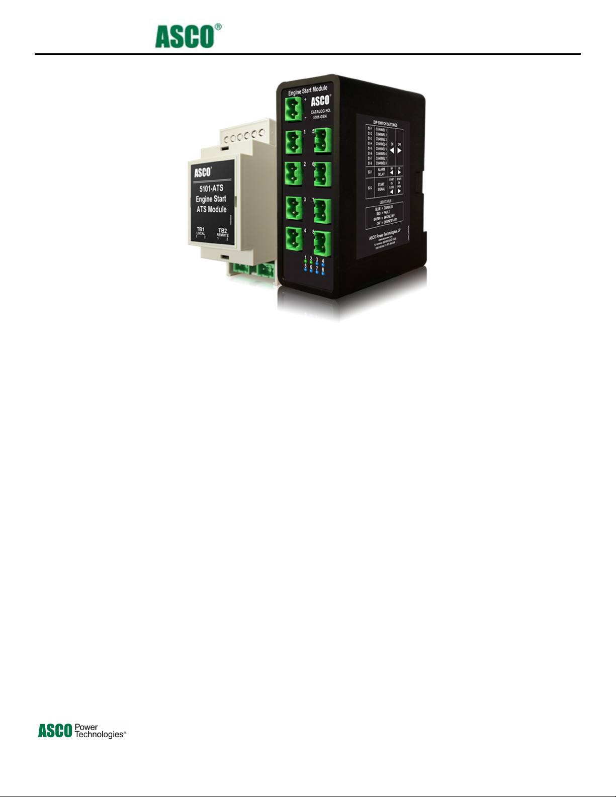
The 5101 Engine Start Monitoring System uses two modules: (5101-ATS and 5101-GEN) one at each transfer switch and
one at the generator. The generator module receives the engine start signal from each ATS module (up to 8 modules) and
monitors for any faults in the wiring. If the 5101-GEN receives any engine start signal or if it detects any faults, it will
send the start signal to the generator and provide an alarm.
When used with switchgear or power control systems, the 5101 Engine Start Monitoring System should only be applied to
the wiring between the transfer switches and gear. The 5101 solution should not be applied between the power control
system and generator due to the fact that this is considered part of the generator control wiring and requires many more
critical signals to properly operate the generator beyond the traditional two wire engine start (ex. synchronization, breaker
control and cranking control signals, etc.).
Main Specifications
Parameter Description
DC Power
Internal Ride Through Power 3 seconds minimum
Mounting 35mm DIN rail
Operating Temperature Range
Maximum Distance 1000 feet one way from ATS to GEN (2000 feet loop)*
Maximum Wire Loop Resistance Resistance must be less than 100Ω ohms
Generator Module Start Contact 1A 30VDC (Form C)
Generator Module Alarm Contact 1A 30VDC (Form C)
Wire Gauge 12-30 AWG stranded
*Contact ASCO Power Technologies for longer distances.
9-27V 15W max (Gen- Module) / ATS module does not
require power
-20℃ to 70℃
381333-474 C 3
Page 4
5101 Engine Start Monitoring System
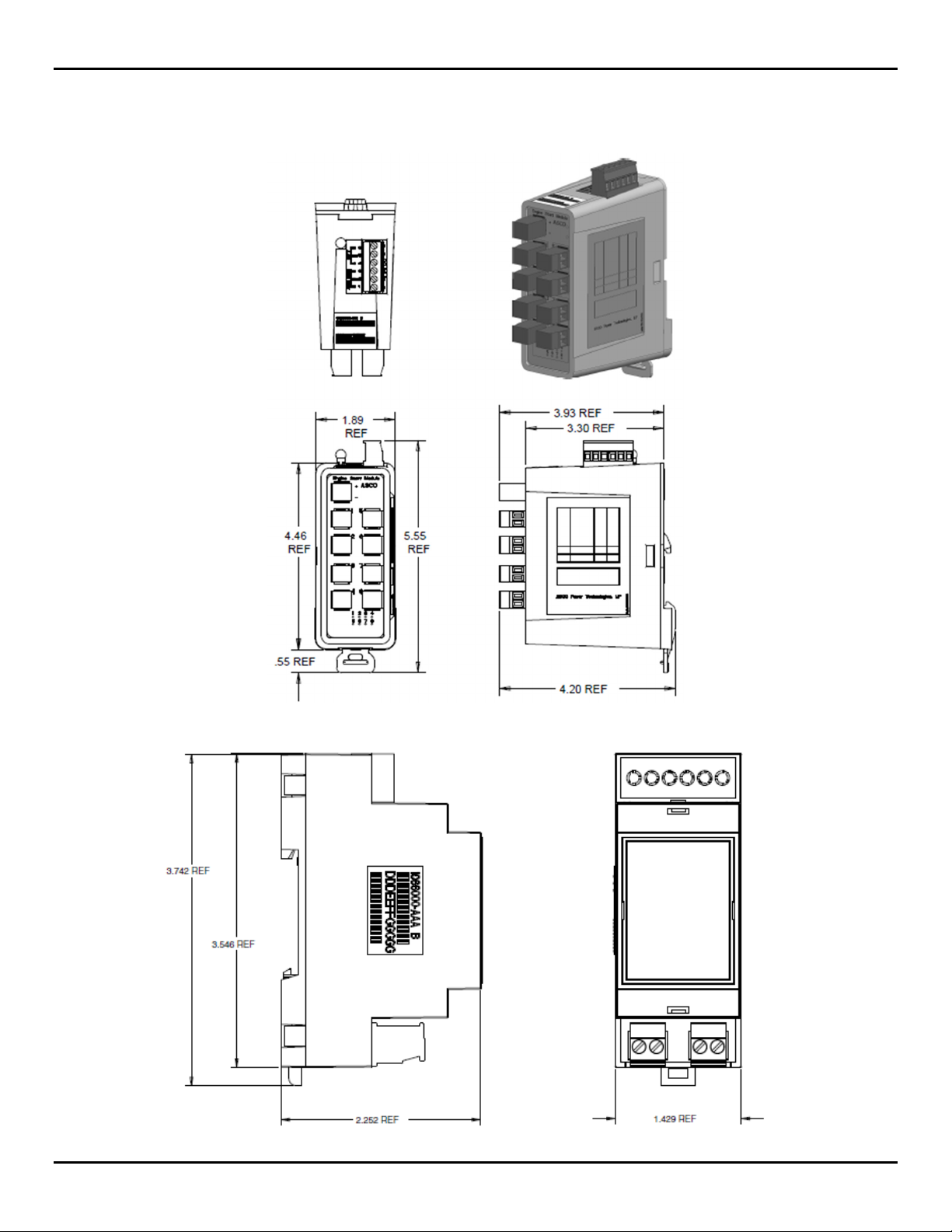
Dimensions
5101-GEN Module Reference Drawing
5101-ATS Module Reference Drawing
4
381333-474 C
Page 5
5101 Engine Start Monitoring System
System Architecture
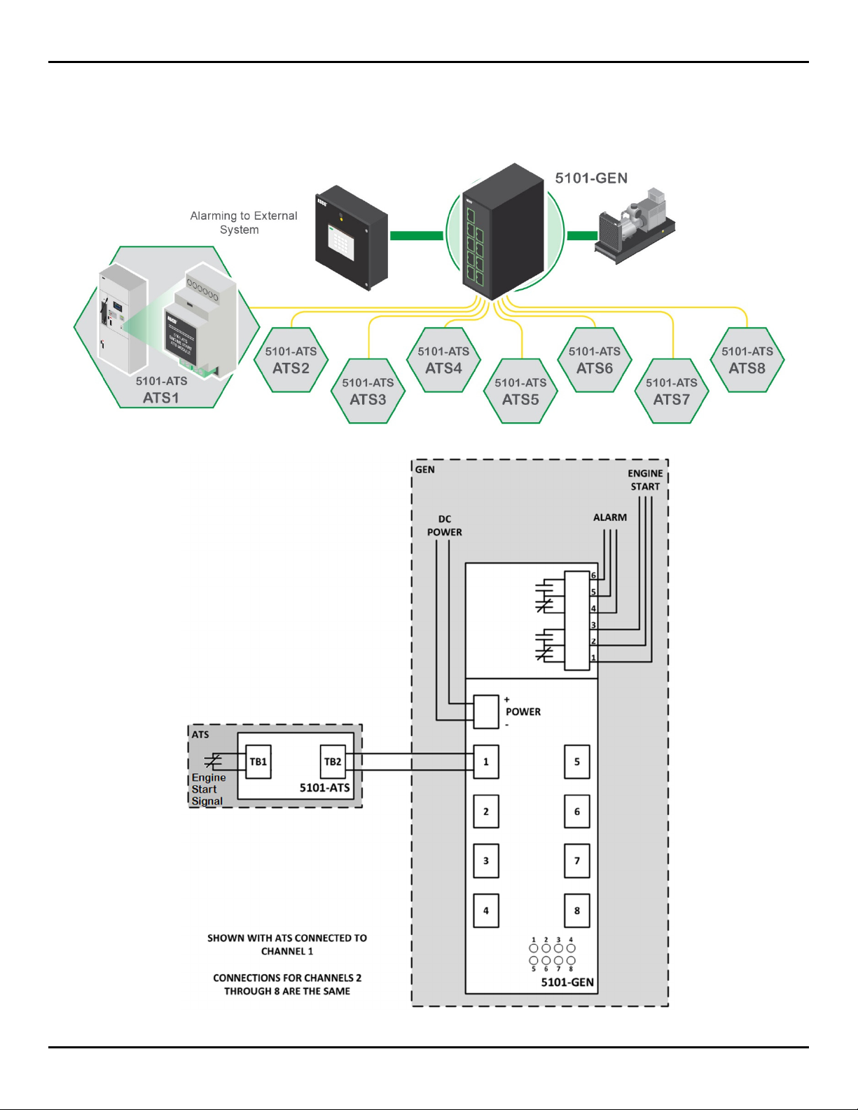
Figure 1 shows the overall structure of the 5101 Engine Start Monitoring System, while Figure 2 shows a simplified
version of the installation.
Figure 1. System Block Diagram
Figure 2. Installation Diagram
381333-474 C
5
Page 6

5101 Engine Start Monitoring System
System Components/Requirements
Generator Module (5101-GEN)
o Inputs
Requires power from 24Vdc (usually from generator battery)
Receives up to 8 individual signals from ATS modules (5101-ATS)
o Outputs
Sends engine start signal to the generator via form C output.
Provides alarm signal (form C) in case of fault.
Transfer Switch Module (5101-ATS)
o Inputs
TB1 is connected to the engine start signal relay of the transfer switch controls.
o Outputs
TB2 is connected to a generator module (5101-GEN)
Generator Module (5101-GEN) Requirements
The Generator module (5101-GEN) must be properly wired to the generator and transfer switch module (5101-ATS) for it
to operate correctly. The generator module requires 24Vdc control power. The module should be fed from the DC voltage
available at the generator.
Prior to operation, the DIP switches on the rear of the module must be configured for the applications. I.e. if the
application only requires 5 transfer switches, the other 3 available channels in the module should be disabled. By
disabling the unused channels, it prevents false alarms from starting the generator. Based on the system, the unit can be
used in 2 modes: START ON OPEN or START ON CLOSE. The user must determine which mode to use and program
the module accordingly using the S2-2 DIP switch. (See Settings for more information.)
The total length of connection wire between the generator module and the transfer switch module shall not exceed 1000 ft.
or 100 Ohms. The module is DIN rail mountable and should be used with standard 35mm DIN rail.
Transfer Switch Module (5101-ATS) Requirements
The Transfer Switch Module (5101-ATS) does not require any power to operate. The module must have its two terminal
blocks (TB1 and TB2) wired correctly. TB1 must be connected to the engine start signal relay of the transfer switch
controls. The TB2 should have 2 wires going to the generator module.
Like the generator module, the 5101-ATS is DIN rail mountable and should be used with standard 35mm DIN rail.
6 381333-474 C
Page 7

5101 Engine Start Monitoring System
Description of Operations
The 5101 operates using two modules in addition to the traditional engine start contact on a transfer switch and the engine
start input at a generator. The first module is the 5101-ATS module which resides near to or within an ATS. The second
module is the 5101-GEN module which resides within or near to the generator enclosure. Using these modules allows the
system to monitor the integrity of the control wiring between the two modules. Since these modules are extremely close to
their terminal points and the long distance run between them is monitored for faults (short or open circuit) they greatly
increase the reliability of the system by minimizing the chances that such a fault goes un-noticed.
The system uses a 5101-ATS module placed inside the transfer switch and requires no power. This module connects to the
traditional engine start contact (open or close to start) locally within the transfer switch. This module’s output (TB2) is
then wired to the 5101-GEN module.
The 5101-GEN module requires 24Vdc control power from a reliable source (usually generator batteries) to properly
operate. It can accept connections from up to 8 5101-ATS modules. The 5101-GEN module’s outputs are one Form C
output contact used to feed the generator’s start input as well as one Form C Alarm contact to feed any external
monitoring system.
These two modules work in collaboration to sense the state of the source contact feeding the 5101-ATS module and
mimicking its position at the 5101-GEN module. This allows the system to properly start and stop the generator during
normal operation with intact wiring, however should the two modules detect a short or open fault between themselves
they shall enter alarm mode by dropping out the alarm contact and generator contact. This ensures that the generator is
available should a transfer switch require it while also bringing attention to the fault so that it can be corrected.
381333-474 C 7
Page 8

5101 Engine Start Monitoring System
Testing
To verify that the 5101 system is working correctly, simulate a fault condition and observe the LEDs change colors (See
LED Description section). To simulate a fault condition for a channel, either remove the channel’s terminal block from
the front of the generator module, or place a jumper across the channel terminal block. In both cases, the channel’s LED
should change to RED and the alarm relay should deenergize.
LED Status Description
LEDs on the front of the generator module provide status for each channel. The color of the LED indicates the status of
the channel.
Color Status Description Start Output State Alarm Output State
Blue Channel is disabled N/A N/A
Red Wiring fault detected De-energized De-energized
Green Engine start is not active – wiring is OK Energized Energized
Off Engine start is active – wiring is OK De-energized Energized
8 381333-474 C
Page 9

5101 Engine Start Monitoring System
Configuration and Installation
Steps of Installation:
1. Wire ATS Module to Automatic Transfer Switch engine start signal via TB1.
381333-474 C
9
Page 10

5101 Engine Start Monitoring System
2. Wire ATS Module to Generator Module (5101 Gen) via TB2.
3. Repeat steps 1 and 2 for all ATS Modules used.
4. Confirm and adjust DIP switches as necessary (See Settings for more information).
10 381333-474 C
Page 11

5. Wire 5101-GEN to 24Vdc power
5101 Engine Start Monitoring System
6. Wire desired engine start signal to Generator. NO side of contact will open to signal generator start and NC side of
contact will close to signal generator start.
7. Wire Alarm signal output to other module/system.
381333-474 C 11
Page 12

5101 Engine Start Monitoring System
Settings
5101- Gen Module: DIP Switches
The module contains DIP switches in the back which allow the customer to configure the system.
The switches S1-1:8
correspond to channels 1-8
respectively. Toggling left
will enable the channel
while toggling right will
disable it
The S2-1 switch
corresponds to the alarm
delay. Toggling left will
turn it off
(instantaneous, no delay)
and toggling right will
turn it on (3 sec delay).
The S2-2 switch is the
reference for the start
signals wired into the
5101-ATS modules. This
should be set according to
the source engine start
signals, “Start on Close”
if the source signal closes
to start the gen and “Start
on Open” if the source
signal is starts the
generator when it opens.
All the 5101-ATS
modules must follow the
same convention.
12 381333-474 C
Page 13

5101 Engine Start Monitoring System
Setup Checklist
5101-ATS Module
Validate wiring: ATS engine start signal to TB1.
Validate wiring: 2-wire signal from TB2 to 5101-GEN module.
5101-Gen Module
Power up: check the module is receiving 24Vdc from the generator.
Validate wiring: Signals from 5101-ATS modules.
Validate wiring: Alarm signal to external device.
Validate wiring: Engine start signal to generator.
Configure DIP switches for specific needs
Check for correct LED status (all channels should be either blue or green in idle state)
381333-474 C 13
Page 14

5101 Engine Start Monitoring System
California Proposition 65 Warning—Lead and Lead
Compounds
Advertencia de la Proposición 65 de California—Plomo y
compuestos de plomo
Avertissement concernant la Proposition 65 de Californie—
Plomb et composés de plomb
WARNING: This product can
expose you to chemicals
including lead and lead
compounds, which are known to
the State of California to cause
cancer and birth defects or other
reproductive harm. For more
information go to:
www.P65Warnings.ca.gov
ADVERTENCIA:Este producto puede
exponerle a químicos incluyendo
plomo y compuestos de plomo, que
es (son) conocido(s) por el Estado de
California como causante(s) de
cáncer y defectos de nacimiento u
otros daños reproductivos. Para
mayor información, visite :
www.P65Warnings.ca.gov.
AVERTISSEMENT: Ce produit peut
vous exposer à des agents
chimiques, y compris plomb et
composés de plomb, identifiés par
l'État de Californie comme pouvant
causer le cancer et des
malformations congénitales ou
autres troubles de l’appareil
reproducteur. Pour de plus amples
informations, prière de consulter:
www.P65Warnings.ca.gov
14 381333-474 C
Page 15

5101 Engine Start Monitoring System
This page left blank intentionally.
381333-474 C 15
Page 16

5101 Engine Start Monitoring System
INDEX
A
Alarm Output State, 7
Alarm Signal, 6, 11, 13
ATS,
Installation, 9
C
Configuration, 9
D
DC Power, 3
Dimensions, 4
DIP Switches, 6, 12, 13
E
Engine Start Monitoring System,
3, 5
G
Generator Module Alarm Contact,
3
Generator Module Start Contact,
3
I
Inputs, 6
Installation, 5
L
LED Status, 8, 12
M
Main Specifications, 3
Maximum Distance, 3
Maximum Wire Resistance Loop
3
Mounting , 3
O
Operating Temperature Range, 3
Outputs, 6
P
Power, 24Vdc 6, 7, 10 ,12
R
Requirements, 6
Generator Module, 6
Transfer Switch Module, 6
Ride through, 3
©2018 ASCO Power Technologies. All Rights Reserved.
S
Settings, 12
DIP Switches, 12
Setup Checklist, 13
5101 ATS Module, 13
5101 GEN Module, 13
Start Output State, 9
System Architecture, 5
System Block Diagram, 5
T
TB1, 6, 9, 13
TB2, 6, 7, 10, 13
Testing, 8
V
Validate Wiring, 13
W
Wire Gauge, 3
16 381333-474 C
 Loading...