

Page 1
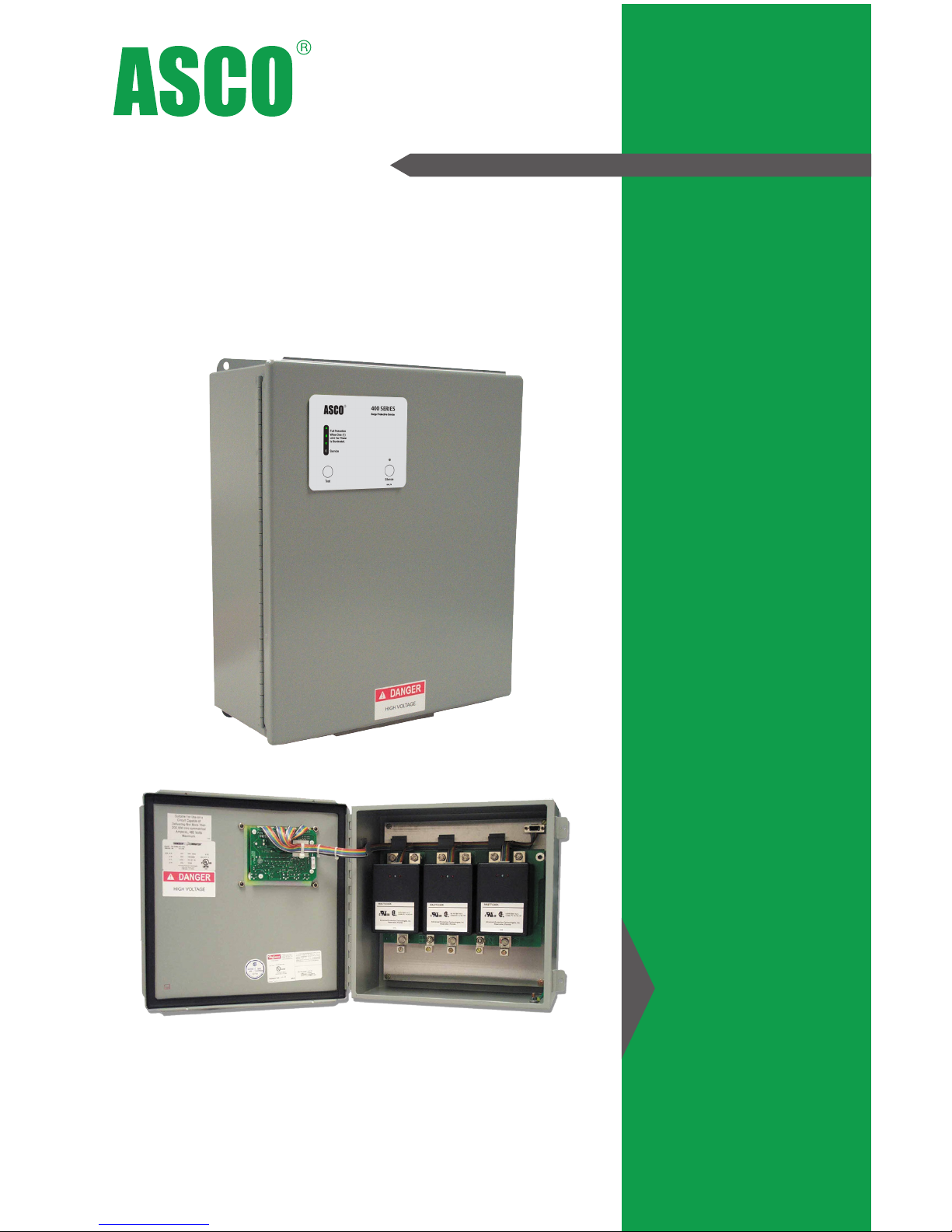
Surge Protective Devices
Installation & Operation Manual
Model 457
Page 2

Installation, Operation and Maintenance Manual IO-70063 RevD 03-182
V
Safety First – Hazardous Voltage & Shock Hazard
WARNING – IMPORTANT – PLEASE READ – WARNING
• Only qualified licensed electricians should install or service SPDs
• Hazardous voltages exist within SPDs
• SPDs should never be installed or serviced when energized
• Use appropriate safety precautions including Personal Protection Equipment
• Failure to follow these instructions can result in death, serious injury, and/or
equipment damage
• This manual shall be read in its entirety prior to installing
Bonding and Grounding Hazard
Verify that the neutral conductor in the service entrance equipment is bonded to ground in accordance
with the National Electric Code (NEC®), Canadian Electrical Code (CEC) and all applicable codes.
Verify that the neutral terminal (XO) on the secondary side of distribution transformers are grounded to
the system ground in accordance with the NEC®, CEC and all applicable codes.
During installation into an electrical system, the SPD must not be energized until the electrical system is
completely installed, inspected and tested. All conductors must be connected and functional including
the neutral (if required). The voltage rating of the SPD and system must be verified before energizing
the SPD.
Failure to follow these guidelines can lead to abnormally high voltages at the SPD. This may cause the
SPD to fail. The warranty is voided if the SPD is incorrectly installed and/or if the neutral conductor in
the service entrance equipment or downstream of separately derived systems is not bonded to ground
in accordance with the NEC® or CEC.
Do Not Hi-Pot Test SPDs
Any factory or on-site testing of power distribution equipment that exceeds normal operating voltage
such as high-potential insulation testing, or any other tests where the suppression components will be
subjected to higher voltage than their rated Maximum Continuous Operating Voltage (MCOV) must be
conducted with the SPD disconnected from the power source. For 4-wire systems, the neutral connection
at the SPD must also be disconnected prior to performing high-potential testing and then reconnected
after test completion.
Failure to disconnect SPD and associated components during elevated voltage testing will damage the
SPD and will void the warranty.
Page 3

Installation, Operation and Maintenance Manual IO-70063 RevD 03-183
ASCO SURGE PROTECTIVE DEVICE
INSTALLATION, OPERATION AND MAINTENANCE MANUAL
TABLE OF CONTENTS
INTRODUCTION
Major Industry Nomenclature Changes Eective 2008-2009
Figure 1: NEC® Article 285 & UL 1449-4
4
4
4
PRE-INSTALLATION & INSTALLATION PLANNING
Operating Environment
Audible Noise
Mounting, Dimensions, and Weight
Service Clearance
Maximizing SPD Performance
Cascade Surge Protection
Overcurrent Protection
Circuit Breaker and Disconnect Switch
Wire Size and Installation Torque
6
6
7
7
7
7
8
8
8
8
SPECIAL ENCLOSURE CONSIDERATIONS
Removing and Reconnecting the Ribbon Cables
NEMA Type 4X Enclosure
Figure 2: Flush Mount Front & Side View
Flush Mount Option
Terminals
Shortest Leads Possible
Voltage Rating
System Grounding
UL 1283 Required Language Concerning the Installation of EMI Filters
8
8
9
9
9
10
10
10
11
11
GENERAL INFORMATION
Simplified Explanation of Operation
Precautionary Statement Regarding SPDs on Ungrounded Systems
Cascade Surge Protection
Parallel Connection
Unpacking & Preliminary Inspection
Storage Environment
Table 1: Model Number Decoder
5
5
5
5
5
5
5
6
MAINTENANCE
Troubleshooting & Service
Figure 16: Troubleshooting Flowchart
Module Removal & Replacement Instructions
Display/Diagnostic Board Removal and Replacement
Preventive Maintenance (Inspection and Cleaning)
Corrective Maintenance (Repair)
Limited Warranty
Table 2: Replacement Parts
18
18
18
19
19
19
19
20
21
INSTALLATION
Figure 3: Typical Panel Installation
Figures 4-9: Electrical Connection Diagrams
Figure 10: Display Panels
Control and Diagnostic Panel
Service LED and the Audible Alarm
Figure 11: SPD Dimensions: NEMA Type 1, 4, And 4X Stainless Steel
Figure 12: SPD Dimensions: NEMA Type 3R
Figure 13: SPD Dimensions: NEMA Type 4X Plastic
Surge Counter Options
Figure 14: Module LEDs
Supplemental LED Indicators on Modules
Figure 15: Pinout Diagram For Dry Contacts Of SPD
Dry Contact Option
Remote Monitor Accessory Option
12
12
13
14
14
14
15
15
15
16
16
16
17
17
17
Page 4
Installation, Operation and Maintenance Manual IO-70063 RevD 03-184
INTRODUCTION
Thank you for choosing an ASCO Surge Protective Device (SPD). This is a high quality, high energy surge
suppressor designed to protect sensitive equipment from damaging transient overvoltages.
Proper installation is important to maximize performance. Please follow steps outlined herein.
This entire Operation & Maintenance Manual should be read prior to beginning installation. These
instructions are not intended to replace national or local codes. Follow all applicable electrical codes to
ensure compliance. Installation of this SPD should only be performed by qualified electrical personnel.
ASCO SPDs are extensively tested in accordance with industry standards such as ANSI/IEEE C62.41.1,
C62.41.2, C62.45, C62.62, C62.72, UL 1449, UL 1283, IEC 61643, etc.
This SPD is a single-port parallel-connected device intended for service entrance, panelboard or
downstream installation for IEEE Category C, B or A applications.
Major Industry Nomenclature Changes Eective 2008-2009
Be aware that UL 1449 Fourth Edition and 2008 NEC® Article 285 generated substantial changes.
• The term TVSS changed to SPD
• Types 1, 2, 3 & 4 SPDs are created
• UL 1449 clamping voltage performance testing changed from 500A to 3,000A
• UL 1449 added new I nominal testing (In), which consists of more rigorous duty-cycle testing
This SPD complies with the latest regulatory actions and is UL Listed as such.
For further information, please review latest editions of NEC® Art. 285, UL 1449 or contact ASCO Tech
Support at (800) 237-4567.
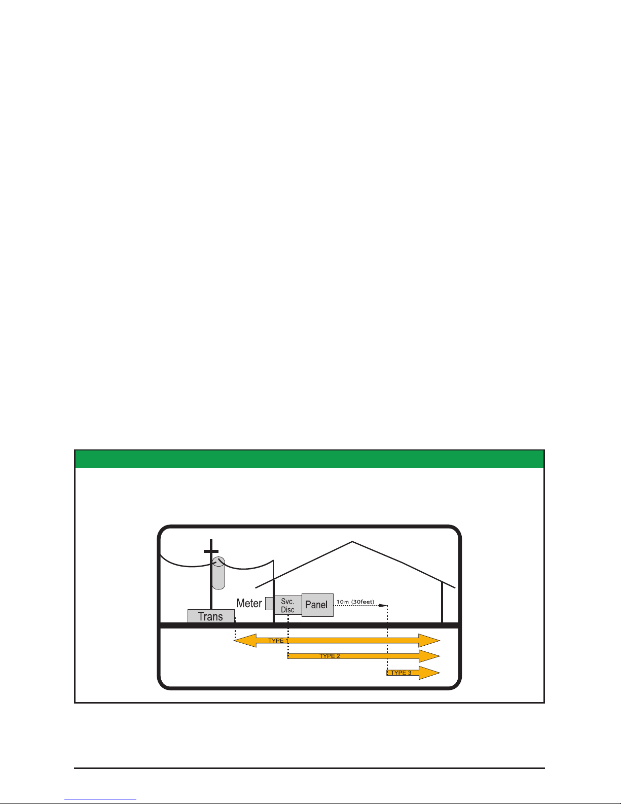
FIGURE1: NEC® ARTICLE 285 & UL 14494
SPD Types: Types 1, 2, & 3
Based on Location within electrical distribution system
(also coincides with ANSI/IEEE C62.41.2 - 2002 Categories C, B & A)
Page 5

Installation, Operation and Maintenance Manual IO-70063 RevD 03-185
GENERAL INFORMATION
This is a Type 2 SPD. It includes internal overcurrent protection. Type 2 SPDs are suitable for installation
on the load side of the service disconnect overcurrent device.
This device features internal overcurrent and overtemperature protection that will disconnect eected
surge suppression components at the end of their useful life, but will maintain power to the load – now
unprotected. If this situation is undesirable for the application, follow these instructions for servicing or
replacing the device.
Service of this unit consists of replacing internal modules and/or display assembly.
There are no user-serviceable parts inside the replaceable modules. Do not attempt to disassemble the
module as it stores charge and is potted.
Simplified Explanation of Operation
SPDs sense overvoltage and create a momentary short circuit to redirect harmful surge energy to earth
ground. Then they reset automatically and wait for the next surge. This is similar to the pressure relief
valve on a water heater: pressure goes up, valve opens to relieve pressure and then resets. In an electrical
system, an SPD senses overvoltage, shorts temporarily sending energy to ground and then resets. SPDs
are capable of repeating this function thousands of times.
Parallel Connection
This is a Parallel connected SPD – not series connected. As outlined above, an SPD ‘drains o’ excessive
voltage from an electrical system. Because of parallel connection, installation of the SPD near the
equipment to be protected is satisfactory. This eect is similar to flushing any toilet in a house; pressure
in the shower goes down. In an electrical system, a parallel connected SPD will remove excessive voltage
o the entire system (assuming reasonable proximity).
Tip: It is critically important that wiring leads be configured as short & straight as possible. Avoid long leads.
Avoid sharp bends. Route SPD conductors in the same conduit. Leads do not have to be sized for the entire load
– this SPD is parallel connected, not series connected. As a generalization, 6 AWG works fine.
Precautionary Statement Regarding SPDs on Ungrounded Systems
Caution – Ungrounded systems are inherently unstable and can produce excessively high line-to-ground
voltages during certain fault conditions. During these fault conditions, any electrical equipment including
an SPD, may be subjected to voltages which exceed their designed ratings. This information is being
provided to the user so that an informed decision can be made before installing any electrical equipment
on an ungrounded power system.
Unpacking & Preliminary Inspection
Inspect the entire shipping container for damage or signs of mishandling. Remove the packing materials
and further inspect the unit for any obvious shipping damages.
If any damage was found and is a result of shipping or handling, immediately file a claim with the shipping
company and forward a copy to ASCO.
Storage Environment
This SPD should be stored in a clean, dry environment. Storage temperature range is -40°C (-40°F) to
+60°C (+140°F). Avoid exposure to high condensation.
Page 6
Installation, Operation and Maintenance Manual IO-70063 RevD 03-186
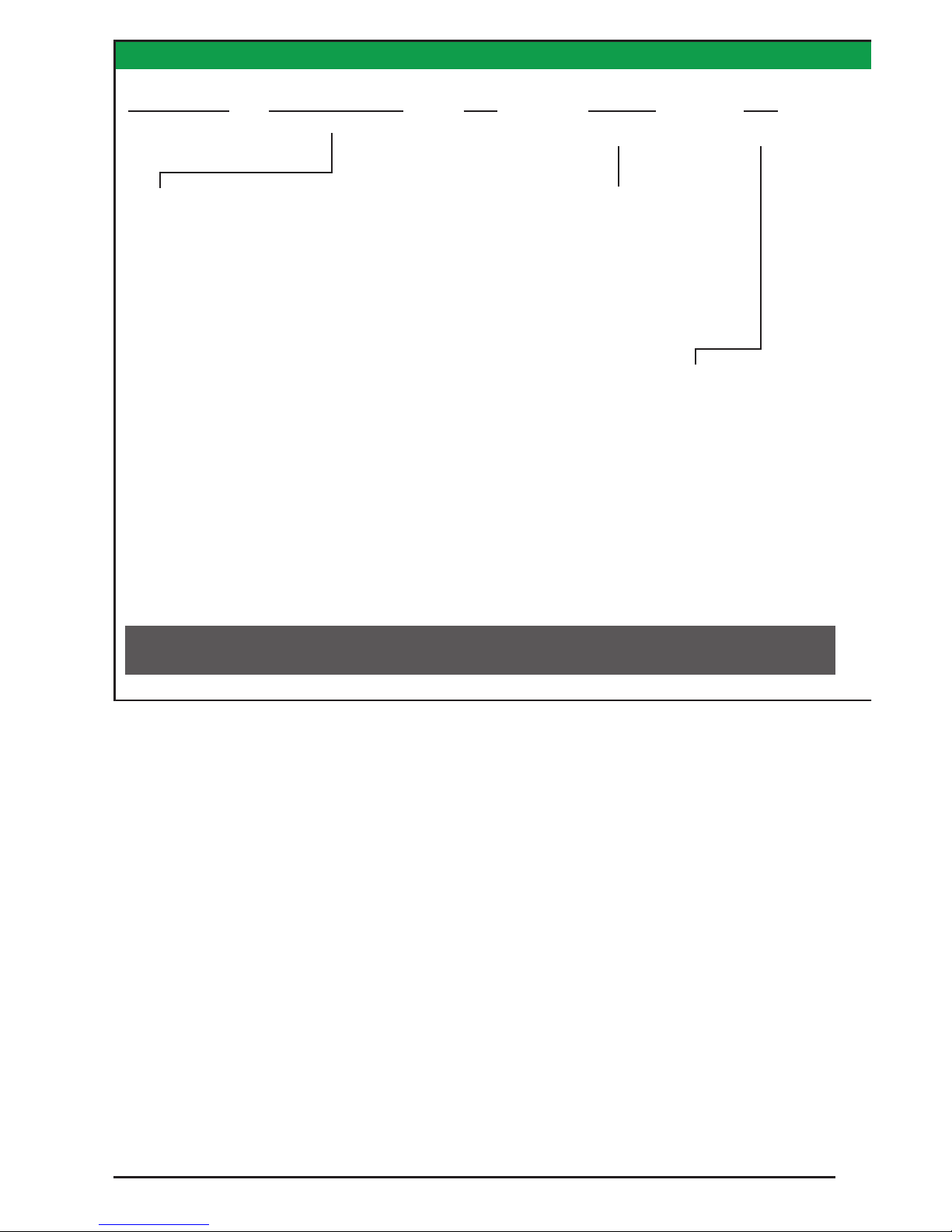
TABLE 1: MODEL NUMBER DECODER TABLE 1: MODEL NUMBER DECODER
PRE-INSTALLATION & INSTALLATION PLANNING
Operating Environment
The standard unit is in a Type 1 enclosure. Other enclosure types are available as options. Before installing,
ensure that your enclosure type and application are appropriate per NEMA 250 with regard to moisture,
dirt, excessive dust, flammable materials or atmospheres, corrosive vapors, etc.
This SPD is designed in an ambient temperature range of -40°C (-40°F) to +60°C (+140°F) with a relative
humidity of 0% to 95% (non-condensing). Excessive temperature may inadvertently operate internal
thermal overtemperature protectors.
Audible Noise
SPD background noise is negligible or non-existent, and does not restrict the location of installation.
Mounting, Dimensions, and Weight
This SPD is designed to be wall mounted. The standard enclosure is: 12” x 12” x 7.5” (L/W/D), and the
weight is 25 lbs.
Example: 457120SP16ACAE20 - Model 457, 240/120V Split Phase, 160kA, Standard Modes, Compression Lugs or Terminals,
LEDs/Audible Alarm/Relay, NEMA 1/12/3R/4, Type 2, No Accessories or Options
Voltage Codes
P
Per Phase
kA Rating
System
Modes of
Protection
kA Rating
Per Phase
A = All Standard
Modes for that
Product Line &
Voltage Code
Series/
Product Line
457
Common North American Systems
120S = 240/120V Split Phase - 1Ø, 3W+Grnd, (Fig 1)
120Y = 208Y/120V Wye - 3Ø 4W+Grnd, (Fig 2)
240H = 240/120V High Leg Delta (B High), (Fig 3)
277Y = 480Y/277V Wye - 3Ø 4W+Grnd, (Fig 2)
347Y = 600Y/347V Wye - 3Ø 4W+Grnd, (Fig2)
480D = 480V Delta - 3Ø 3W+Grnd, (Fig4) & HRG Wye
Other Available Systems - Confirmation Encouraged
120N = 120V Single Phase, 1Ø 2W+G (Fig 5)
240N = 240V Single Phase, 1Ø 2W+G (Fig 5)
220Y = 380Y/220V Wye - 3Ø 4W+Grnd (Fig 2)
240C = 240V B Corner Grnd Delta, 3Ø 3W+Grnd (Fig 6)
240D = 240V Delta - 3Ø 3W+Grnd (Fig 4)
480C = 480V B Corner Grnd Delta, 3Ø 3W+Grnd (Fig 6)
600C = 600V B Corner Grnd Delta, 3Ø 3W+Grnd (Fig 6)
600D = 600V Delta - 3Ø 3W+Grnd (Fig 4) & HRG Wye
16 = 160kA
24 = 240kA
09 = 90kA (SAD)
13 = 130kA (SAD)
17 = 170kA (SAD)
(SAD available in 120S
& 120Y)
Page 7
Installation, Operation and Maintenance Manual IO-70063 RevD 03-187
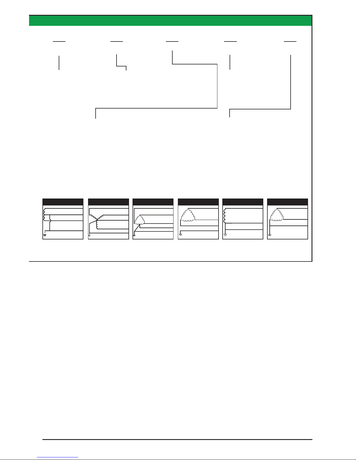
Figure 1
SPLIT
2 Phase, 1 Neutral,
1 Ground
Phase B (Black)
Phase A (Black)
Neutral (White)
V
V
}
}
Ground (Green)
Figure 2
WYE
3 Phase, 1 Neutral,
1 Ground
}
Phase A (Black)
Phase B (Black)
Neutral (White)
Phase C (Black)
Ground (Green)
A
C
N
V
B
Figure 3
HI-LEG DELTA (B High)
3 Phase, (B HIGH),
1 Neutral, 1 Ground
Phase A (Black)
Phase B (Orange)
Neutral (White)
Phase C (Black)
Ground (Green)
}
V
Figure 5
SINGLE POLE
1 Phase, 1 Neutral,
1 Ground
V
}
Neutral (White)
Phase A (Black)
Ground (Green)
Figure 4
DELTA & HRG WYE
3 Phase, 1 Ground
Phase A (Black)
Phase C (Black)
Phase B (Black)
Ground (Green)
}
V
Figure 6
CORNER GROUND
DELTA (B grounded)
2 Phase, 1 Ground
Phase A (Black)
Phase C (Black)
Ground (Green)
V
}
Connection
Typ e
C = Compression
Lugs or Terminals
(No Wires Included)
Monitoring
Options
Enclosure
UL 1449
Type1/Type 2
Accessory/
Option(s)
2 = Type 2
(Includes
UL1283 Filter)
0 = No Accessory/Option
X = Yes Accessory/Option
Service Clearance
Service clearance is needed at the front of the Model 457 unit only, 36 inches minimum is the required
distance for clearance pursuant to the NEC®.
Maximizing SPD Performance
SPD’s must be located as close to the circuit as possible to minimize parasitic losses. Surges are high
current, high frequency events that cause substantial voltage drops across conductors. This hurts SPD
performance. Use the shortest & straightest possible leads. Pre-Plan installations and ensure that nearest
breaker positions are used. If new construction, adjust breaker locations as appropriate.
Tip: Voltage drops for normal 120V or 277V lines might be 2-3V per hundred feet. In surge applications, voltage
drops might be 100-150V per foot. These voltage drops add to clamping voltage, thus hurting performance.
Make every eort to keep leads short and straight.
As distribution gear becomes larger, shorter leads are more diicult to accomplish. When longer leads are
unavoidable, gently twist leads together (one to two twists per foot), or tie-wrap leads together.
E = NEMA 1/12/3R/4 (metal combo)
Size - 12” x 12” x 7.5”
J = NEMA 4X (polycarbonate, display inside door)
Size - 14” x 12” x 6”
H = NEMA 4X (stainless, display inside door)
Size - 12” x 12” x 6”
Q = Flush Mount, Wall Cavity Size - 12” x 12” x 6”
X = Smaller Enclosure, Size - 10” x 10” x 6”
N = No Enclosure (includes aluminum backplane)
U = LED(s)/Aud. Alarm
A = LED(s)/Aud. Alarm/Relay
C = LED(s)/Aud. Alrm/Relay/
Surge Counter
Page 8

Installation, Operation and Maintenance Manual IO-70063 RevD 03-188
Tip: surges create magnetic fields per the ‘right-hand rule’. When current goes in direction of thumb, magnetic
field is in direction of curl of fingers. As surge current goes to SPD, fields are created in one direction. When the
SPD sends those currents to neutral and/or ground, current goes in the opposite direction. If ‘coming & going’
are on the same axis, the magnetic fields can be cancelled, thus avoiding performance decrease. Gentle twists,
bundling & tie-wraps accomplish this.
Cascade Surge Protection
For optimum surge protection, cascade or staged surge suppression should be implemented at the
service entrance and downstream locations as appropriate. Known or expected surge sources, as well as
sensitive loads, should also have localized surge suppression. For interconnected electronic loads (data
cabling), SPDs should also be utilized to protect the devices on either end of the interconnecting data
cables.
Overcurrent Protection
SPDs draw very little current under normal conditions and conduct for a brief duration upon encountering
a transient surge current. This SPD contain internal overcurrent and overtemperature protection to
protect against abnormal voltage conditions.
Supplemental overcurrent protection is not required to protect this SPD. However, connecting conductors
require protection in Type 2 or 4 applications. Follow applicable codes.
Circuit Breaker and Disconnect Switch
This Model 457 family SPD is tested and qualified as a Type 2 SPD per UL 1449 Fourth Edition and 2008
NEC®. This SPD can be installed on the load side of the service overcurrent device per 2008 NEC® Article
285.
When connected on load side of main disconnect, we suggest connecting via a 60A circuit breaker. The
circuit breaker is the intended disconnect switch and provides short circuit protection to the connecting
conductors. Model 457 has internal overload protection elements within the product. A breaker or
disconnect is not required for the SPD’s overcurrent protection. Model 457 SPDs have demonstrated
200kA Short Circuit Current Ratings (SCCR). Confer to label on unit.
Wire Size and Installation Torque
This is a parallel-connected SPD; it is not series-connected. The size of the SPD wiring is independent of
the ampere rating of the protected circuit. Recommended wire is 6 AWG for phase, neutral and ground
connections. Torque connections to 18 inch-pounds. Conductor length should be as short as possible.
If other wire sizes are used, we recommend that all conductors be the same gauge. Note that larger
conductor might appear to be beneficial; however, it tends to have the same inductance as smaller
conductor and is more diicult to work with.
Terminals accept 14 - 2 AWG conductor with 6 AWG being preferred. Coordinate conductor size and
overcurrent
SPECIAL ENCLOSURE CONSIDERATIONS
Removing and Reconnecting the Ribbon Cables
The ribbon cables are marked with matching phase connections. If any of the cables are removed,
reconnect the cables as marked.
Page 9

Installation, Operation and Maintenance Manual IO-70063 RevD 03-189
NEMA Type 4X Enclosure
On rare occasions in high temperature climates, Model 457’s inside clear-cover polycarbonate
enclosures have experienced internal temperatures exceeding 200°F. This inadvertently operates the
overtemperature safety disconnectors inside the SPD. We recommend positioning the unit so that the
clear front avoids direct summer sunlight by shading or not facing west.
The NEMA Type 4X enclosure is shipped with its mounting brackets and installation screws packaged
inside it. Use the enclosed 1/4-20 x 1/2 in. slotted screws to secure the brackets to the enclosure before
installing the Model 457 SPD device. Torque these screws to a maximum of 50lb-in. (6N·m). When
installing the cover for the NEMA Type 4X enclosure, torque the cover screws to a maximum of 25lbs-in.
(3 N·m).
Flush Mount Option
Remove the display panel and barrier before making any electrical connections. Replace the barrier and
display panel before energizing the device.
Model 457 is approximately 5.25 in. (133 mm) deep. It will not flush mount unless there is at least 5.25 in.
(133 mm) of clearance. Model 457 is not designed to flush mount on a typical 2 x 4 stud wall.
Follow steps 1-5 to flush mount Model 457.
1. Before removing the trim, disconnect the ribbon cables and ground wire from the modules.
2. Mount the device as close as possible to the panel being protected. Create a wall opening slightly
larger than 12 in. high by 12 in. wide (305 mm high by 305 mm wide). See figure 2.
3. Install a backing plate inside the wall cavity 5.25 in. (133 mm) from the wall face such that Model 457
will be supported from its back. See figure 3. Note the mounting holes on the back of the enclosure.
Also note that Model 457 weighs 25 lb (12 kg) maximum.
4. Configure the electrical conductor and conduit connections consistent with the wiring instructions
beginning on page 7.
5. Carefully reattach the ribbon cables and the ground wire to the modules and reattach the display
panel/cover before energizing and testing the device ground at the service equipment or other
acceptable building earth ground such as the building frame in the case of a high-rise steel-frame
structure.
FIGURE 2: FLUSH MOUNT FRONT & SIDE VIEW
Page 10

Installation, Operation and Maintenance Manual IO-70063 RevD 03-1810
Terminals
Terminals will accept 14 - 2 AWG conductor and are provided for line (phase), neutral (if used), and
equipment safety ground connections. 8 AWG is the minimum recommended wire size because UL
testing and evaluation was performed using 8 AWG.ators to ensure proper operation. We also recommend
keeping the SPD clean as appropriate.
Shortest Leads Possible
• Leads must be as short and straight as possible - See NEC® Article 285.12
• Pretend wire is $1000 per foot coming out of your pocket
• No long leads
• No sharp bends
• No wire nuts
• How short is short enough? As short as you can make it
• How long is too long? If anyone else can make it shorter
Voltage Rating
Before installing SPD, verify that it has the same voltage rating as the power distribution system. Compare
the SPD’s nameplate voltage or model number and ensure that SPD configuration matches the intended
power source. See Table 1.
The specifier or the user of the device should be familiar with the configuration and arrangement of the
power distribution system in which any SPD is to be installed. The system configuration of any power
distribution system is based strictly on how the secondary windings of the transformer supplying the
service entrance main or load are configured. This includes whether or not the transformer windings
are referenced to earth via a grounding conductor. The system configuration is not based on how any
specific load or equipment is connected to a particular power distribution system.
480V System Example: SPDs should be installed per the electrical system, not per a load or motor’s wiring
connection. For example, a 480V three phase motor might appear to be connected as a 480V Delta. In
actuality, the serving distribution system might be a 480Y/277V grounded Wye, with or without a neutral
pulled to the motor or MCC. The system is still a 480Y/277V Wye, even though the load is connected
as a Delta. A grounded Wye has a defined reference to ground (i.e., neutral is bonded to ground). Some
Delta systems are ungrounded, which have no reference to ground and are known to become unstable
in certain situations. Such instability can cause line to ground voltage fluctuations that may prematurely
fail SPDs. For this reason, the NEC® Article 285 has placed SPD restrictions on ungrounded systems. As
generalizations, SPDs for ungrounded systems can be installed on grounded systems with a clamping
performance penalty. However, SPDs for grounded systems installed on ungrounded systems are
almost certainly destined for premature failure. Call ASCO Tech Support at (800) 237-4567 for further
information.
Page 11

Installation, Operation and Maintenance Manual IO-70063 RevD 03-1811
System Grounding
An equipment grounding conductor must be used on all electrical circuits connected to the SPD.
For the best performance, use a single point ground system where the service entrance grounding
electrode system is connected to and bonded to all other available electrodes, building steel, metal water
pipes, driven rods, etc. (for reference see: IEEE Std 142-2007).
For sensitive electronics and computer systems, we recommend that the ground impedance measurement
be as low as possible. When metallic raceway is used as an additional grounding conductor, an insulated
grounding conductor should be run inside the raceway and sized per the NEC®. Adequate electrical
continuity must be maintained at all raceway connections. Do not use isolating bushings to interrupt a
metallic raceway run.
A separate isolated ground for the SPD is NOT recommended. Proper equipment connections to
grounding system and ground grid continuity should be verified via inspections and testing on a regular
basis as part of a comprehensive electrical maintenance program.
On 4-Wire Power Systems, neutral to ground bonding (Main Bonding Jumper) must be installed per the
NEC®. Failure to do so WILL damage SPDs.
UL 1283 required language concerning the installation of EMI Filters
a. An insulated grounding conductor that is identical in size and insulation material and thickness to
the grounded and ungrounded circuit supply conductors, except that it is green with or without
one or more yellow stripes, is to be installed as part of the circuit that supplies the filter. Reference
should be made to Table 250-122 of the National Electrical Code regarding the appropriate size of
the grounding conductor.
b. The grounding conductor mentioned in item “a” is to be grounded to earth at the service equipment
or other acceptable building earth ground such as the building frame in the case of a high-rise steelframe structure.
c. Any attachment-plug receptacles in the vicinity of the filter are to be of a grounding type, and the
grounding conductors serving these receptacles are to be connected to earth ground at the service
equipment or other acceptable building earth ground such as the building frame in the case of a
high-rise steel-frame structure.
d. Pressure terminal or pressure splicing connectors and soldering lugs used in the installation of the
filter shall be identified as being suitable for the material of the conductors. Conductors of dissimilar
metals shall not be intermixed in a terminal or splicing connector where physical contact occurs
between dissimilar conductors unless the device is identified for the purpose and conditions of use.
Page 12

Installation, Operation and Maintenance Manual IO-70063 RevD 03-1812
INSTALLATION
Common Problems to Avoid
• Confirm System voltage to SPD voltage (120V SPD will fail instantly on 240V, 277V, etc.).
• Locate SPD close so leads are short & straight as possible (or will seriously hurt performance).
• Make sure N-G or XO bonding meets NEC® (or will prematurely fail SPD).
• Energize SPD AFTER system is stabilized & checked (inadvertent system problem may fail SPD).
• SPDs are regulated by NEC® Article 285 and UL 1449.
• Never Hi-Pot test any SPD (will prematurely fail SPD).
Pre-Plan your installation. You will need to accomplish the following:
• Meet all National and Local codes (NEC® Article 285 addresses SPDs).
• Mount SPD as close to panel or equipment as possible to keep leads short.
• Ensure leads are as short and straight as possible, including neutral and ground. Consider a
breaker position that is closest to the SPD and the panel’s neutral & ground.
• Suggested breaker & conductor size is 60A-30A with 6 AWG (60A preferred).
• Make sure system is grounded per NEC® and clear of faults before energizing SPD.
1. Use a voltmeter to check all voltages to ensure correct SPD.
2. If SPD has Dry Contact, Remote Monitoring or Remote Display, pre-plan their installation
3. Remove power for panel. Confirm panel is deenergized.
4. Identify breaker location and SPD location.
5. Make sure leads are short! Reducing inches matters!
Pretend that connector leads cost you $1000 per foot!
6. Remove an appropriately sized knockout from panel.
Create an appropriately sized hole in the SPD enclosure.
7. Mount SPD.
8. Connect conductors as appropriate – short and straight as possible
(Note that Hi-Legs are Phase B).
9. Label or mark conductors as appropriate
(neutral: white, ground: green, energized: black, hi-leg: orange).
10. Make sure system is bonded per NEC® and is clear of hazards or faults before energizing
(N-G bonding not per NEC® will fail SPDs: #1 cause of SPD failures).
11. Energize and confirm proper operation of indicators and/or options.
FIGURE 3: TYPICAL PANEL INSTALLATION
A
BC
GN
BREAKER
▪ Use closest breaker to SPD
▪ Locate SPD close to intended breaker
▪ Keep Leads Short as Possible
▪ Avoid Sharp Bends
▪ Outdoor installation requires appropriate
weather sealing at nipple (o-ring, sealing
condulet, etc.)
To Protected Loads
Page 13

Installation, Operation and Maintenance Manual IO-70063 RevD 03-1813
FIGURE 4
FIGURE 6
FIGURE 8
FIGURE 5
FIGURE 7
FIGURE 9
SPLIT
2 Phase, 1 Neutral,
1 Ground
Phase B (Black)
Phase A (Black)
Neutral (White)
V
V
}
}
Ground (Green)
WYE
3 Phase, 1 Neutral,
1 Ground
}
Phase A (Black)
Phase B (Black)
Neutral (White)
Phase C (Black)
Ground (Green)
A
C
N
V
B
HI-LEG DELTA (B High)
3 Phase, (B HIGH),
1 Neutral, 1 Ground
Phase A (Black)
Phase B (Orange)
Neutral (White)
Phase C (Black)
Ground (Green)
}
V
DELTA
3 Phase, 1 Ground
Phase A (Black)
Phase C (Black)
Phase B (Black)
Ground (Green)
}
V
CORNER GROUND
DELTA (B grounded)
2 Phase, 1 Ground
Phase A (Black)
Phase C (Black)
Ground (Green)
V
}
SINGLE POLE
1 Phase, 1 Neutral,
1 Ground
V
}
Neutral (White)
Phase A (Black)
Ground (Green)
Electrical Connection Diagrams
Page 14

Installation, Operation and Maintenance Manual IO-70063 RevD 03-1814
Control and Diagnostic Panel
All indicators and controls are located on the front diagnostic panel. Green LEDs indicate correct
operation.
Phase A, B & C: Tri-Color LED status indicators – one per phase
Green – Full Protection
Amber – Partial Protection
Red – No Protection
Service LED (red): LED illuminates in the event of problem. This indicator is logic-connected to the
Phase LEDs. Should a Phase LED go out, the red Service LED will illuminate and the Audible Alarm will
sound.
Test: Tests red Service LED and Audible Alarm regardless of Alarm Silence status; does not cycle optional
dry contacts
Alarm Silence: Turns Audible Alarm o (Audible Alarm is deactivated when LED is illuminated)
Surge Counter Count: (if equipped) Increments optional surge counter by one (+1)
Surge Counter Reset: (if equipped) Resets optional surge counter to zero (0)
If an inoperative condition where to occur, the built-in audible alarm will sound and the red Service LED
will illuminate. This indicates that the unit needs evaluation by a qualified electrician or technician. Until
a qualified person evaluates the unit, press Alarm Silence to silence the alarm. (The LED above Alarm
Silence illuminates when the alarm is deactivated. Normal operation occurs with the Alarm Silence LED
extinguished.) The red Service LED will remain illuminated even though the Audible Alarm has been
silenced. Test tests the red.
FIGURE 10: DISPLAY PANELS
Model 457 Control and Diagnostics Panel
Service
Full Protection
When One (1)
LED Per Phase
Is Illuminated.
Silence
9295_R1
Test
400 SERIES
Surge Protective Device
Page 15

Installation, Operation and Maintenance Manual IO-70063 RevD 03-1815
FIGURE 13: SPD DIMENSIONS: NEMA TYPE 4X PLASTIC
FIGURE 12: SPD DIMENSIONS: NEMA TYPE 3R
FIGURE 11: SPD DIMENSIONS: NEMA TYPE 1, 4, AND 4X STAINLESS STEEL
Page 16

Installation, Operation and Maintenance Manual IO-70063 RevD 03-1816
Service LED and the Audible Alarm
Diagnostics will indicate a failure upon loss of voltage or significant drop in voltage. Be aware that ground
faults on ungrounded or resistive ground systems will trigger a failure alarm on this SPD.
If LEDs are illuminated in a manner that suggests contradictory information, there may be an internal logic
problem and the unit needs replaced. If none of the LEDs are illuminated, the unit may not be installed
correctly. For troubleshooting assistance, please contact ASCO Technical Support at (800) 237-4567.
Surge Counter Options
The surge counter registers the number of transient overvoltages on all L-N and L-G modes since the
counter was last reset. The counter is inductively coupled from each mode of protection. It increments
upon significant current change in a short time period (large di/dt).
The surge counter includes Test and Reset buttons on the touchpad display. Pressing Test adds one
count. Pressing Reset clears the counter’s memory and sets the display to zero.
The counter option includes a SuperCap internal storage capacitor that provides backup power for up to
four days in the event of a power outage. This eliminates the maintenance of battery backups. There is a
10-15 minute charging cycle before the counter(s) operate.
Single Counter – Totals the surges through the L-N and L-G
Supplemental LED indicators on Modules
Each module includes three LEDs per Figure 14. The center green LED indicates power is on. This green
LED should be illuminated during normal operation.
When the upper left red LED is illuminated, the module’s L-G protection is lost.
When the upper right red LED is illuminated, the module’s L-N protection is lost.
FIGURE 14: MODULE LEDS
Green LED lit:
power on
Red LED lit:
loss of surge
suppression
from line to
neutral
Red LED lit:
loss of surge
suppression
from line to
ground
Page 17

Installation, Operation and Maintenance Manual IO-70063 RevD 03-1817
Dry Contact Option
Model 457 is available with optional Dry Contacts which utilize a DB-9 connector. This feature provides
two sets of normally open (N.O.) and normally closed (N.C.) contacts through the DB-9 connector. These
relay contacts can be used for remote indication of the SPD’s operating status. Examples could include
a computer interface board, an emergency management system, etc. The relay contact pin arrangement
is outlined in Table 2. (Please note the jumpered connections. Pins 7, 8 & 9 were used to drive an earlier
version of the Remote Monitor option. Pins 7, 8 & 9 do not represent a third set of contacts. Pin pairs 4
& 7, 5 & 8, and 6 & 9, are connected via jumper internally. The combined current of each pin pair may not
exceed 1 Ampere).
An optional Remote Monitor accessory is available that will provide visual and audible indication of an
alarm condition. The Remote Monitor requires the Dry Contact option as it collects information through
the Dry Contact’s DB-9 connection. Please note that the DB-9 connector is completely utilized by the
optional remote monitoring accessory. If the Remote Monitor is used, there will be no means to interface
with another device.
For custom applications using the Dry Contacts, please note the following information:
• The Dry Contacts are designed for low voltage or control signals only.
• Maximum switching current is 1 amp.
• Maximum switching voltage is 24 volts, DC or AC.
Higher energy application may require additional relay implementation outside the SPD. Damage to the
SPD’s relay caused by implementation with energy levels in excess of those discussed in this manual will
not be covered by warranty. If you have design questions, please contact ASCO Technical Support at:
1.800.237.4567.
Remote Monitor Accessory Option
A Remote Monitor is available for remote annunciation. It requires a standalone 120V power source (wall
plug transformer) and uses one set of Form C Dry Contacts. The Remote Monitor can be configured
to monitor several ASCO SPDs simultaneously. Installation is detailed in a separate document. Contact
factory as appropriate.
FIGURE 15: PINOUT DIAGRAM FOR DRY CONTACTS OF SPD
Using DB-9 Syle
Connector:
1 Normally Closed
2 Common
3 Normally Open
4 Normally Closed
5 Common
6 Normally Open
7 Connected to Pin 4
8 Connected to Pin 5
9 Connected to Pin 6
1
2
3
4
5
6
7
8
9
Form C Set #2
Form C Set #1
Normally Closed
Common
Normally Open
Normally Closed
Common
Normally Open
Connected to Pin 4
Connected to Pin 5
Connected to Pin 6
Form C Set #2
Form C Set #1
Page 18

Installation, Operation and Maintenance Manual IO-70063 RevD 03-1818
MAINTENANCE
SPDs require minimal maintenance. We recommend periodic inspection of diagnostic indicators to ensure
proper operation. We also recommend keeping the SPD clean as appropriate.
Troubleshooting & Service
Please contact us for any service related issues. We want to take care of any problems.
Quality SPDs are designed and tested to withstand severe duty. However, there are various electrical
anomalies that SPDs cannot protect against. These are generally Sustained Overvoltages also known
as Temporary Overvoltages (TOVs). In this context, Sustained Overvoltages may be only a few cycles.
Failed SPDs tend to be symptoms, not root causes. A failed SPD should be treated as a ‘canary in the
coalmine’ suggesting further investigation as there may be a larger issue at play. Regardless of cause,
SPDs attempt to protect their load until failure.
As noted above, the single largest ‘killer’ of SPDs is reference to ground issues. If the SPD shows problems
on startup, there is reasonable chance of bonding/grounding/misapplication issue. This permanently
damages the unit. If not corrected, it will happen again.
Tip: Visually confirm N-G bonding. Be aware that a voltmeter measuring N-G can be misleading. For example,
N-G voltage could read 0V because neutral and ground are at the same potential purely by happenstance, not
because they are bonded. Visually confirm bonding.
FIGURE 16: TROUBLESHOOTING FLOWCHART
No
Yes
No
No
Yes
No
YesYes
No
No
No Yes
Yes
Possible 457
Control and
Diagnostics
Panelboard
Failure. Call ASCO
Tech Support.
Page 19

Installation, Operation and Maintenance Manual IO-70063 RevD 03-1819
Tip: Experience indicates that regulation-challenged generators can cause Sustained Overvoltages, as well as
ungrounded generators, and/or unusual load transfer systems.
Note: Prior to returning power or servicing the SPD, inspect the entire SPD for any other damaged
components. Any damaged components should be replaced prior to returning the SPD to service.
Module Removal & Replacement Instructions
Disconnect power to the SPD. Discharge internal capacitors by grounding. Unplug the 10 pin connector
from the Model 457 module. Using a 7/16” socket wrench, remove the bolts on both ends of the module,
and pull the module out. Make note of the location and part number of each module removed, as this part
number is not referenced anywhere else on the SPD. The module(s) should only be replaced with a new
module bearing the same part number as the module(s) previously removed. Replace with a new module
by reversing the procedure. Torque bolts to 65 inch-pounds, power up the SPD and verify the green
module LED is lit and all alarms have been cleared.
Display/Diagnostic Board Removal and Replacement
Disconnect power to the SPD. Remove the nuts from the switches that secure the board to the panel, then
remove the board. Remove the connectors one at a time from the existing board and insert them into the
appropriate connector on the replacement board. Install the replacement board into the panel and install
the nuts onto the switches and tighten securely.
Note that a sealing gasket between the display and the enclosure is a key component ensuring weather
resistance. Replace the gasket whenever the display is removed.
Preventive Maintenance (Inspection and Cleaning)
Inspection of the SPD should be performed periodically to maintain reliable system performance and
continued transient voltage surge protection. While it is diicult to establish a preventive maintenance
schedule because conditions vary from location to location, inspections for inoperative modules and
other signs of trouble utilizing the built-in diagnostics should be performed on a routine basis (weekly
or monthly).
Corrective Maintenance (Repair)
ASCO’s Surge Protective Devices are designed for years of reliable, trouble-free operation. Unfortunately,
even the most reliable equipment can become inoperative. On-line diagnostics are an integral part of
the SPD and will aid in isolating which of the protection module(s) have become inoperative. To keep
the SPD operating at peak performance, replacement of any inoperative module(s) should be performed
according to module removal and replacement instructions at the earliest service opportunity.
Troubleshooting procedures should be used to isolate other problems not associated with inoperative
module(s). See Figure 16, Troubleshooting Flow Chart on page 10 for assistance. Be sure to replace
components with identically rated parts to continue proper operation and safety. Table 2 lists typical
replacement parts.
Page 20

Installation, Operation and Maintenance Manual IO-70063 RevD 03-1820
Limited Warranty
ASCO warrants it’s AC panel protection products against defective workmanship and materials for 10
years (Optional warranty available) from the date of original purchase. The unit must have been installed
by a qualified and licensed electrician in order to quality for Warranty coverage.
Liability is limited to the replacement of the defective product. A Return Authorization (RA #) number
must be given by the company prior to the return of any product. Returned products must be sent to
the factory with the transportation charges prepaid. In addition, the company also warrants unlimited
replacement of modular and component parts within the warranty periods previously described.
ASCO specifically disclaims all other warranties, expressed or implied. Additionally, the company will
not be responsible for incidental or consequential damages resulting from any defect in any product or
component thereof.
Page 21

Installation, Operation and Maintenance Manual IO-70063 RevD 03-1821
TABLE 2: REPLACEMENT PARTS
Order # Description Used In
MA120V090K Module 120 VAC with LED 90kA
MA220V090K Module 220 VAC with LED 90kA
MA277V090K Module 277 VAC with LED 90kA
MA120V130K Module 120 VAC with LED 130kA
MA220V130K Module 220 VAC with LED 130kA
MA277V130K Module 277 VAC with LED 130kA
MA120V160K Module 120 VAC with LED 160kA
MA220V160K Module 220 VAC with LED 160kA
MA240V160K Module 240 VAC with LED 160kA
MA277V160K Module 277 VAC with LED 160kA
MA347V160K Module 347 VAC with LED 160kA
MA480V160K Module 480 VAC with LED 160kA
MA600V160K Module 600 VAC with LED 160kA
MA120V170K Module 120 VAC with LED 170kA
MA220V170K Module 220 VAC with LED 170kA
MA277V170K Module 277 VAC with LED 170kA
MA120V240K Module 120 VAC with LED 240kA
MA220V240K Module 220 VAC with LED 240kA
MA220V240K Module 240 VAC with LED 240kA
MA277V240K Module 277 VAC with LED 240kA
MA347V240K Module 347 VAC with LED 240kA
MA480V240K Module 480 VAC with LED 240kA
MA600V240K Module 600 VAC with LED 240kA
Page 22

Installation, Operation and Maintenance Manual IO-70063 RevD 03-1822
Page 23

Installation, Operation and Maintenance Manual IO-70063 RevD 03-1823
Page 24

IO-70063 RevD 03-18
14550 58th Street North
Clearwater, Florida 33760
P (800) 237-4567
P (727) 535-6339
F (727) 539-8955
E customercare@ascopower.com
While every precaution has been taken to ensure accuracy and completeness
in this literature, ASCO assumes no responsibility, and disclaims all liability for
damages resulting from use of this information or for any errors or omissions.
 Loading...