

Asco 425 Installation & Operation Manual
Surge Protective Devices
Installation & Operation Manual
Model 425

Installation, Operation and Maintenance Manual IO-70060 RevC 12-172

Installation, Operation and Maintenance Manual IO-70060 RevC 12-173
ASCO SURGE PROTECTIVE DEVICE
INSTALLATION, OPERATION AND MAINTENANCE MANUAL
TABLE OF CONTENTS
INSTALLATION
Figure 2: Leads Short & Straight
Figure 3:
Typical Panel Installation
Figure 4: Flush Mount Diagram
Figure 5: Dimensions & Weight
Table 1: Specifications
Voltage Rating & Application
SPDs on Ungrounded Systems
Connecting Optional Form C Dry Contact & Audible Alarm
Remote Indication Option
Figure 7: Leads
6
6
7
7
8
8
8
9
9
9
9
NORMAL OPERATION
Green LED Indicator
Form C Dry Contact and Audible Alarm Option
Maintenance
Troubleshooting & Service
10
10
10
10
10
INTRODUCTION
Industry Nomenclature Changes
Figure 1: NEC® Article 285 & UL 1449-4
Parts List
4
4
4
5
Installation, Operation and Maintenance Manual IO-70060 RevC 12-174
Thank you for choosing an ASCO Model 425 Surge Protective Device (SPD). Model 425 is a high
quality, high energy surge suppressor designed to protect sensitive equipment from damaging transient
overvoltages. Model 425 is parallel connected such that circuit ampacity is unlimited. Proper installation
is important to maximize performance. Please follow steps outlined herein. This entire Operation and
Maintenance Manual should be read prior to beginning installation. These instructions are not intended
to replace national or local codes. Follow all applicable electrical codes to ensure compliance. Installation
of this SPD should only be performed by qualified electrical personnel.
ASCO SPDs are extensively tested in accordance with industry standards such as ANSI/IEEE C62.41.1,
C62.41.2, C62.45, C62.62, C62.72, UL1449, UL 1283, IEC 61643, CSA C22.2 No. 269, etc.
Risk of Electric Shock
ONLY QUALIFIED LICENSED ELECTRICIANS SHOULD INSTALL OR SERVICE SPDS
SPDS SHOULD NEVER BE INSTALLED OR SERVICED WHEN ENERGIZED OR DURING
ELECTRICAL STORMS
USE APPROPRIATE SAFETY PRECAUTIONS INCLUDING PERSONAL PROTECTION EQUIPMENT
FAILURE TO FOLLOW THESE INSTRUCTIONS CAN RESULT IN DEATH, SERIOUS INJURY, AND
OR EQUIPMENT DAMAGE
WHEN USED IN OUTDOOR APPLICATIONS, CUSTOMER MUST SEAL THE CONDUIT NIPPLE USING
WATERTIGHT FITTINGS NOT INCLUDED TO ENSURE A WATERTIGHT CONNECTION
READ THIS MANUAL IN ITS ENTIRETY PRIOR TO INSTALLING
Industry Nomenclature Changes
In the late 2000’s, there were significant nomenclature changes associated with a revision to UL 1449
and 2008 NEC® Article 285. Model 425 complies with the latest regulatory actions and is UL 1449 & CSA
22.2 No. 269, Listed as such (VZCA.E321351). There is an emphasis on installation location, identified as
Types 1, 2 and 3, outlined below.
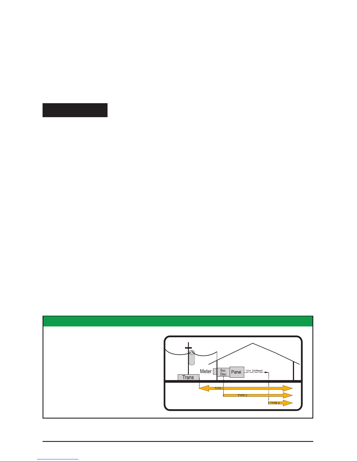
Type 1 SPD: Installation on the line side or load side of the service disconnect overcurrent device. Type
1 SPDs may be used in Type 2 installations. Examples: surge arrestors, lightning arrestors, meter hubs,
metering cabinets, ran out of breaker positions, etc.
Type 2 SPD: Downstream of service disconnect; probably will connect via breaker. Examples:
switchboards, power panels, panelboards, equipment, motors, pumps, etc.
Type 3 SPD: Point of Use SPD, sometimes plug-connected SPD.
Type 4 SPD: Has dierent contexts in UL 1449 and CSA 22.2 No. 269. Call for assistance.
FIGURE1: NEC® ARTICLE 285 & UL 14494
SPD Types: Types 1, 2, & 3
Based on Location within electrical
distribution system
(also coincides with ANSI/IEEE C62.41.2 -
2002 Categories C, B & A)
WARNING
 Loading...