

Page 1
SERIES 300
Dual Purpose Quick Connect Power Panels
800 – 4000 amp Pad Mount
Installation Manual
381333-488
2/2021
Page 2

SERIES 300 Quick Connect Power Panel Installation Manual
Table of Contents
Limited Warranty ...................................................................................................................................................... 3
Maintenance ............................................................................................................................................................. 3
Technical Support ..................................................................................................................................................... 3
Prior to Installation ................................................................................................................................................... 4
Shipment: Unpacking and Inspection ................................................................................................................ 4
Initial Installation ....................................................................................................................................................... 5
Step 1: Fasten ASCO SERIES 300 Dual Purpose Quick Connect Power Panel to secure base ............................ 5
Step 2: Installing the Conduit .................................................................................................................................... 5
Installation .................................................................................................................................................................. 6
Step 3: Wiring the Lug Terminals (ATS only) ........................................................................................................... 6
Step 4: Wiring the Lug Terminals (ATS & Permanent Generator) ........................................................................... 6
Step 5: Configuring the Phase Rotation Monitor ...................................................................................................... 7
Step 6: Determine Phase Rotation ........................................................................................................................... 7
Set-up -Portable Generator Connection (Lower Section) ............................................................................ 8
Step 7: Determining phase rotation of generator ..................................................................................................... 8
Step 8: Conduct a safety test to ensure proper installation ...................................................................................... 8
Step 9: Making Cam Connections ............................................................................................................................ 8
Step 10: Connect two wire auto start circuit ............................................................................................................. 9
Step 11: Close and lock lower chamber door, allowing cables to exit through smaller cable door ........................ 9
Step 12: Powering Up ............................................................................................................................................... 9
Step 13: Disconnection .......................................................................................................................................... 10
Step 14: Secure front door to complete .................................................................................................................. 10
Set-up Load Bank Connection Section (Upper Section) ............................................................................ 11
Step 15: Making Cam Connections ........................................................................................................................ 11
Step 16: Connecting Load Dump Circuit ............................................................................................................... 11
Step 17: Powering Up ............................................................................................................................................. 11
Step 18: Disconnection .......................................................................................................................................... 11
Trap Key Interlocks ................................................................................................................................................ 12
Standard Accessories ........................................................................................................................................... 13
Load Dump Receptacle .......................................................................................................................................... 13
Auto Start Terminals & Auto Start Destination Switch ........................................................................................... 13
Standard Accessory Wiring Diagram ..................................................................................................................... 13
Appendix A ............................................................................................................................................................... 14
Pre-Operation and Maintenance Checklist ............................................................................................................. 14
Index .......................................................................................................................................................................... 15
2 381333-488
Page 3
Installation SERIES 300 Quick Connect Power Panel
Limited Warranty
DANGER is used in this manual to warn of a
hazard situation which, if not avoided, will result
in death or serious injury.
WARNING is used in this manual to warn of a
hazardous situation which, if not avoided, could
result in death or serious injury.
CAUTION is used in this manual to warn of a
hazardous situation which, if not avoided, could
result in minor or moderate injury.
When this ASCO SERIES 300 Dual Purpose Quick
Connect Power Panel is installed and operated,
according to the manual instructions, ASCO Power
Technologies will repair or replace any of its
mechanical or electrical parts if they are found to be
defective in material or workmanship within two years
of the purchase date.
Maintenance
The ASCO SERIES 300 Dual Purpose Quick Connect
Power Panels will require maintenance. ASCO Power
Technologies recommends annual inspections to keep
the panel in safe operating condition. ASCO Power
Technologies recommends that the Pre-Operation and
Maintenance Checklist under Appendix A serve a basis
for annual inspection
Important
This manual contains information critical to proper
installation and operation of the ASCO SERIES 300
Dual Purpose Quick Connect Power Panels. Be certain
to read and understand all instructions prior to
installation and operation.
The ASCO SERIES 300 Dual Purpose Quick
Connect 800-4000A Pad Mount Power Panels are
not designed for simultaneous operation of both
input and output connections when the Power
Panels are connected to a permanent generator
and ATS via mechanical lugs. Castell or Kirby Key
locks must be installed on generation connection
door and permanent generator breaker which
serves as an interlock between permanent
generator and portable generator.
ASCO SERIES 300 Dual Purpose Quick Connect
Power Panels are ETL listed to UL891 Standards.
Technical Support
ASCO Power Services are available to assist in
resolving issues by calling 1-800-800-2726 (ASCO) or
by emailing powerwarranty@ascopower.com. For any
additional information, please refer to ascopower.com.
381333-488 3
Page 4
SERIES 300 Quick Connect Power Panel Installation Manual
Prior to Installation: Site Preparation
Prepare the installation site according to local codes
The ASCO SERIES 300 Dual Purpose Quick Connect
Power Panels are to be set on an exterior pad and
secured to a building or to the pad using 3/8” fasteners
(Figure 1).
The surface where the ASCO SERIES 300 Dual
Purpose Quick Connect Power Panel is to be secured
must be capable of supporting the weight of the cabinet
as well as the cable attached to it.
The following should be taken into consideration when
locating the ASCO SERIES 300 Dual Purpose Quick
Connect Power Panel:
– The ASCO SERIES 300 Dual Purpose Quick
Connect Power Panel is designed for exterior
operation ONLY.
– Identify and meet local codes and local Authority
Having Jurisdiction (AHJ)
– To prevent carbon monoxide poisoning from
improperly ventilated generator emissions, the
Power Panel must be mounted outdoors only. The
mounting location is to be carefully selected to
allow convenient connection to a generator and
located a suitable distance away from any building
openings or HVAC inlets.
Shipment: Unpacking and Inspection
Be careful in the use of sharp objects when cutting
packaging as damage to the outer enclosure may
result.
Perform a visual inspection to ensure the door and all
hasps are in functioning condition and that the panel
integrity is intact.
– Proper clearance must be allowed in front of the
ASCO SERIES 300 Dual Purpose Quick Connect
Power Panel to allow for opening of access doors
and attachment of externally connected cables.
This distance should be no less than six(6) feet
from the face of the panel.
– While lock protection is provided, access by
unauthorized personnel and vandals should be
taken into consideration when locating this device.
Secure with 3/8” fasteners
Figure 1. Bottom View
4 381333-488
Page 5
Installation SERIES 300 Quick Connect Power Panel
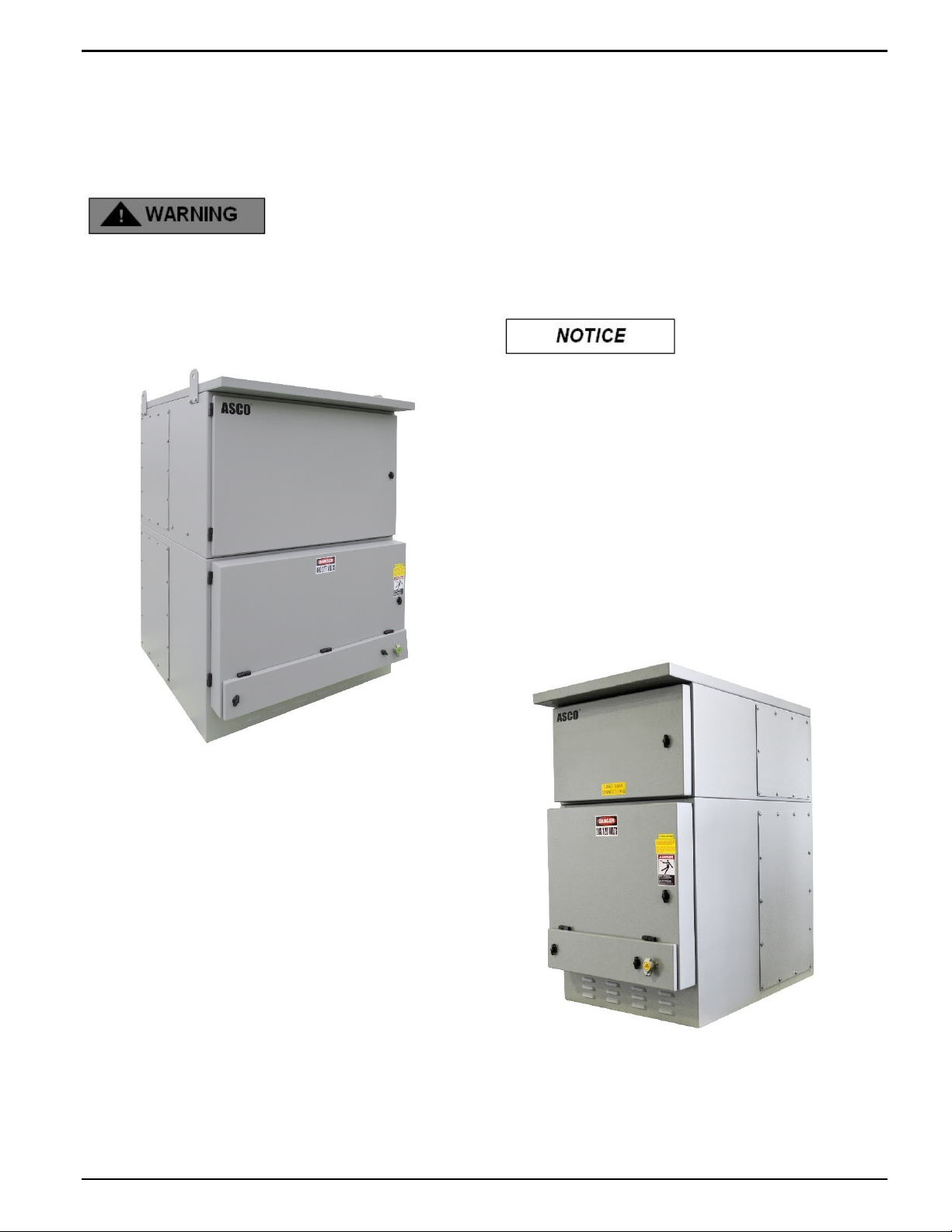
Initial Installation
The installation of the ASCO SERIES 300 Dual
Purpose Quick Connect Power Panel must be
done by qualified personnel in accordance
with local electrical codes.
ASCO SERIES 300 Dual Purpose Quick Connect
Power Panels are front heavy. Care must be taken
to secure the device when its lifted and moved.
Lifting eyes are provided on the enclosure to
assist with proper lifting and movement of
enclosures (Figure 2).
Step 1: Fasten the ASCO SERIES 300 Dual
Purpose Quick Connect Power Panel to
secure base.
1. Base must be level and plumb to allow for proper
drainage from the ASCO SERIES 300 Dual
Purpose Quick Connect Power Panel weep holes.
2. Fastening onto an external wall using 3/8”
fasteners must be completed prior to proceeding
with any terminations (see Figure 1 for hole
spacing).
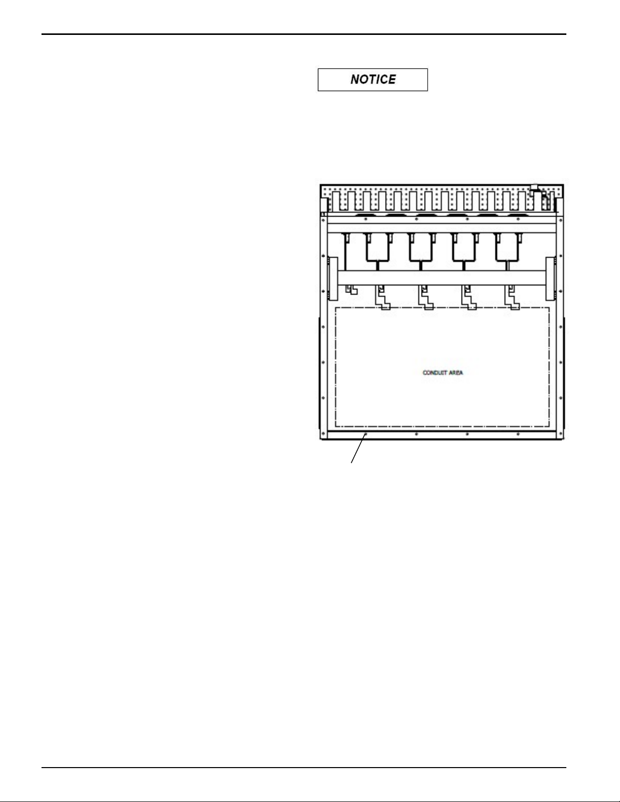
Step 2: Installing the Conduit
Conduit to enter through the bottom, rear and
sides unit (Figure 3).
To maintain TYPE 3R Rating compliance for the
enclosure, proper sealing procedures must be followed.
This is to include, but not limited to, the use of proper
gaskets.
1. Remove rear and side panels to expose
termination chamber.
Figure 2
2. Conduit to be sized according to cable rating.
3. It is recommended that a knockout punch be used
to cut hole for conduit.
4. Place the punch on the panel that was removed
from the enclosure and draw the punch through to
the die on the outside.
Figure 3
381333-488 5
Page 6

SERIES 300 Quick Connect Power Panel Installation Manual
Installation
Connecting to ATS ONLY
Step 3: Wiring the Lug Terminals
Ensure circuit breakers are OFF and the transfer
switch is locked out from utility power prior to
connection.
Failure to install transfer switch will create the
potential for the generator to energize utility lines
and endanger utility personnel. Conversely, utility
lines may energize the ASCO SERIES 300 Dual
Purpose Quick Connect Power Panel and
endanger generator personnel.
The ASCO SERIES 300 Dual Purpose Quick Connect
Power Panels consist of both recessed male 16 series
single pole connectors (inlets) and female single pole
connectors (outlets).
The ASCO SERIES 300 Dual Purpose Quick Connect
Power Panel inlet portion is for use only for connection
of a generator to the source terminals of a transfer
switch, such that the inlets are only energized from the
generator.
The ASCO SERIES 300 Dual Purpose Quick Connect
Power Panel outlet portion is used only for connection
of a load bank to the portable generator such that the
outlets are only energized from the portable generator.
1. Pull the cables from the transfer switch to the ASCO
SERIES 300 Quick Connect Power Panel
2. Beginning with the ground, strip and install the
cables in the appropriate mechanical lugs.
The mechanical lugs can accommodate 500 to
800 MCM, Copper or Aluminum wire.
3. Tighten mechanical lugs to 375 lb.-in torque each
4. If metallic conduit is used, connect ground wire from
ground bushing on conduit to the ground connection
point in the upper right quadrant of the panel
5. Ground conductor must be a minimum of #2 AWG
Connection to ATS & Permanent Generator
via mechanical lugs
Step 4: Wiring the Lug Terminals
The ASCO SERIES 300 Dual Purpose Quick
Connect Power Panels 800 – 4000A Pad Mount
Power Panels are not designed for simultaneous
operation of both input and output connections
when the Power Panel is connected to both a
permanent generator and ATS via mechanical
lugs. Castell or Kirk Key locks must be installed on
generator breaker which serves as an interlock
between permanent generator and portable
generator.
Ensure circuit breakers on the permanent
generator are OFF and the transfer switch is
locked out from utility power prior to connection.
Failure to install transfer switch will create the
potential for the generator to energize utility lines
and endanger utility personnel. Conversely, utility
lines may energize the ASCO SERIES 300 Dual
Purpose Quick Connect Power Panel and
endanger generator personnel.
The ASCO SERIES 300 Dual Purpose Quick Connect
Power Panels consist of both recessed male 16 series
single pole connectors (inlets) and female single pole
connectors (outlets).
1. Pull the cables for the transfer switch to the ASCO
SERIES 300 Quick Connect Power Panel
2. Beginning with the ground, strip and install the
cables in the appropriate mechanical lugs.
The mechanical lugs can accommodate 500 to
800 MCM, Copper or Aluminum wire.
3. Tighten mechanical lugs to 375 lb.-in torque each
4. If metallic conduit is used, connect ground wire from
ground bushing on conduit to the ground connection
point in the upper right quadrant of the panel
5. Ground conductor must be a minimum of #2 AWG
Conduit shall NOT be relied upon to provide
grounding protection to tap box
6. Continue to connect the neutral and then the
phases. (continue to page 6).
6 381333-488
Conduit shall NOT be relied upon to provide
grounding protection to tap box
Page 7

Installation SERIES 300 Quick Connect Power Panel
6. Continue to connect the neutral and then the
phases
7. Repeat steps 1-6 for cable connection from
permanent generator to mechanical lugs of ASCO
SERIES 300 Quick Connect Power Panel
8. Ensure that Castell K-lock (provided with unit) is
installed on the permanent generator breaker.
Three phase power systems consist of three
phase or hot conductors that are shifted by 120
degrees. Three phase loads such as motors may
only work properly if the phases are connected in
the correct order. Some motors may work when
connected improperly but will operator backwards.
Utility power and electrical generators may be
wired either in a clockwise or counterclockwise
order. It is important that any generator connected
to the ASCO SERIES 300 Dual Purpose Quick
Connect Power Panel is connected in the same
rotation (clockwise or counterclockwise) as the
utility power
Step 6: Determine Phase Rotation
This information will be needed when connecting a
generator.
1. Determine phase rotation of the utility power.
2. Connect a phase rotation meter to a three phase
power source in the building and record whether the
building is wired clockwise or counterclockwise
3. Apply the provided label to the inside of the ASCO
SERIES 300 Dual Purpose Quick Connect Power
Panel on the inside of the cam connection chamber
box door (Figure 6).
4. Should the phase rotation monitor configuration and
utility power (label found on the inside of the door for
the Cam connection chamber) match, proceed to
Step 7.
5. Should the phase rotation monitor configuration and
the utility power (label found on the inside of the door
for the Cam connection chamber) differ, swap the A
and B phase rotation connection wires at the
camlock connection so it matches utility power and is
consistent with the label found inside the door.
Step 5: Configuring the Phase Rotation
Monitor
A phase rotation monitor comes standard on all ASCO
SERIES 300 Dual Purpose Quick Connect Power
Panels (Figure 4). The Phase Rotation Monitor is
prewired from the factory for ABC rotation (Figure 5)
Figure 4
Place rotation label here
Figure 6
Figure 5
381333-488 7
Page 8

SERIES 300 Quick Connect Power Panel Installation Manual
Set-up – Portable Generator
Connection (Lower Section)
The ASCO SERIES 300 Dual Purpose Quick
Connect Power Panels consist of both recessed
male 16 series single pole connectors (inlets) and
female single pole connectors (outlets). The
portable generator connectors are in the lower
compartment of the enclosure.
DO NOT ATTEMPT CONNECTION WHILE
CIRCUITS ARE LIVE
– Do not use cables if they appear frayed
– Do not use cable if connectors or plug do not seat
properly
– Do not use cables if any copper cabling is exposed
– To limit risk of shock, disable generator automatic
start to prevent unintended starting
Step 7: Determining Phase Rotation of
generator
1. Disconnect generator from all loads if needed
2. Connect a phase rotation meter to the output
phases of the generator
3. Record generator phase rotation (clockwise or
counterclockwise)
Proper Connection (Figure 7)
A. Grasp connection jacket and firmly insert cam
connector into cam plug
B. Push on cam connector jacket until connector fully
seats in the cam plug
C. Rotate cam connector jacket counterclockwise until
it stops
Figure 7
Step 9: Making Cam Connections
1. Open main chamber door.
2. Continue with connections, beginning with the rear
of the cabinet and working forward.
3. Complete ALL Ground connections working from
back to front prior to proceeding
4. Complete the Neutral (white) connections,
beginning with the furthest from the front door
Step 8: Conduct a safety test to ensure
proper installation
1. Do not attempt to use the ASCO SERIES 300 Dual
Purpose Quick Connect Power Panel prior to
installation and completing the Pre-Operation and
Maintenance Checklist under Appendix A.
2. Open lower chamber door.
3. Complete the Ground (green) connections,
beginning with the furthest from the front door to the
left
8 381333-488
Page 9

Installation SERIES 300 Quick Connect Power Panel
Proper Connection (Figure 7)
A. Grasp connection jacket and firmly insert cam
connector into cam plug
B. Push on cam connector jacket until connector fully
seats in the cam plug
C. Rotate cam connector jacket counterclockwise until
it stops
D. Continue with connections, beginning with the rear
of the cabinet and working forward.
E. Complete the Phase (hot) connections
i. Should the phase rotation of the generator (as
determined in Step 5 above) and utility power
(label found on the inside of the door for the
Cam connection chamber) match, connect the
Hots as follows:
Generator Hot ASCO SERIES 300 Quick
Connect Power Panel Hot
A A
B B
C C
Step 10: Connect Two wire auto start
circuit
1. Connect 2 wire auto start circuit from transfer switch
to terminal post located in the upper right corner of
the Quick Connect Panel (Figure 8).
2. Connect the 2 wire auto start circuit from the
generator to terminal post.
Figure 8
Step 11: Close and lock lower chamber
door, allowing cables to exit through
smaller cable door
Step 12: Powering Up
ii. Should the phase rotation of the generator (as
determined in Step 7.3 above) and utility power
(label found on the inside of the door for the
Cam connection chamber) NOT match, connect
the Hots as follows:
Generator Hot ASCO SERIES 300 Quick
Connect Power Panel Hot
A B
B A
C C
Proper Connection (Figure 7)
A. Grasp connection jacket and firmly insert cam
connector into cam plug
B. Push on cam connector jacket until connector fully
seats in the cam plug
C. Rotate cam connector jacket counterclockwise until
it stops
5. Continue with connections, beginning with the rear
of the cabinet and working forward.
6. Complete ALL Phase connections working back to
front prior to proceeding
Power MUST BE supplied from single generator
1. Start generator per manufacturer instructions.
7. Make sure all connections are right and secure
381333-488 9
Page 10

SERIES 300 Quick Connect Power Panel Installation Manual
Step 13: Disconnection
DO NOT ATTEMPT CONNECTION WHILE
CIRCUITS ARE LIVE
1. To limit risk of shock, disable generator automatic
start to prevent unintended starting:
– Open lower chamber door
– Order of disconnect
2. Disconnect the Phase (hot) connections, beginning
with close to the front door to the right.
Proper Connection (Figure 9)
A. Grasp connector jacket firmly and rotate cam
connector clockwise until it stops
B. Firmly pull on connector until it separates from the
plug
C. Set aside
3. Continue with ALL Phase (hot) connections,
beginning with the front of the cabinet and working
from front to back.
7. Complete disconnect of ALL Neutral connections
prior to proceeding. Disconnect the Ground (green)
connections, beginning with the closest to front
door.
Proper Disconnection (Figure 9)
A. Grasp connector jacket firmly and rotate cam
connector clockwise until it stops
B. Firmly pull on connector until it separates from the
plug
C. Set aside
8. Continue with ALL Ground (green) connections,
beginning with the front of the cabinet and working
rearward.
9. Complete disconnect of ALL Neutral connections
prior to proceeding
Step 14: Secure front door to complete.
Set-up – Load Bank Connection
(Upper Section)
The ASCO SERIES 300 Dual Purpose Quick
Connect Power Panels consist of both recessed
male 16 series single pole connectors (inlets) and
female single pole connectors (outlets). The load
bank connectors are in the upper compartment of
the enclosure.
Figure 9
4. Complete disconnect of ALL hot connections prior
to proceeding.
5. Disconnect the Neutral (white) connection,
beginning with closest to the front door.
Proper Disconnection (Figure 9)
A. Grasp connector jacket firmly and rotate cam
connector clockwise until it stops
B. Firmly pull on connector until it separates from the
plug
C. Set aside
6. Continue with ALL Neutral (white) connections,
beginning with the front of the cabinet and working
from front to back.
Dual Purpose Quick Connect Panel
Enclosure door must remain open while
load bank is connected.
DO NOT ATTEMPT CONNECTION WHILE
CIRCUITS ARE LIVE
– Do not use cables if they appear frayed
– Do not use cable if connectors or plug do not seat
properly
– Do not use cables if any copper cabling is exposed
– To limit risk of shock, disable generator automatic
start to prevent unintended starting
10 381333-488
Page 11

Installation SERIES 300 Quick Connect Power Panel
Step 15: Making Cam Connections
1. Open upper chamber door.
2. Complete the Ground (green) connections,
beginning with the furthest from the front door to the
left.
Proper Connection (Figure 10)
A. Grasp connection jacket and firmly insert cam
connector into cam plug
B. Push on cam connector jacket until connector fully
seats in the cam plug
C. Rotate cam connector jacket counterclockwise until
it stops.
Step 16: Connecting Load Dump Circuit
1. Connect Load Dump cable to L1-15 receptable if
required.
Step 17: Powering Up
Power MUST BE supplied from a source wired to a
Transfer Switch
1. Toggle the transfer switch, diverting power from
building loads to load bank.
Figure 10
3. Continue with connections, beginning with the rear
of the cabinet and working forward
4. Complete ALL Ground connections working from
back to front prior to proceeding
5. Continue with connections, beginning with the rear
of the cabinet and working forward.
6. Complete the Phase (hot) connections.
Proper Disconnection (Figure 10)
A. Grasp connection jacket and firmly insert cam
connector into cam plug
B. Push on cam connector jacket until connector fully
seats in the cam plug
C. Rotate cam connector jacket counterclockwise until
it stops.
381333-488 11
Page 12

SERIES 300 Quick Connect Power Panel Installation Manual
Trap Key Interlocks
The ASCO SERIES 300 Dual Purpose Quick Connect
Power Panels come with a Castell Type D lock with a
flip cap mounted to the trap door of the lower
compartment housing the portable generator
connections. This is shown in Figures 12 and 13. This
lock is required for applications where the Power Panel
is connected to both a permanent generator and
automatic transfer switch via mechanical lugs
Figure 12
The ASCO SERIES 300 Dual Purpose Quick Connect
Power Panels come with a Castell K Bolt interlock
inside of the enclosure to be mounted at the breaker of
the permanent generator. To install this lock, mount the
lock at the breaker so that the bolt is fully extended and
prohibits the breaker from operation.
Castell Type K Bolt interlock Operation
1. While the bolt is extended, the key is free and
mechanism is locked.
2. By inserting and turning the key, you can retract the
bolt. This will trap the key into the lock.
Figure 13
Castell Type D lock Operation
1. While the catch is trapped, the key is free. The
mechanism is locked keeping the door lock closed.
2. By inserting and turning the key in the D lock, you
can release the catch. This will trap the key in the
lock.
3. The Key remains trapped while the catch is
released and the door is open.
3. The key stays trapped while the bolt is retracted.
K-Lok Bolt Installation
While the bolt is completely retracted, cut of the
excess portion of the bolt that would prevent the
breaker from operating while the key is captive.
12 381333-488
Page 13

Installation SERIES 300 Quick Connect Power Panel
Standard Accessories
Load Dump Receptacle
The ASCO SERIES 300 Dual Purpose Quick Connect
Power Panels come with an L1-15 Twist Lock
Receptacle standard to be used to connect a Load
Bank Load Dump circuit (Figure 14). This receptacle is
rated for 15A 125V and is prewired to the load dump
terminal block located inside of the enclosure.
Figure 14-Load Dump Receptable
Auto Start Terminals & Auto Start
Destination Switch
Standard Accessory Wiring Diagram
The Load Dump receptacle and Auto Start Destination
switch is prewired to two separate terminal blocks as
shown in Figure 16. Permanent Generator auto start
wiring, and ATS engine start wiring are landed at the
terminal block in the enclosure. Portable generator auto
start wiring is landed at the banana terminal post
located at the front of the enclosure. Figure 17 shows
the terminal block mounted inside of the enclosure.
The ASCO SERIES 300 Dual Purpose Quick Connect
Power Panels come with red & black banana binding
terminal post standard for easy connection of a two-wire
engine start circuit from the generator (Figure 15).
These binding posts are prewired internally to an Auto
Start Destination toggle switch (Figure 15) which allows
the user to select which generator the ATS will start
when the engine start signal is sent from the ATS.
Figure 16
Figure 15- Portable Gen Auto Start Terminals &
Auto Start Destination Switch
Figure 17
381333-488 13
Page 14

SERIES 300 Quick Connect Power Panel Installation Manual
Appendix A
Pre-Operation Checklist
1. Visual inspection of the enclosure:
– Ensure the ASCO SERIES 300 Dual Purpose Quick
Connect Power Panel is firmly secured to its base
and/or building
– Review conduit connection for signs of leakage
– Ensure pain is intact with no signs of rust or
corrosion
2. Open main chamber door and remove side panels:
– Ensure unit is dry and free of debris
– Ensure that gaskets are pliable and no cracking
exists
– Ensure that door hinges are secure and lubricated
– Ensure that keylocks are intact and operational
– Ensure that all load terminals are securely fastened
and that the bolts are set at 98 foot pounds of
torque
– Ensure paint is intact with no signs of rusting or
corrosion
– Ensure electrical connections are intact with no
signs of corrosion or cracking
3. Review all safety labels and ensure that they are
present and legible:
– Replace as needed
4. Inspect all portable cables:
– Do not use cables if they appear frayed
– Do not use cables if connectors or plugs do not seat
properly
– Do not use cables if any copper wiring is exposed
5. ASCO Power Services are available to assist in
resolving issues. If you have any questions or need
technical advice or suggestions regarding this
product, please contact ASCO Power Technologies
at 1-800-800-2726(ASCO) or email
powerwarranty@ascopower.com
14 381333-488
Page 15

Index Operator’s Manual
INDEX
A
annual inspection 3
auto start circuit 9
auto start destination switch 13
auto start terminals 13
C
cam connections 8.10
chamber door 8, 9, 10, 11
circuit breakers 6
conduit 5, 6, 14
installing, 5
copper wiring 14
D
disconnection 9, 11
G
H
Help 3, 14
1-800–800–ASCO (2726)
powerwarranty@ascopower.com
hot conductors 7
I
inspection 3, 4, 14
L
limited warranty 3
load bank 10
load circuit dump 10
load dump receptable 13
lugs 6
M
maintenance 3, 8
S
safety test 8
safety labels 14
secure base 5
site preparation 4
shipment 4
T
technical support 3
terminals 6, 13, 14
torque 6, 14
trap key 12
U
unpacking 4
V
visual inspection 4, 14
gasket 5, 14
generator 8
P
phase rotation 7, 8
monitor, 7
plug 10, 11, 14
portable cables 14
powering up 9, 10
pre-operation checklist 14
W
wiring 6
381333-488 15
Page 16

Installation Manual SERIES 300 Quick Connect Power Panel
Printed in U.S.A
ASCO Power Technologies
160 Park Avenue
Florham Park, NJ 07932-1591 USA
Phone: 1 800 800-2726 (ASCO) for sales or service
www.ascopower.com
©2021 ASCO Power Technologies. All Rights Reserved
16 381333-488
 Loading...