

Page 1

IntraCore® 3724PWR
24-Port FastEthernet/12 Ports PoE + 2 Gigabit Combo
L2+ Management Switch
User’s Manual
Page 2

IntraCore 3724PWR
24-Port FastEthernet/12 Ports PoE + 2 Gigabit Combo
L2+ Management Switch
User’s Manual
Asante
47709 Fremont Blvd
Fremont, CA 94538
USA
SALES
408-435-8388
TECHNICAL SUPPORT
408-435-8388: Worldwide
www.asante.com/support
support@asante.com
Copyright © 2008 Asante. All rights reserved. No part of this document, or any associated artwork, product design, or
design concept may be copied or reproduced in whole or in part by any means without the express written consent of
Asante. Asante and IntraCore are registered trademarks and the Asante logo, AsanteCare, Auto-Uplink, and
IntraCare are trademarks of Asante. All other brand names or product names are trademarks or registered
trademarks of their respective holders. All features and specifications are subject to change without prior notice.
Draft D 9/18/08
2 Asante IC3724PWR User’s Manual
Page 3

Table of Contents
IntraCore 3724PWR...............................................................................................................2
Chapter 1 Introduction…………………………………………………………………………………………………………….7
1.1 Features...................................................................................................................................................................7
1.2 System Defaults.......................................................................................................................................................8
1.3 Package Contents..................................................................................................................................................11
1.4 Front and Back Panel Descriptions........................................................................................................................11
1.4.1 LEDs............................................................................................................................................................13
1.5 Management and Configuration.............................................................................................................................13
1.5.1 Console Interface.........................................................................................................................................13
Chapter 2: Hardware Installation and Setup ................................................................................................................14
2.1 Installation Overview..............................................................................................................................................14
2.1.1 Safety Overview...........................................................................................................................................14
2.1.2 Recommended Installation Tools.................................................................................................................15
2.1.3 Power Requirements....................................................................................................................................15
2.1.4 Environmental Requirements.......................................................................................................................15
2.1.5 Cooling and Airflow......................................................................................................................................15
2.2 Installing into an Equipment Rack..........................................................................................................................15
2.2.1 Equipment Rack Guidelines.........................................................................................................................16
2.3 SFP Mini GBIC Ports .............................................................................................................................................16
2.4 Connecting Power..................................................................................................................................................17
2.5 Connecting to the Network.....................................................................................................................................17
2.5.1 10/100/1000BaseT Ports Cabling Procedures.............................................................................................17
2.5.2 Gigabit Ethernet Ports Cabling Procedures .................................................................................................18
Chapter 3: Initial Software Setup..................................................................................................................................20
3.1 Connecting to a Console........................................................................................................................................20
3 Asante IC3724PWR User’s Manual
Page 4

3.2 Connecting to a PC................................................................................................................................................22
3.3 Username and Password................................................................................................................................22
3.5 Restoring Factory Defaults.....................................................................................................................................23
Chapter 4: Understanding the Command Line Interface (CLI).....................................................................................24
4.1 User Top (User EXEC) Mode.................................................................................................................................24
4.2 Privileged Top (Privileged EXEC) Mode ................................................................................................................25
4.3 Global Configuration Mode.....................................................................................................................................27
4.3.1 Interface Configuration Mode.......................................................................................................................28
4.4 Advanced Features Supported within the Command Mode...................................................................................29
4.5 Using CLI Command History..................................................................................................................................31
4.6 Using Command-Line Editing Features and Shortcuts ..........................................................................................32
4.6.1 Moving Around on the Command Line.........................................................................................................32
4.6.2 Completing a Partial Command Name.........................................................................................................33
4.6.3 Deleting Entries............................................................................................................................................33
Chapter 5:
5.1 Managing the System ............................................................................................................................................34
5.2 Managing Configuration Files.................................................................................................................................36
Managing the System and Configuration Files …………………………………………………………………34
5.1.1 Setting the System Clock.............................................................................................................................34
5.1.2 Specify the Hostname..................................................................................................................................35
5.1.5 Test Connections with Ping Tests................................................................................................................ 35
5.1.3 Enable the System Log................................................................................................................................35
5.1.4 Displaying the Operating Configuration........................................................................................................35
5.2.1 Configuring from the Terminal......................................................................................................................36
5.2.2 Copying Configuration Files to a Network Server ........................................................................................36
5.2.3 Copying Configuration Files from a Network Server to the Switch...............................................................37
5.3 Managing system image Files................................................................................................................................38
5.3.1 Saving System image to a Network Server..................................................................................................38
5.3.2 Replacing System image from a Network Server........................................................................................38
5.4 Configuring SNMP .................................................................................................................................................38
5.4.1 Configuring SNMP Support..........................................................................................................................39
4 Asante IC3724PWR User’s Manual
Page 5

5.5 Spanning Tree Algorithm .......................................................................................................................................40
5.5.1 Spanning Tree Parameters..........................................................................................................................40
5.5.2 Rapid Spanning Tree Protocol (RSTP) ........................................................................................................41
5.5.3 Configuring spanning-tree............................................................................................................................42
Chapter 6: Configuring IP.............................................................................................................................................46
6.1 Establish Address Resolution.................................................................................................................................47
6.2 Managing IP Multicast Traffic.................................................................................................................................48
6.2.1 IGMP Overview............................................................................................................................................48
6.2.2 Configuring IGMP ........................................................................................................................................48
6.3 Access Lists..........................................................................................................................................................50
6.3.1 Creating an Access List ...............................................................................................................................50
6.3.2 Configuring an Access List...........................................................................................................................50
6.3.3 Applying an Access List to an Interface .......................................................................................................52
6.3.4 Enabling an Access List...............................................................................................................................52
Chapter 7: Power over Ethernet (PoE)........................................................................................................................53
7.1 PoE Definitions……………………………………………………………………………………………………………….53
7.2 PoE Show Example ………………………...……………………………………………………………………...……...55
7.2 PoE Interface Settings Example …………………………………………………………………………….……… .57
Chapter 8: VLAN Configuration....................................................................................................................................58
8.1 Creating or Modifying a VLAN................................................................................................................................58
8.2 VLAN Port Membership .........................................................................................................................................59
8.2.1 configuring vlan ports...................................................................................................................................59
8.2.2 Trunk (IEEE 802.1q) ....................................................................................................................................60
Chapter 9:
9.1 Scheduling algorithm ..............................................................................................................................................62
Quality of Service Configuration ………………………………………………………………………………….60
9.1.1 Configuring Weighted Round Robin.............................................................................................................62
9.1.2 Monitoring Weighted Round Robin ..............................................................................................................63
9.2 Priority Queuing .....................................................................................................................................................63
5 Asante IC3724PWR User’s Manual
Page 6

9.2.1 Priority Mapping...........................................................................................................................................63
9.2.2 Port Based QOS..........................................................................................................................................64
9.2.3 802.1P Based QOS......................................................................................................................................64
9.2.4 IP Based QOS .............................................................................................................................................64
9.3 Traffic Shaping.......................................................................................................................................................65
9.3.1 Configuring Traffic Shaping for an Interface.................................................................................................65
9.4 Rate Limiting..........................................................................................................................................................65
Chapter 10: Configuring the Switch Using the GUI......................................................................................................66
10.1 Main Configuration Menu.....................................................................................................................................67
10.2 System.................................................................................................................................................................68
10.3 Ports .……………………………………….………………………………………………………………………………72
10.3.1 Power over Ethernet (PoE) ……………………………………………………………………………………………..77
Chapter 11: CLI Commands ......................................................................................................................................118
Appendix A: Basic Troubleshooting ...........................................................................................................................148
Appendix B: Specifications ……………………………………………………………………………………………………148
Appendix C: FCC Compliance and Warranty Statements..........................................................................................150
C.1 FCC Compliance Statement.........................................................................................................................150
C.2 Important Safety Instructions........................................................................................................................150
C.3 IntraCore Warranty Statement......................................................................................................................151
Index …………………………………………………………………………………………………………………………….152
6 Asante IC3724PWR User’s Manual
Page 7

Chapter 1: Power over Ethernet (PoE)
The IntraCore IC3724PWR 24-port + 2 Gigabit Layer 2+ Managed Switch is a high-perfor m ance network switch used
to reduce network congestion and application response times. The 24-port IntraCore IC3724PWR multi-protocol
switch supports Layer 2+ and Ethernet switching. The switch has 24 10/100BaseT ports with Auto-Uplink and has 2
combination ports used for sharing with SFP mini GBICs. Fiber technology is used to connect two switches together.
The switches also have an SNMP-based management agent embedded on the main board. This agent supports both
in-band and out-of-band access for managing the switch.
These switches have a broad range of features for Layer 2+ switching delivering reli ability and consistent
performance for network traffic. The switches improve network performance by segregating them into separate
broadcast domains with IEEE 802.1Q compliant VLANs and provide multimedia applications with multicast switching
and CoS services.
The system can operate as a stand-alone network or be used in combination with other IntraCore switches in the
backbone.
1.1 Features
The IntraCore IC3724PWR Ethernet switch is a 24-port Layer 2+ multi-media, multi-protocol (Ethernet and Layer 2+)
switch. The following is a list of features:
• 24 port 10/100 switch with auto-uplink
• 2 port gigabit combo ports
• Supports wire-speed L2+ switching
• CoS provisioning on Layers 2 and 802.1p, IP precedence (TOS, DSCP )
• Packet filtering
• 8K MAC address
• Up to 255 configurable 802.1Q based VLAN groups
• Up to 256 multicast groups, statically created or dynamically created by IGMP snooping
• SNMP v1, v2, and RMON, statistics counters supported
• Spanning Tree Protocol 802.1D (standard), 32 instances of 802.1w (rapid) VLAN and 802.1s (multiple)
• 6 trunks and 8 ports/trunk link aggregation
• 4 MB internal packet buffer
• Support for Jumbo Frames (up to 9 KB in length)
7 Asante IC3724PWR User’s Manual
Page 8

1.2 System Defaults
The system defaults are the configuration parameters set in the factory. Use command ‘Clear config’ to restore the
defaults followed by a ‘save’ command.
The following table lists some of the basic system defaults.
Function Parameter Default
Console Port Connection Baud Rate
Data bits
Stop bits
Parity
Local Console Timeout
Authentication login
Enable Privileged Exec from Normal Exec
Level
RADIUS Authentication
TACACS Authentication
802.1x Port Authentication
HTTPS
Port Security
IP Filtering
Auto
8
1
none
300 seconds
Username “admin”
Password “Asante”
Username “admin”
Password “Asante”
Disabled
Disabled
Disabled
Disabled
Disabled
Disabled
Web Management HTTP Server
HTTP Port Number
HTTP Secure Server
HTTP Secure Port Number
SNMP Community Strings
Traps
Port Configuration Admin Status
Auto-negotiation
8 Asante IC3724PWR User’s Manual
Enabled
80
Disabled
443
“public” (read only)
“private” (read/write)
Authentication traps: enabled
Link-up-down events:
enabled
Enabled
Enabled
Page 9

Flow Control
Port Capability
POE ports configuration Admin Status
Power Management Mode
Power Allocation
Disabled
1000BASE-T –
10 Mbps half duplex
10 Mbps full duplex
100 Mbps half duplex
100 Mbps full duplex
1000 Mbps full duplex
Full-duplex flow control
disabled
Symmetric flow control
disabled
1000BASE-SX/LX/LH –
1000 Mbps full duplex
Full-duplex flow control
disabled
Symmetric flow control
disabled
Enabled
Dynamic without priority
15400 miliwatts
Detection Type
IEEE 802.3af 4-Point
Detection only
Rate Limiting Input and Output Limits Disabled
Port Trucking LACP (all ports) Disabled
Broadcast Storm Protection Status
Broadcast Limit Rate
Spanning Tree Protocol Status
Address Table Aging Time
Virtual LANs Default VLAN
PVID
Acceptable Frame Type
Ingress Filtering
Switchport Mode (egress mode)
Enabled (all ports)
500 packets per second
Disabled
300 seconds
1
1
All
Disabled
untagged frames
9 Asante IC3724PWR User’s Manual
Page 10

Traffic Prioritization Ingress Port Priority
Weighted Round Robin
IP Precedence Priority
IP DSCP Priority
IP Settings IP Address
Subnet Mask
Default Gateway
DHCP
ARP
Multicast Filtering IGMP Snooping
0
Queue: 1 2 3 4
Weight: 1 2 4 8
Disabled
Disabled
192.168.0.1
255.255.255.0
0.0.0.0
Client: Disabled
Enabled
Disabled
System Log Remote logging
Memory-log
Flash-log
SNTP Clock Synchronization Disabled
Disabled
Enabled
Enabled
10 Asante IC3724PWR User’s Manual
Page 11

p
1.3 Package Contents
The following items are included in the switch’s package:
• Switch
• AC power cord
• RS232 straight-through serial cable for management console port
• Rack mount brackets with screws
• IntraCore IC3724PWR CD-ROM
Contact your dealer immediately if any of these items is missing.
1.4 Front and Back Panel Descriptions
The following section describes the front and back panels of the IntraCore IC3724PWR Series s witches.
The front panel of the IntraCore IC3724PWR contains the following: power and port LEDs, 24 10/100BaseT ports,
and 2 dual-function Gigabit ports that support either 1000BaseT or mini GBIC Gigabit Ethernet ports. The console
port may be front or back depending on model. For information on LEDs refer to the following section in this chapter.
3724PWR Front Panel
Ethernet
orts
Mini GBIC ports
3724PWR Rear Panel
11 Asante IC3724PWR User’s Manual
Page 12

12 Asante IC3724PWR User’s Manual
Page 13

1.4.1 LEDs
The IC3724PWR front panel LED display allows you to monitor the status of the switch.
The IC3724PWR has one power LED indicator. There are also LED indicators for each of the ports. Refer to the
following table for LED information.
LED Color Description
Power Green
Off
1000MBps Amber
Off
POE Amber
Off
Link/Activity Green
Blinking Green
Off
Power is on.
Power is off, or main power has failed.
A valid 1000 Mbps link has been established on the port.
No link has been established on the port or if Link/Activity led is on, the speed is either
100 or 10 Mbps.
A POE device is connected to the port and drawing power.
No POE device is connected to the port, no power is being drawn.
A link has been established on the port.
Activity has been detected.
No link has been established on the port.
1.5 Management and Configuration
The switch is managed using Command Line Interface (CLI) in order to access several different command modes.
Entering a question mark (?) at each command mode’s prompt provides a list of commands.
1.5.1 Console Interface
Support for local, out-of-band management is delivered through a terminal or modem attached to the EIA/TIA-232
interface. You can access the switch by connecting a PC or terminal to the console port of the switch, via a serial
cable. The default uername/ password set on the console line is admin/Asante (it is case-sensitive). The default IP
address is 192.168.0.1. It can be modified to suit your network setup. See 3.4 for details.
Remote in-band management is available through Simple Network Management Protocol (SNMP) and Teln et client.
When connecting via a Telnet session, the default login/password is also admin/Asante (case-sensitive).
See Chapter 2 for more information on connecting to the switch.
13 Asante IC3724PWR User’s Manual
Page 14

Chapter 2: Hardware Installation and Setup
Use the following guidelines to easily install the switch, ensuring that it has the proper power sup pl y and environment.
2.1 Installation Overview
Follow these steps to install the IntraCore IC3724PWR switch:
1. Open the box and check the contents. See Chapter 1.2 Package Contents for a complete list of the items
included with the IntraCore IC3724PWR switch.
2. Install the switch in an equipment or wall rack, or prepare it for desktop placement.
3. Connect the power cord to the switch and to an appropriate power source.
4. Connect network devices to the switch.
See the sections below for more detailed installation instructions.
2.1.1 Safety Overview
The following information provides safety guidelines to ensure your safety and to protect the switch from damage.
Note: This information is a guideline, and may not include every possible hazard. Use caution when installing this
switch.
• Only trained and qualified personnel should be allowed to install or replace this equipment
• Always use caution when lifting heavy equipment
• Keep the switch clean
• Keep tools and components off the floor and away from foot traffic
• Avoid wearing rings or chains (or other jewelry) that can get caught in the switch. Metal objects can heat up and
cause serious injury to persons and damage to the equipment.
• Avoid wearing loose clothing (such as ties or loose sleeves) when working around the switch
When working with electricity, follow these guidelines:
• Disconnect all external cables before installing or removing the cover
• Do not work alone when working with electricity
• Always check that the cord has been disconnected from the outlet before performing hardware configuration
14 Asante IC3724PWR User’s Manual
Page 15

• Do not tamper with the equipment. Doing so could void the warranty
• Examine the work area for potential hazards (such as wet floors or ungrounded cables)
2.1.2 Recommended Installation Tools
You need the following additional tools and equipment to install the switch into an equipment rack:
• Flat head screwdriver
• Phillips head screwdriver
• Antistatic mat or foam
2.1.3 Power Requirements
The electrical outlet should be properly grounded, located near the switch and be easily accessible. Make sure the
power source adheres to the following guidelines:
• Power: Auto Switching AC, 90-240 VAC
• Frequency range: 50/60 Hz
2.1.4 Environmental Requirements
Install the switch in a clean, dry, dust-free area with adequate air circulation to maintain the following environmental
limits:
• Operating Temperature: 0° to 40°C (32° to 104°F)
• Relative Humidity: 5% to 95% non-condensing
Avoid direct sunlight, heat sources, or areas with high levels of electromagnetic interference. Failure to observe these
limits may cause damage to the switch and void the warranty.
2.1.5 Cooling and Airflow
The IntraCore IC3724PWR switch uses internal fans for air-cooling. Do not restrict airflow by covering or obstructing
air vents on the sides of the switch.
2.2 Installing into an Equipment Rack
Important: Before continuing, disconnect all cables from the switch.
To mount the switch into an equipment rack:
15 Asante IC3724PWR User’s Manual
Page 16

1. Place the switch on a flat, stable surface.
2. Locate a rack-mounting bracket (supplied) and place it over the mounting holes on one side of the switch.
3. Use the screws (supplied) to secure the bracket (with a Phillips screwdriver).
4. Repeat the two previous steps on the other side of the switch.
5. Place the switch in the equipment rack.
6. Secure the switch by securing its mounting brackets onto the equipment rack with the appropriate screws
(supplied).
Important: Make sure the switch is supported until all the mounting screws for each bracket are secured to the
equipment rack. Failure to do so could cause the switch to fall, which may result in personal injury or damage to the
switch.
2.2.1 Equipment Rack Guidelines
Use the following guidelines to ensure that the switch will fit safely within the equipment rack:
• Size: 17.5 x 12.7 x 1.8 inches (440 x 234 x 45 mm)
• Ventilation: Ensure that the rack is installed in a room in which the temperature remains below 104° F (40° C). Be
sure that no obstructions, such as other equipment or cables, block airflow to or from the vents of the switch
• Clearance: In addition to providing clearance for ventilation, ensure that adequate clearance for servicing the
switch from the front exists
2.3 SFP Mini GBIC Ports
The GBIC Interface is the industry standard for Gigabit Ethernet Interfaces.
The Gigabit SFP module inserts into the Mini GBIC port to create a new Gigabit port. The hot-swapping feature on
the IntraCore IC3724PWR lets you install and replace the SFP transceivers while the system is operating; you do not
need to disable the software or shut down the system power.
To install the module, do the following:
1. Insert the transceiver with the optical connector facing out ward and the slot connector facing down. The module
is keyed to help establish the correct position.
2. Slide the SFP transceiver into the slot until it clicks into place.
3. Remove the module’s rubber port cap.
4. Connect the cable to the Gigabit SFP module’s port.
Caution: When replacing a SFP transceiver you must always disconnect the network cable before removing a
transceiver.
16 Asante IC3724PWR User’s Manual
Page 17

2.4 Connecting Power
Important: Carefully review the power requirements (Chapter 2.1.3) before connecting power to the switch.
Use the following procedure to connect power to the switch:
• Plug one end of the supplied power cord into the power connector on the back of the switch.
• Plug the other end into a grounded AC outlet.
The power LED show the initialization is in process. The front panel LEDs blink and the power LED illuminates when
it has initialized. The switch is ready for connection to the network.
Important: If the power does not come on, check the next section to ensure that the correct cabling is used.
2.5 Connecting to the Network
The switch can connect to an Ethernet network with the switch turned on or off. Use the following procedure to make
the network connections:
• Connect the network devices to the switch, following the cable guidelines outlined below.
• After the switch is connected to the network, it can be configured for management capabilities (see the
following chapters for information on configuration).
2.5.1 10/100/1000BaseT Ports Cabling Procedures
The 10/100/1000 ports on the switch allow for the connection of 10BaseT, 100BaseTX, or 1000BaseT network
devices. The ports are compatible with IEEE 802.3 and 802.3u standards.
Important: The switch must be located within 100 meters of its attached 10BaseT or 100BaseTX devices.
Use the following guidelines to determine the cabling requirements for the network devices:
• Connecting to Network Station: Category 5 UTP (Unshielded Twisted-Pair) straight-through cable (100 m
maximum) with RJ-45 connectors
• Connecting to Repeater/Hub/Switch’s Uplink port: Category 5, UTP straight-through cable (100 m maximum)
with RJ-45 connectors
Note: These switches have no specific uplink ports. All 10/100/1000 ports on these switches are auto-sensing
MDI/MDI-X. This advanced feature means that when the ports are operating at 10/100Mbps, they will automatically
17 Asante IC3724PWR User’s Manual
Page 18

determine whether the device at the other end of the link is a hub, switch, or workstation, and adjust its signals
accordingly. No crossover cables are required.
Although 10/100BaseT requires only pins 1, 2, 3, and 6, yo u should use cables with all eight wires connected as
shown in Table 2-2 below.
1000BaseT requires that all four pairs (8 wires) be connected correctly, using Category 5 or better Unshielded
Twisted Pair (UTP) cable (to a distance of 100 meters). Table 2-2 shows the correct pairing of all eight wires.
Pin Number
Pair Number & Wire Colors
1 2 White / Orange
2 2 Orange / White
3 3 White / Green
4 1 Blue / White
5 1 White / Blue
6 3 Green / White
7 4 White / Brown
8 4 Brown / White
2.5.2 Gigabit Ethernet Ports Cabling Procedures
Cabling requirements for the optional hardware modules depend on the type of module installed. Use the following
guidelines to determine the particular cabling requirements of the module(s):
• 1000BaseSX GBIC: Cables with SC-type fiber connectors; 62.5µ multi-mode fiber (MMF) media up to 275 m
(902'), or 50µ MMF media up to 550 m (1805')
• 1000BaseLX GBIC: Cables with SC-type fiber connectors; 10µ single-mode fiber media up to 5 km (16,405')
• 1000BaseLH GBIC: Cables with SC-type fiber connectors; 10µ single-mode fiber media up to 20 km (65,617')
• 1000BaseLX Long Haul GBIC: Cables with SC-type fiber connectors; 10µ single-mode fiber media up to 100 km
(328,100')
18 Asante IC3724PWR User’s Manual
Page 19

• 1000BaseLZ GBIC: Cables with SC-type fiber connectors; 10µ single-mode fiber media up to 120 km (393,701')
• 1000BaseT: Category 5 or better Unshielded Twisted Pair (UTP) cable up to 100 m (328.1' )
When attaching a workstation to the switch, a standard straight-through CAT5 cable may be used, even when the
workstation is attached via a patch panel. No crossover cable is needed with the MDX/MDI ports. The switch should
be kept off the network until proper IP settings have been set.
19 Asante IC3724PWR User’s Manual
Page 20
Chapter 3: Initial Software Setup
Configure the switch by connecting directly to it through a console (out-of-band management), running a terminal
emulation program, such as HyperTerminal or by using telnet.
3.1 Connecting to a Console
To connect the switch to a console or computer, set up the system in the following manner:
7. Plug power cord into the back of the switch.
8. Attach a straight-through serial cable between the RS232 console port and a COM port on the PC.
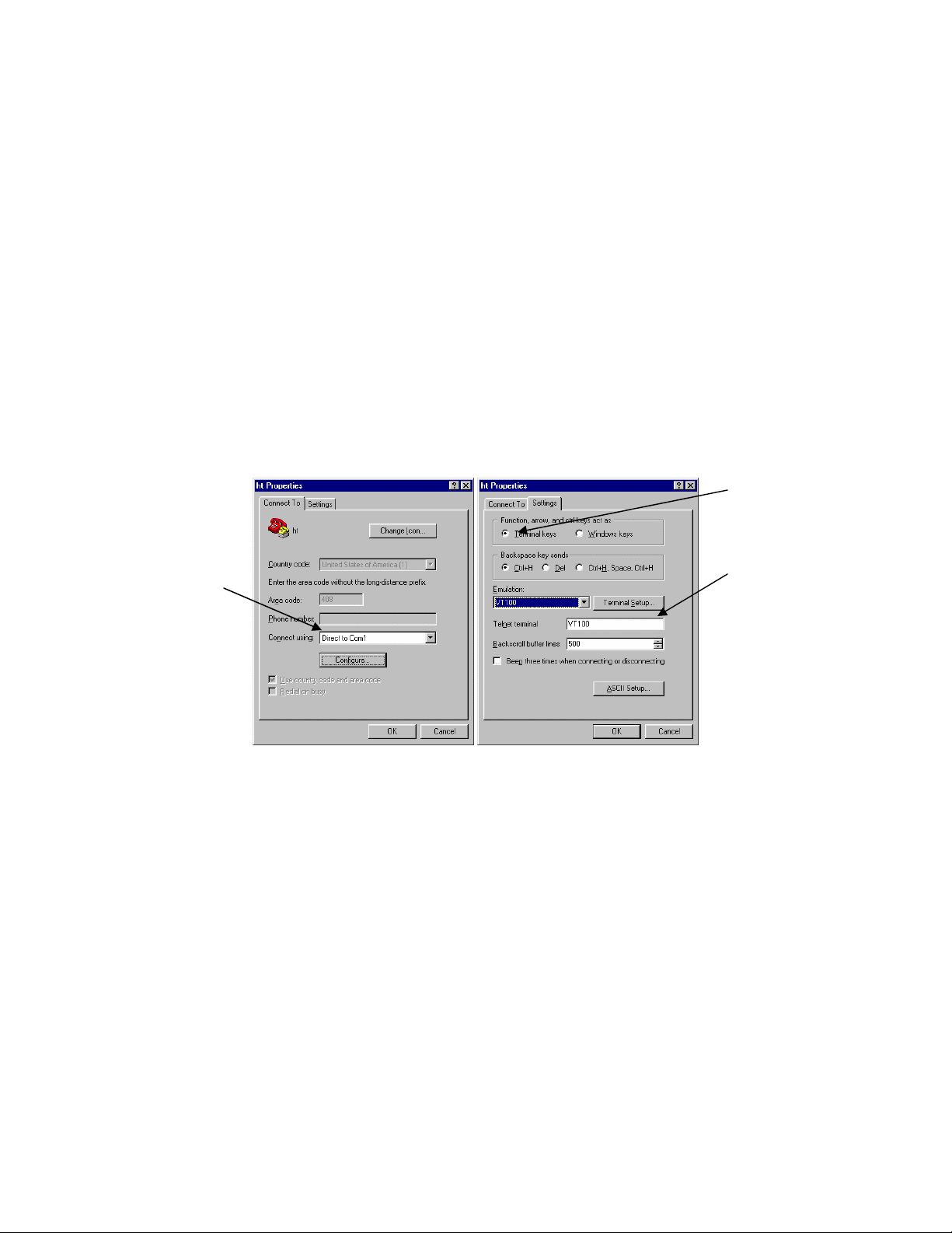
9. Set up a HyperTerminal (or equivalent terminal program) in the following manner:
a. Open the HyperTerminal program, and from its file menu, right-click on Properties.
b. Under the Connect To tab, choose the appropriate COM port (such as COM1 or COM2).
c
d
b
c. Under the Settings tab, choose Select Terminal keys for Function, Arrow, and Ctrl keys. Be sure the setting
is for Terminal keys, NOT Windows keys
d. Choose VT100 for Emulation mode.
20 Asante IC3724PWR User’s Manual
Page 21
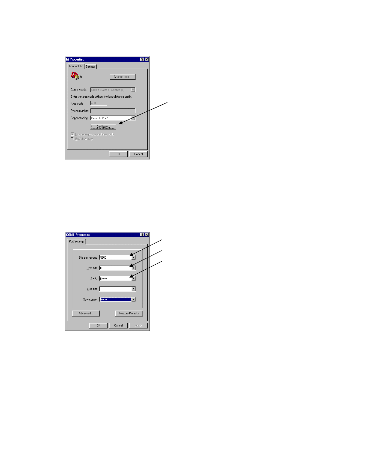
e. Press the Configuration button from the Connect To window.
e
f. Set the data rate to 9600 Baud.
g. Set data format to 8 data bits, 1 stop bit and no parity.
h. Set flow control to NONE.
f
g
h
Now that terminal is set up correctly, power on the switch. The boot sequence will display in the terminal.
After connecting to the console, you will be asked for a password
The initial default password for access using either the console or telnet is Asante (case-sensitive). Refer to the
following section for setting passwords on the terminal lines.
21 Asante IC3724PWR User’s Manual
Page 22

3.2 Connecting to a PC
You can connect to the switch through a PC by using either an Ethernet or USB cable. Using a telnet session, you
can telnet into the switch. The default IP address is 192.168.0.1. The case-sensitive default password is Asante.
3.3 Username and Password
The default Username/Password is admin/Asante.
3.4 Configuring an IP Address
The switch ships with the default IP address 192.168.0.1/255.255.255.0. Connect through the serial port in order to
assign the switch an IP address on your network.
The physical ports (or switchports) of the IntraCore 3724PWR are L2 ports, and cannot have an IP address assigned
to them. By default, each switchport belongs to VLAN 1. Use the following instructions to configure an IP address to
the switch. Follow the steps below to change the switch’s IP address.
1. Connect to the console and Enter at the Username prompt the username and pass word as described above.
2. The screen displays the user mode prompt, COMMAND>.
3. Type enable. Enter username and password. The new prompt is Switch#.
4. Type configuration. The new prompt is Switch(config)#.
5. Type network parms <ip address> <subnet mask> <default gateway>
Switch# configuration
Switch(config)# network parms 192.168.0.10 255.255.255.0 192.168.0.254
Switch(config)# exit
Switch# save
Switch# show network
MAC Address: 00-03-6d-ff-ef-4c
Management VLAN: 1
STATIC
IP: 192.168.0.10
Netmask: 255.255.255.0
Gateway: 192.168.0.254
22 Asante IC3724PWR User’s Manual
Page 23

3.5 Restoring Factory Defaults
To restore the switch to its factory default settings, follow the commands shown in the following screen.
COMMAND> enable
Switch# clear config
Switch# save
Important: To retain configuration changes after a system reload you must save changes made in running
configuration. From the privileged level, configurations can be saved using the save command.
The switch is ready for configuration. Refer to the following chapters for management and configuration information.
23 Asante IC3724PWR User’s Manual
Page 24

Chapter 4: Understanding the Command Line Interface (CLI)
The switch utilizes Command Line Interface (CLI) to provide access to several different command modes. Each
command mode provides a group of related commands. In general, after typing a command name, always press
‘enter’ to start the execution of the command.
After logging into the system, you are automatically in the user top (user EXEC) mode. Fr om the user top mode you
can enter into the privileged top (privileged EXEC) mode. From the privileged EXEC level, you can access the global
configuration mode and specific configuration modes: interface and Switch configuration. Entering a question mark
(?) at the system prompt provides a list of commands available for each command mode.
Document Conventions
Command descriptions use the following conventions:
• Vertical bars ( | ) separate alternative, mutually exclusive, elements
• Braces ({ }) indicate a required choice
• Boldface indicates commands and keywords that are entered literally as shown
• Italics indicate arguments for which you supply values
Access Each Command Mode
The following sections describe how to access each of the CLI command modes:
• User Top Mode: COMMAND>
• Privileged Top Mode: Switch#
• Global Configuration Mode: Switch(config)#
• Interface Configuration Mode: Switch(interface #)#
4.1 User Top (User EXEC) Mode
After you log in to the Switch, you are automatically in user top (user EXEC) command mode. The user-level prompt
consists of the ‘COMMAND’ followed by the angle bracket (>):
24 Asante IC3724PWR User’s Manual
Page 25

COMMAND>
The user top commands available at the user level are a subset of those available at the privileg ed level. In general,
the user top commands allow you ping remote hosts and show port statistics.
To list the commands available in user top mode, enter a question mark (?). Use a space and a question mark (?)
after entering a command to see all the options for that particular command.
Command Purpose
?
show ?
User top commands:
COMMAND> ?
Help Displays Help information
? Displays Help information
logout Exit
ping Pings a remote host
show Display commands
enable Enter XCLI interface
You may also enter a question mark after a letter or string of letters to view all the commands that start with that letter
(with no space between the letter and the question mark). Please note that there is no help on the argum ents after a
command is typed.
Lists the user EXEC commands.
Lists all the options available for the given command.
Use ‘logout’ to logout from the switch.
4.2 Privileged Top (Privileged EXEC) Mode
Because many of the privileged commands set the system configuration parameters, privileged access can be
password protected to prevent unauthorized use. The privileged command set includes those commands contained
in user EXEC mode, as well as the configure command through which you can access the remaining command
modes. The following example shows how to access privileged EXEC mode. Notice the prompt changes from
COMMAND> to Switch#:
To execute a command, the command and its arguments or key words must be entered in their entirety. However, a
partially typed command, argument or key word can be completed by pressing the ‘tab’ key.
25 Asante IC3724PWR User’s Manual
Page 26

COMMAND> enable
Username : admin
Password : xxxxxx
Switch#
Command Purpose
COMMAND> enable
Switch# ?
To return to user EXEC mode, use the exit command.
To list the commands available in top mode, enter a question mark (?) at the prompt, as shown in the following
example. Enter a question mark (?) after a command to see all the options for that command.
Switch> enable
Switch# ?
cable-diag Proceed cable diagnostic
clear Command to clear switch configuration or statistics
configuration Enter into global configuration mode
copy Upload file from switch to host, or download file to
Enters the privileged EXEC mode.
Lists privileged EXEC commands.
switch from host
exit Exit current shell
help Displays Help information
logout Exit current shell
ping Proceed ping destination host
reload Reboot System
save Save configuration
show Show configured data
telnet Telnet the other host
Important: To retain configuration changes after a system reload you must save changes made in running
configuration. From the privileged level, configurations can be saved using the save command.
26 Asante IC3724PWR User’s Manual
Page 27

4.3 Global Configuration Mode
Global configuration commands apply to features that affect the system as a whole, rather than just one protocol or
interface. Commands to enable a particular routing function are also global configuration commands. To enter the
global configuration mode, use the configure command.
The following example shows how to access and exit global configuration mode and list global configur ation
commands.
Command Purpose
Switch# configuration
Switch(config)# ?
To exit global configuration command mode and return to privileged EXEC mode, use one of the following
commands:
Command Purpose
exit
To list the commands available in global configuration mode, enter a question mark (?) at the prompt, as shown in the
following example. Enter a question mark (?) after a specific command to see all the options for that command.
Switch(Config)# ?
From privileged EXEC mode, enters global configuration mode.
Lists the global configuration commands.
Exits global configuration mode and returns to privileged EXEC mode.
exit Exit current shell
link-aggregation Configure link aggregation
vlan Configure VLAN
arp Configure ARP functions
access-list Configure Access-list
bridge Configure switch aging time
dos Configure denial of service
lacp-syspri Configure LACP system priority
lldp Configure LLDP
27 Asante IC3724PWR User’s Manual
Page 28

log Configure log server
radius-server Configure radius server
static-address Static address
mgmt-accesslist Set management access list, allows up to 8 IP addresses
monitor Configure port mirroring
dot1x Configure 802.1x parameters
network Configuration for inband connectivity
port-all Configure all switch ports
qos Configure QoS
rmon Configure Remote Monitoring
set Configure IGMP and static multicast
snmp Configure SNMP parameters
sntp Configure SNTP
https Configure SSL
spanning-tree Configure spanning-tree
tacplus Configure tacacs+
user Change user password
interface Enter into configure interface mode
green-eth Configure Green Ethernet enable or disable
Switch(Config)#
From global configuration mode, you can access three additional configurat ion modes: Use the interface command
to access its configuration modes.
4.3.1 Interface Configuration Mode
Many features are enabled on a per-interface basis. Interface configuration commands modify the operation of an
interface such as an Ethernet or serial port. Interface configuration commands always follow an interface global
configuration command, which defines the interface type as Ethernet.
In the following example shows configuration of Ethernet interface 1. The new prompt, Switch(interface 1)#,
indicates the interface configuration mode. In this example, the user asks for help by requesting a list of commands.
28 Asante IC3724PWR User’s Manual
Page 29

Switch(Config)# interface 1
Switch(Interface 1)# ?
exit Exit current shell
dot1x Configure 802.1x mode
lacp Configure port LACP mode
addport Add one port to a LAG group
delport Remove a port from a LAG group
lldp Configure lldp port level settings
admin-mode Configure administrative mode on a port
auto-negotiate Configure auto-negotiate mode on a port
speed Configure port phy parameter
flow-control Configure port flow control
port-security Configure port security
qos Configure port-based QoS priority mapping
rate-limit Configure rate limit on a port
storm-control Configure storm control on a port
rmon-counter Configure RMON counter capability on a port
set Configure an IGMP router port
spanning-tree Configure port spanning-tree
vlan Configure VLAN properties on a port
interface Change to another interface
Switch(Interface 1)#
To exit interface configuration mode and return to global configuration mode, enter the exit command. To exit
configuration mode and return to top mode, use the exit command.
4.4 Advanced Features Supported within the Command Mode
Enter a question mark (?) at the system prompt to display a list of commands available for each command mode. You
can also get a list of any command's associated keywords and arguments with the context-sensitive help feature.
29 Asante IC3724PWR User’s Manual
Page 30

To get help specific to a command mode, a command, a keyword, or an argument, perform one of the following
commands:
Command Purpose
Help
?
Obtain a brief description of the help system in any command mode.
List all commands available for a particular command mode.
When using context-sensitive help, the space (or lack of a space) before the question mark (?) is significant. To
obtain a list of commands that begin with a particular character sequence, type in those characters followed
immediately by the question mark (?). Do not include a space. This form of help is word help, because it completes a
word for you.
To list keywords or arguments, enter a question mark (?) in place of a keyword or argument. Include a space before
the question mark (?). This form of help is command syntax help, because it reminds you which keywords or
arguments are applicable based on the command, keywords, and arguments you already have entered.
Example of Context Sensitive Help
The following example illustrates how the context-sensitive help feature creates an acc ess list from the configuration
mode.
Enter the letters “co” at the system prompt followed by a question mark (?). Do not leave a space between the last
letter and the question mark (?). The system provides the commands that begin with co.
Switch# co?
configuration Enter configuration mode
copy Copy from one file to another
Switch# co
Enter the configure command followed by a space and a question mark (?) to list the command’s keyword(s) and a
brief explanation:
Switch# configuration ?
<cr>
Note that in the example below, if you enter the ip command followed by the Return Key or Enter, the system returns
the prompt that the command is incomplete.
Switch# copy
% Invalid command input
Switch#
30 Asante IC3724PWR User’s Manual
Page 31

Generally, uppercase letters represent variables. For example, after entering a command, such as hostname, and
using a space and a question mark, you will be prompted for the new name, represented b y WORD. In cases where
an IP address is the variable, the uppercase letters A.B.C.D will represent it.
Switch(config)# network parms ?
A.B.C.D Enter IP address of the switch
In the following access list example, seven further options are listed after the question mark. Note that what is typed
so far is preserved after the display.
Switch(Config)# access-list name acl_1 ?
add Create a new access-list
action Specify the action of the ACL entry
clear Clear ACL entry contents
delete Remove the ACL entry
enable Enable the ACL entry
disable Disable the ACL entry
set Set ACL entry contents
Switch(Config)# access-list name acl_1
4.5 Using CLI Command History
The CLI user interface provides a history or record of commands that you have entered . This feature is particularly
useful for recalling long or complex commands or entries, including access lists. To recall commands from the history
buffer, use one of the following commands:
Keystrokes/Command Purpose
Press the up arrow key Recall commands in the history buffer, beginning with the most
recent command. Repeat the key sequence to recall successively
older commands.
Press the down arrow key Return to more recent commands in the history buffer after recalling
commands with Ctrl-P or the up arrow key. Repeat the key
31 Asante IC3724PWR User’s Manual
Page 32

sequence to recall successively more recent commands.
4.6 Using Command-Line Editing Features and Shortcuts
A variety of shortcuts and editing features are enabled for the CLI command-line interface. The following subsections
describe these features:
• Moving Around on the Command Line
• Completing a Partial Command Name
• Editing Command Lines that Wrap
• Deleting Entries
• Scrolling Down a Line or a Screen
• Redisplaying the Current Command Line
• Transposing Mistyped Characters
• Controlling Capitalization
4.6.1 Moving Around on the Command Line
Use the following keystrokes to move the cursor around on the command line in order to make corrections or
changes:
Keystrokes Purpose
Press the left arrow. Move the cursor back one character.
Press the right arrow. Move the cursor forward one character.
Note: The arrow keys function only on ANSI-compatible terminals such as VT100s.
32 Asante IC3724PWR User’s Manual
Page 33

4.6.2 Completing a Partial Command Name
If you cannot remember a complete command name, press the Tab key to allow the system to complete a partial
entry.
Keystrokes Purpose
Enter the first few letters and press Tab.
In the following example, when you enter the letters “conf” and press the Tab key, the system provides the complete
command:
Router# conf<Tab>
Router# configuration
The command is not immediately executed, so that you may modify the command if necessary.
You may also enter a question mark (?) to obtain a list of commands that begin with that set of characters. Do not
leave a space between the last letter entered and the question mark (?). For example, two commands in privileged
mode start with co. To see what they are, type co? at the privileged EXEC prompt:
Switch# co?
configuration copy
Switch# co
Complete a command name.
4.6.3 Deleting Entries
Use any of the following commands to delete command entries if you make a mistake or change yo ur mind:
Keystrokes Purpose
Press Backspace.
Erase the character to the left of the cursor.
33 Asante IC3724PWR User’s Manual
Page 34

Chapter 5: Managing the System and Configuration Files
This chapter explains how to manage the system information, as well as how to manage the configuration files for
IntraCore 3724PWR.
5.1 Managing the System
This section discusses the following tasks needed to manage the system information of the IntraCore 3724PWR:
• Setting the System Clock
• Configuring the Host name
• Changing the Password
• Testing Connections with Ping Commands
• Tracing Packet Routes
• Enabling Syslog
• Displaying the Operating Configuration
5.1.1 Setting the System Clock
The IntraCore 3724PWRhas a battery-backed system clock that is accurate even after a system restart.
To manually set the system clock, complete the following commands in privileged
configuration mode. Use a space and a question mark (?) to display the clock set
options. Save after configuring the clock by typing save at the switch# prompt.
Switch(Config)# sntp
daylight Enable or disable the daylight saving configuration
localtime Configure the local time
server
timezone
Switch(Config)# sntp localtime
enable Enable local time
localtime_date Set local time
Switch(Config)# sntp localtime localtime_date
<2007..2037> Enter year
Switch(Config)# sntp localtime localtime_date 2008 07 06 06 35 00
Switch(Config)#
34 Asante IC3724PWR User’s Manual
Page 35

5.1.2 Specify the Hostname
The factory-assigned default host name is Switch. To specify or modify the host name for the network, use the
Network sysinfo sysname global configuration command.
Command Purpose
Network sysinfo sysname name
This systems hostname.
5.1.5 Test Connections with Ping Tests
The switch supports IP ping, which can be used to test connectivity to remote hosts, via their IP addresses. Ping
sends an echo request packet to an address and “listens” for a reply. The ping request will receive one of the
following responses:
• Normal response—The normal response occurs in 1 to 10 seconds, depending on network traffic
• Request timed out—There is no response, indicating a connection failure to the host, or the host has discarde d
the ping request
Beginning in user mode, use this command to ping another device on the network from the switch:
Command Purpose
ping address
Send an ICMP echo message to a designated host for testing
connectivity.
5.1.3 Enable the System Log
The IntraCore 3724PWR sends syslog messages to manager servers. Syslog messages are collected by a standard
UNIX or NT type syslog daemon.
Syslog enables the administrator to centrally log and analyze configuration events and system error messages such
as interface status, security alerts, environmental conditions, and CPU process overloads.
To log messages, use the following command in global configuration mode.
Command Purpose
log address
log facility
log trap
IP address of the host to be used as a syslog server.
Facility parameters for syslog messages.
Set syslog server logging level.
5.1.4 Displaying the Operating Configuration
The configuration file may be displayed from the EXEC (enable) mode.
To see the current operating configuration, enter the following command at the enable prompt:
35 Asante IC3724PWR User’s Manual
Page 36

Switch# show running-config
5.2 Managing Configuration Files
This section discusses how to download configuration files from remote servers, and store configuration files on the
switch at system startup.
Configuration files contain the commands the switch uses to customize the function of the IC3724PWR. The setup
command facility helps you create a basic configuration file. However, you can manually change the configuration by
typing commands in a configuration mode.
5.2.1 Configuring from the Terminal
The configuration files are stored in the following places:
• The running configuration is stored in RAM
• The startup configuration is stored in nonvolatile random-access memory (NVRAM)
To enter the configuration mode, enter the configuration command at the privileged EXEC prompt. The software
accepts one configuration command per line. You can enter as many configuration co mmands as you want.
You can add comments to a configuration file describing the commands you have entered. Precede a comment with
an exclamation point (!).
5.2.2 Copying Configuration Files to a Network Server
You can copy configuration files from the switch to a file server using TFTP. You might wish to back up a current
configuration file to a server before changing its contents, thereby allowing you to later restore the original
configuration file from the server.
Important: TFTP is not a secure protocol. Your server IP address and configuration file name will not be protected
over the public Internet. Use TFTP only on a trusted LAN connection.
To specify that the running or startup configuration file be stored on a TFTP network server, use the following
commands in the EXEC mode.
The following is an example of copying the current configuration to a file called ‘July’ on s erver 192.168.123.100.
Switch# copy
nvram_config Backup switch configuration
system_image Backup switch runtime image
tftp Download configuration or runtime image from host to switch
Switch# copy nvram_config
tftp Specify tftp server
Switch# copy nvram_config tftp
A.B.C.D Enter tftp server IP address
36 Asante IC3724PWR User’s Manual
Page 37

Switch# copy nvram_config tftp 192.168.123.100
file Specify a filename
Switch# copy nvram_config tftp 192.168.123.100 file
WORD Enter filename for backup configuration
Switch# copy nvram_config tftp 192.168.123.100 file July
<cr>
Switch# copy nvram_config tftp 192.168.123.100 file July
Switch#
5.2.3 Copying Configuration Files from a Network Server to the Switch
You can copy configuration files from a TFTP server to the running configuration of the switch. You may want to do
this for one of the following reasons:
To restore a previously backed up configuration file.
10. To use the same configuration file for another switch. For example, you may add another switch to your
network and want it to have a similar configuration to the original switch. By copying the file to the new
switch, you can change the relevant parts rather than re-creating the whole file.
11. To load the same configuration commands onto all the switches in your network so that they all have the
same configurations.
The copy nvram_config command loads the configuration files into the switch as if you were typing the commands
in at the command line. The switch does not erase the existing running configuration befor e adding the commands
unless a command in the copied configuration file replaces a command in the existing co nfiguration file. For example,
if the copied configuration file contains a different IP address in a particular command than the existing configur ation,
the IP address in the copied configuration is used. However, some commands in the existing configuratio n may not
be replaced or negated. In this case, the resulting configuration file will be a mixture of the existing confi guration file
and the copied configuration file, with the copied configuration file having precedence.
To copy a configuration file from a TFTP server to the switch, use one of the following commands in EXEC mode:
Command Purpose
Switch# copy tftp 192.168.123.254 file cfg_file nvram_config
Copy the config file ‘cfg_file’ from a TFTP
server 192.168.123.254 to the switch.
To clear the saved configuration and restore configuration to default value s, use the following command from
privileged mode:
37 Asante IC3724PWR User’s Manual
Page 38

Switch# clear config
Don’t forget to use ‘save’ command to preserve the new configuration across reboots.
5.3 Managing system image Files
This system image file is stored in the non-volatile flash in the switch. It is the software that runs in the switch after
power up. It provides user interfaces (CLI, Web, telnet) for user to control and manage the switch. The following
describes the commands that save the system image to a file in a host TFTP server and download a new version
system image from a TFTP server to the switch.
5.3.1 Saving System image to a Network Server
You can save the system image file of the switch to a file server using TFTP. You might wish to back up the current
system image file to a server , thereby allowing you to later restore the original system image from the server in case
of system image file corruption.
To save the system image file of the switch to a TFTP server, use one of the following commands in EXEC mode:
Command Purpose
copy system_image tftp 192.168.0.254 file ttt sysimg_file
Copy the system image the file ‘sysimg_file’ to
TFTP server 192.168.0.254.
5.3.2 Replacing System image from a Network Server
You can replace the system image file of the switch from a file in a server using TFTP. You can update the current
system image with a newer version in this fashion.
To replace the system image file of the switch from a TFTP server, use one of the following commands in EXEC
mode:
Command Purpose
copy tftp 192.168.0.254 file new_sysimg system_image
Copy the system image the file ‘new_sysimg’ from
TFTP server 192.168.0.254 to the switch.
5.4 Configuring SNMP
This section discusses the following tasks needed to configure Simple Network Management Protocol (SNMP).
38 Asante IC3724PWR User’s Manual
Page 39

5.4.1 Configuring SNMP Support
The Simple Network Management Protocol (SNMP) system consists of three parts: an SNMP manager, an SNMP
agent, and a Management Information Base (MIB). SNMP is an application-layer protocol that allows SNMP manager
and agent stations to communicate. SNMP provides a message format for sending information between an SNMP
manager and an SNMP agent. The agent and MIB reside on the switch. In configuring SNMP on the switch, the
relationship between the manager and the agent must be defined.
The SNMP agent gathers data from the MIB, which holds the information about device parameters and network data.
The agent also responds to the manager’s requests to get or set data. An agent can also send unsolicited traps to the
manager. Traps are messages alerting the SNMP manager to a specific event on the network. Such events include
improper user authentication, restarts, link status (up or down), closing of a TCP connection, or loss of connection to
a neighboring switch. An SNMP manager can request a value from an agent, or store or change a value in that agent.
To configure support for SNMP on the switch, perform the following tasks:
• Create an SNMP user group
Command Purpose
Switch(Config)# snmp group add read_grp version 1 access ro
• Create an SNMP user of the group just created
Command Purpose
Switch(Config)# snmp user add user_read group read_grp version 1
• Create a community string and management station
Command Purpose
Create a ‘read_only’ version 1group
‘read_grp’
Create a version 1 user ‘user_read’ of
group ‘read_grp’
snmp community add public group read_grp mgmt-ip 192.168.123.100
39 Asante IC3724PWR User’s Manual
Create a community string
‘public’ for group ‘read_grp’ that
can be used by management
host 192.168.123.100
Page 40

• Define SNMP Trap Operations
Command Purpose
snmp trapstation add 192.168.123.100 community public type linkchange
trap-version 1
Create a trap host
192.168.123.100 to which the
switch can send version 1 link
change trap messages using
community string ‘public’.
5.5 Spanning Tree Algorithm
The Spanning Tree Protocol (STP) is part of the IEEE 802.1D standard. It provides for a redundant network without
the redundant traffic through closed paths. For example, in a network without spanning tree protocol, the same
message will be broadcast through multiple paths, which may start an unending packet-passing cycle. This in turn
causes a great amount of extra network traffic, leading to network downtime. The STP reduces a network like this,
with multiple, redundant connections, to one in which all points are connected, but where there is only one path
between any two points (the connections span the entire network, and the paths are branched, like a tree).
All of the bridges (a switch is a complex bridge) on the network communicate with each other using special packets of
data called Bridge Protocol Data Units (BPDUs). The information exchanged in the BPDUs allo ws the b r idges on the
network to do the following:
• Elect a single bridge to be the root bridge
• Calculate the shortest path from each bridge to the root bridge
• Select a designated bridge on each segment, which lies closest to the root and forwards all traffic to it
• Select a port on each bridge to forward traffic to the root
• Select the ports on each bridge that forward traffic, and place the redundant ports in blocking states
5.5.1 Spanning Tree Parameters
The operation of the spanning tree algorithm is governed by several parameters.
Forward Time
After a recalculation of the spanning tree, the Forward Time parameter regulates the delay before each port begi ns
transmitting traffic. If a port begins forwarding traffic too soon (before a new root bridge has been selected), the
network can be adversely affected. The default value for Forward Time is 15 seconds.
Hello Time
This is the time between BPDUs transmitted by each bridge. The default setting is 2 seconds.
Maximum Age
40 Asante IC3724PWR User’s Manual
Page 41

Each bridge should receive regular configuration BPDUs from the direction of the root bridge. If the maximum age
timer expires before the bridge receives another BPDU, it assumes that a change in the topology has occurred, and it
begins recalculating the spanning tree. The default setting for Maximum Age is 20 seconds.
Note: The above parameters (Hello Time, Maximum Age, and Forward Time) are constrained by the follo wing
formula:
(Hello Time + 1) <= Maximum Age <= 2 x (Forward Delay – 1)
Priority
Setting the bridge priority to a low value will increase the likelihood that the current bridge will become the root bridge.
If the current bridge is located physically near the center of the network, decrease the Bridge Priority from its default
value of 32768 to make it become the root bridge. If the current bridge is near the edge of the network, it is best to
leave the value of the Bridge Priority at its default setting.
In general, reducing the values of these timers will make the spanning tree react faster when the topology changes,
but may cause temporary loops as the tree stabilizes in its new configuration. Increasing the values of these timers
will make the tree react more slowly to changes in topology, but will make an unintended reconfiguration less likely.
All of the bridges on the network will use the values set by the root bridge. It is only necessary to reconfigure that
bridge if changing the parameters.
Port Priority
The port priority is a spanning tree parameter that ranks each port, so that if two or more ports have the same path
cost, the STP selects the path with the highest priority (the lowest numerical value). By changing the priority of a port,
it can be more, or less, likely to become the root port. The default value is 128, and the value range is 0–255.
Port Path Cost
Port path cost is the spanning tree parameter that assigns a cost factor to each port. The lower the assigned port
path cost is, the more likely that port will be accessed. The default port path cost for a 10 Mbps or 100 Mbps port is
the result of the equation:
Path cost = 1000/LAN speed (in Mbps)
Therefore, for 10 Mbps ports, the default port path cost is 100. For 100 Mbps ports, it is 10. To allow for faster
networks, the port path cost for a 1000 Mbps port is set by the standard at 4.
5.5.2 Rapid Spanning Tree Protocol (RSTP)
Rapid Spanning Tree Protocol makes use of point-to-point link type and expedites into a rapid convergence of the
spanning tree. Re-configuration of the spanning tree can occur in less than 1 second (as opposed to 50 seconds with
the default settings in the legacy spanning tree), which is critical for networks carrying delay-sensitive traffic, such as
voice and video.
Port Roles and the Active Topology
RSTP provides rapid convergence of the spanning tree by assigning port roles and by determining the active
topology. RSTP uses the same underlying spanning tree calculation and algor ithm as legacy STP to select the bridge
with the highest bridge priority (lowest numerical priority value) as the root bridge. Then RSTP assigns one of these
port roles to bridge ports:
• Root port—provides the best path (lowest cost) when the bridge forwards packets to the root switch.
41 Asante IC3724PWR User’s Manual
Page 42

• Designated port—connects to the designated switch, which has the lowest path cost when forwarding packets
from that LAN to the root bridge. The port through which the designated switch is attached to the LAN is called
the designated port.
• Alternate port—offers an alternate path toward the root switch to that provided by the current root port.
• Backup port—acts as a backup for the path provided by a designated port toward the leaves of the spanning
tree. A backup port can exist only when two ports are connected together in a loop-back by a point-to-point link
or when a switch has two or more connections to a shared LAN segment.
• Disabled port—has no role in the operation of the spanning tree.
A port with the root or a designated port role is included in the active topology. A port with the alternate or backup port
role is excluded from the active topology.
Rapid Convergence
RSTP provides for rapid recovery of connectivity following the failure of a switch, switch port, or LAN. It provides rapid
convergence for edge ports, new root ports, and ports connected through point-to-point links as follows:
• Edge ports—If a port on a switch running RSTP is assigned to be a edge port, it will be put to forwarding
immediately. However, the edge port will be in the RSTP initialization state and will send out the RSTP BPDUs
with the operating status of edge port set to TRUE. If the edge port starts receiving the BPDUs, it will change the
operating edge state to FALSE and start the spanning tree calculations. It is recommended to assign any ports
that are to be left as a “leaf” of the LAN (with no connection to any bridge) as edge ports.
• Root ports—If the RSTP selects a new root port, it blocks the old root port and immediately transitions the new
root port to the forwarding state.
• Point-to-point links—If you connect a port to another port through a point-to-point link and the local port becomes
a designated port, it negotiates a rapid transition with the other port by using the proposal-agreement handshake
to ensure a loop-free topology.
Note that if the link type of the port is not forced, the switch makes the decision of link type by operating duplex mode
of the port. Also, a port with full-duplex mode is considered as a point-to-point link type, and a port in half-duplex
mode is set as shared link type.
5.5.3 Configuring spanning-tree
Enabling/Disabling Spanning-tree
Use the configuration mode command below to enable/disable spanning tree on the switch.
Command Purpose
spanning-tree forceversion 8021w
spanning-tree forceversion none
Enable Rapid spanning-tree(802.1W) on the
switch.
Disable spanning tree on the switch
42 Asante IC3724PWR User’s Manual
Page 43

Configuring Switch/Bridge Priority
For <priority> the range is 0 to 61440 in increments of 4096; the default is 32768. The lower number is used when
you want to specify the switch as the root switch.
Valid priority values are 0, 4096, 8192, 12288, 16384, 20480, 24576, 28672, 32768, 36864, 40960, 45056, 49152,
53248, 57344, and 61440. All other values are rejected.
Command Purpose
spanning-tree priority 8192
Set switch priority to 8192
Configuring Link Type
Use the following interface mode command to configure port link-type:
Command Purpose
spanning-tree port force-p2plink enable ports 1-2
Set link type of port 1,2 to point to point
By default, the link type is determined from the duplex mode of the interface: a full-duplex port is considered to have a
point-to-point connection; a half-duplex port is considered to have a shared connection.
To return the switch to its default setting, use the following configuration command.
Command Purpose
spanning-tree port force-p2plink auto ports 1-2
Set link type of port 1,2 to auto
Configuring an Edge Port
Use the following interface mode command to configure port link type:
Command Purpose
spanning-tree port edge enable ports 1-2
Set port 1,2 to edge port
43 Asante IC3724PWR User’s Manual
Page 44

The default setting is no edge port configuration.
To return the switch to its default setting, use the following configuration command.
Command Purpose
spanning-tree port edge disable ports 1-2
Set port 1,2 to non edge port
Configuring Port Path Cost
Use the following interface mode command to configure port path cost:
Command Purpose
spanning-tree port cost 1000 ports 1-2
Set path cost of port 1,2 to 1000
The default values for path cost are determined by the operating port speed:
• For ports operating in 1000Mb speed, the path cost is 20000
• For ports operating in 100Mb speed, the path cost is 200000
• For ports operating in 10Mb speed, the path cost is 2000000
To return the switch to its default setting, use the following configuration command.
Command Purpose
spanning-tree port cost 0 ports 1-2
Set path cost of ports 1,2 to default values
Configuring Port Priority
Use the following interface mode command to configure port priority:
Command Purpose
spanning-tree port priority 10 ports 1-2
Set priority of ports 1,2 to 10
44 Asante IC3724PWR User’s Manual
Page 45

For <port-priority>, the range is 0–240 in increments of 16; the default is 128. The lower the number, the higher the
priority.
45 Asante IC3724PWR User’s Manual
Page 46

Chapter 6: Configuring IP
The Internet Protocol (IP) is a packet-based protocol used to exchange data over computer networks. All other IP
protocols are built on the foundation. IP is a network-layer protocol that contains addressing and control information
that allows data packets to be routed.
The table below lists the traditional classes and ranges of IP addresses and their status.
Class Address or Range Status
A 0.0.0.0
1.0.0.0 to 126.0.0.0
127.0.0.0
B 128.0.0.0 to 191.0.0.0
255.255.255.0
C 192.0.0.0 to
223.255.255.0
D 224.0.0.0 to 239.255.255.255 Multicast group addresses
E 240.0.0.0 to 255.255.255.254
255.255.255.255
With the rapid expansion of networks being connected to the Internet, critical problems were seen with the traditional
classified addressing scheme. It was possible that IP addresses would run out, and routing tables would be
overwhelmed. Thus, the Classless Inter-Domain Routing (CIDR) addressing scheme was created.
CIDR replaces the older process of assigning IP addresses with general prefixes of 8, 16, or 24 bits. CIDR uses
prefixes of 13 to 27 bits. A CIDR address includes the standard 32-bit IP address and adds information on how many
bits are used for the network prefix. In the IP address 206.203.1.35/27, the “/27” indicates that the first 27 bits are
used to identify the unique network, and the remaining bits are used to identify the specific host. Now, blocks of
addresses can be better fitted to even very small or very large networks.
Reserved
Available
Reserved
Available
Available
Reserved
Broadcast
The following table describes the Class C equivalent of CIDR prefixes.
CIDR Prefix Class C Equivalent Host Addresses
/27 1/8 Class C 32 Hosts
/26 1/4 Class C 64 Hosts
/25 1/2 Class C 128 Hosts
/24 1 Class C 256 Hosts
/23 2 Class C 512 Hosts
/22 4 Class C 1,024 Hosts
/21 8 Class C 2,048 Hosts
/20 16 Class C 4,096 Hosts
46 Asante IC3724PWR User’s Manual
Page 47

/19 32 Class C 8,192 Hosts
/18 64 Class C 16,384 Hosts
/17 128 Class C 32,768 Hosts
/16 256 Class C OR 1 Class B 65,536 Hosts
/13 2,048 Class C 524,288 Hosts
6.1 Establish Address Resolution
A device in the IP can have both a local address (which uniquely identifies the device on its local segment or LAN)
and a network address (which identifies the network to which the device belon gs). T he local address is more properly
known as a data link address because it is contained in the data link layer (Layer 2 of the OSI model) part of the
packet header and is read by data link devices (bridges and all device interfaces, for example). The more technically
inclined will refer to local addresses as MAC addresses, because the Media Access Control (MAC) sub-layer within
the data link layer processes addresses for the layer.
To communicate with a device on Ethernet, you first must determine the 48-bit MAC or local data link address of that
device. The process of determining the local data link address from an IP address is called ad dress resolution. The
IntraCore 3724PWR software uses the Address Resolution Protocol (ARP) for address resolution. ARP is used to
associate IP addresses with media or MAC addresses. Taking an IP address as input, ARP determines the
associated media address.
Once a media or MAC address is determined, the IP address/media address association is stored in an ARP cache
for rapid retrieval. Then the IP datagram is encapsulated in a link-layer frame and sent over the network.
47 Asante IC3724PWR User’s Manual
Page 48

6.2 Managing IP Multicast Traffic
Multicast traffic is a means to transmit a multimedia stream from the Internet (a video conference, for example)
without requiring a TCP connection from every remote host that wants to receive the stream.
Traditional IP communication allows a host to send packets to one host (unicast transmission) or to all hosts
(broadcast transmission). IP multicast provides a third scheme, allowing a host to send packets to a group of hosts
(group transmission). A multicast address is chosen for the members of a multicast group. Senders use that address
as the destination address of a datagram to reach all hosts of the group. The stream is sent to the multicast address,
and from there, it is delivered to all interested parties on the Internet. Any host, regardless of whether it is a member
of a group, can send to that group. However, only the members of the group receive the message.
The IntraCore IC3724PWR supports the snooping of Internet Group Management Protocol (IGMP) messages that
are used between hosts on a LAN and the switch(s)/routers on that LAN to track the multicast groups of which hosts
are members. The switch supports IGMP Version 2 that has such features as the IGMP query timeout and the
maximum query response time.
6.2.1 IGMP Overview
The Internet Group Management Protocol (IGMP) manages the multicast groups on a LAN. IP hosts use IGMP to
report their group membership to directly connected multicast switches. Switches executing a multicast protocol
maintain forwarding tables to forward multicast datagram’s. Switches use the IGMP to learn whether members of a
group are present on their directly attached sub-nets. Hosts join multicast groups by sending IGMP report messages.
IGMP uses group addresses, which are Class D IP addresses. The high-order four bits of a Class D address are
1110. Therefore, host group addresses can be in the range 224.0.0.0 to 239.255.255.255.
The address 224.0.0.0 will not be assigned to any group. The address 2 24.0.0.1 is assigned to all systems on a subnet. The address 224.0.0.2 is assigned to all switches on a sub-net.
Forwarding Unknown Multicast Packets. Unknown multicast packets are those packets with destination IP multicast addresses not learned by the switch. By default, the switch forwards all such traffic.
6.2.2 Configuring IGMP
Use the following commands to configure IGMP.
Enable the IGMP Snooping
To enable/disable IGMP, use the command below. Unknown multicast traffic will not be forwarded once igmp is
enabled.
Command Purpose
Set igmp {enable | disable}
Enable/Disable IGMP
48 Asante IC3724PWR User’s Manual
Page 49

Enable the IGMP querier
Multicast switches can send IGMP host-query messages to discover which multicast groups are present on attached
networks. These messages are sent to the all-systems group address of 224.0.0.1 with a time-to-live (TTL) value
of 1.
Multicast switches continue to periodically send host-query messages to refresh their knowledge of me mberships
present on their networks. If, after some number of queries, the switch software discovers that no local hosts are
members of a multicast group, the software stops forwarding onto the local network multicast packets from remote
origins for that group and sends a prune message upstream toward the source.
The switch can be configured to send IGMP queries which are used to solicit IGMP hosts report messages. The
switch uses the report messages to keep track of which ports belong to which IP multicast group.
To enable/disable IGMP querier , use the command below:
Command Purpose
set igmp-querier {enable | disable}
Enable/Disable IGMP querier
Modifying the IGMP Host-Query Message Interval
Multicast switches elect a designated switch for the LAN (subnet). The designated switch is the one with the highest
IP address. The switch is responsible for sending IGMP host-query messages to all hosts on the LAN. By default, the
designated switch sends IGMP host-query messages every 60 seconds i n order to kee p the IGMP overh ead o n hosts
and networks very low. To modify this interval, use the following command in interface configuration mode:
Command Purpose
set igmp query-interval <10-3600 seconds>
Configure the frequency at which the designated switch sends
IGMP host-query messages.
The following example shows setting the IGMP query interval to 200.
Switch(config)# set igmp query-interval 200
Changing the Maximum Query Response Time
By default, the maximum query response time advertised in IGMP queries is 10 seconds. If the switch is using IGMP
Version 2, you can change this value. To change the maximum query response time, use the following command in
configuration mode:
Command Purpose
set igmp query-resinterval <0-200 seconds>
Set the maximum query response time advertised
in IGMP queries.
49 Asante IC3724PWR User’s Manual
Page 50

6.3 Access Lists
An access list is a criteria statement that the switch uses to determine whether to allow or block traffic based on MAC
addresses, IP addresses, or UDP/TCP ports. Access lists can be configured to provide basic security on your
network, and to prevent unnecessary traffic between network segments. Access lists are applied to inbound traffic
only.
When configuring an access list, an argument of ‘priority’ must be specified. The priority of an ACL is important, as
the switch tests addresses of each packet against the criteria in access lists one by one (in the order of the priority)
until it finds a match. One of the arguments in specifying the access list is the ‘mask’ that comes after a MAC
address or IP address. This argument identifies which bits in the address field are to be matched. A “1” indicates that
positions must match; a “0” indicates that position is ignored
The check of a match comes first for an access list with lower priority(lower value) than those with higher priority
values. The last match determines whether the software accepts or rejects the address. In case of multiple matches,
the match in IP mode takes precedence over that in MAC mode. Because the switch goes through the whole set of
access lists to find matches, the priority of the ACL is critical.
Important! By default, if no conditions match, the switch allows the address.
The switch supports up to 256 access lists, and MAC address based access lists can not exceed 64.
An access list can be configured using the command and its arguments in configuration mode below:
access-list name acl1 ?
add Create a new access-list
action Specify the action of the ACL entry
clear Clear ACL entry contents
delete Remove the ACL entry
enable Enable the ACL entry
disable Disable the ACL entry
set Set ACL entry contents
6.3.1 Creating an Access List
To create an access list, use the command below:
Command Purpose
access-list name acl1 add priority 1
Create an access list named ‘acl_name’ with priority 1
6.3.2 Configuring an Access List
To configure an access list, use the command below:
50 Asante IC3724PWR User’s Manual
Page 51

Command Purpose
access-list name acl1 set ……
access-list name acl1 action ……
Set the criteria statement of an access list named ‘acl_name’
Specify the action to take if criteria of the access list is
matched
In the following example, an access list will be created to block traffic sent from MAC address 00-00-94-12-34-56.
Switch(Config)# access-list name acl_mac add priority 1
Switch(Config)# access-list name acl_mac set mac-mode macsa 00-00-94-12-34-56 ff-ffff-ff-ff-ff
Switch(Config)# access-list name acl_mac action deny
Switch(Config)#
In the next example, a standard access list will be created to deny all traffic from 192.168.123.254 , and allow all
other traffic to be forwarded.
Switch(Config)# access-list name acl_ip add priority 1
Switch(Config)# access-list name acl_ip set ip-mode srcip 192.168.123.254
255.255.255.255
Switch(Config)# access-list name acl_ip action deny
Switch(Config)#
In the following example, an access list will be created to deny Telnet traffic.
Switch(Config)# access-list name acl_tcp_src add priority 1
Switch(Config)# access-list name acl_tcp_src set ip-mode l4port src-port from 23 to 23
Switch(Config)# access-list name acl_tcp_dst add priority 2
Switch(Config)# access-list name acl_tcp set ip-mode l4port dst-port from 23 to 23
Switch(Config)# access-list name acl_tcp_src action deny
Switch(Config)# access-list name acl_tcp_dst action deny
Switch(Config)#
51 Asante IC3724PWR User’s Manual
Page 52

6.3.3 Applying an Access List to an Interface
After creating your access lists, you can choose interfaces for which the access lists will be applied. If no interfaces
are explicitly selected, the access list is applied to all interfaces.
To select the interface for an access list, use the following command:
Command Purpose
access-list name acl1 set portlist ……
In the next example, we will create an extended access list that will allow only SMTP bound traffic (port 25) to be
forwarded on port 7, and deny all other traffic.
Switch(Config)# access-list name acl_tcp_dst_smtp add priority 1
Switch(Config)# access-list name acl_tcp_dst_smtp set ip-mode l4port dst-port from 25
to 25
Switch(Config)# access-list name acl_tcp_dst_smtp set portlist 7
Switch(Config)# access-list name acl_tcp_dst_smtp action permit
Switch(Config)# access-list name acl_deny_all add priority 2
Switch(Config)# access-list name acl_deny_all set ip-mode l4port dst-port from 25 to
25
Switch(Config)# access-list name acl_deny_all set mac-mode macsa 00-00-94-12-34-56 0000-00-00-00
Select interfaces that the access list ‘acl1’ will be applied
Switch(Config)# access-list name acl_deny_all action deny
6.3.4 Enabling an Access List
To enable a configured access list, use the command below. All the examples above require execution of the ‘enable’
command to make the access lists effective.
Command Purpose
access-list name acl_name enable
52 Asante IC3724PWR User’s Manual
Enable an access list named ‘acl_name’ .
Page 53

Chapter 7: Power over Ethernet (PoE)
7.1 PoE Theory
Power-over-Ethernet (PoE) provides power to devices over existing LAN cabling, without updating or modifying the
network infrastructure. Power-over-Ethernet removes the need to place network devices next to a power source.
Examples include:
• IP Phones
• Wireless Access Points
• IP Gateways
• Cameras
• Audio remote monitoring equipment
As technology has progressed, PoE has evolved. Equipment from many manufacturers, including the Asante
IC3724PWR, supports the 802.3af standard. By default, the IC3724PWR is set to work with 802.3af compliant
devices. The 802.3af standard includes the ability to determine when a compliant Powered Device (PD) is
connected to a port. Power is only provided when a compliant device is detected. As per the standard, ports can be
set to provide different amounts of power. The IC3724PWR also includes features that allow the switch to be
configured differently to accommodate older, noncompliant equipment, using older detection methods, and to meet
special needs.
7.2 PoE Show Example To access the PoE feature, login to the switch and enter the username and
password. Next use the enable command to enter privileged mode. Once in enable mode, the sho w command can
be used to view the switch PoE settings. An example appears below.
Login: admin
Password: ******
COMMAND> en
Username: admin
Password: ******
Switch# show
53 Asante IC3724PWR User’s Manual
Page 54

Using help (?) the PoE subcommands and their functions can be identified.
Switch#
Switch# show poe
system-status Display PoE System Status
port-index Specify an switch poe interface
all Display all switch poe interface
Switch# show poe system-status
POE SW Version: 0.36
PoE Number: 12
Total Allocation(0.1W): 1000
Guard Band(0.1W): 80
Management Mode: Dynamic without priority
Total Consumption: 30700
Switch# show poe port-index
portindex(1,2,..) Switch poe interface index
Switch# show poe port-index 1
Port AdminStatus Priority P_allocation P_consumption P_detectiontype
__________________________________________________________________________
1 Enable NORMAL 15400 0 IEEE 802.3af 4-Point Detection only (Default)
Switch#
54 Asante IC3724PWR User’s Manual
Page 55

Switch# show poe all
Port AdminStatus Priority P_allocation P_consumption P_detectiontype
__________________________________________________________________________
1 Enable NORMAL 15400 8800 Legacy Capacitive Detection only
2 Enable NORMAL 15400 2900 IEEE 802.3af 4-Point Detection only (Default)
3 Enable NORMAL 15400 2900 IEEE 802.3af 4-Point Detection only (Default)
4 Enable NORMAL 15400 2000 IEEE 802.3af 4-Point Detection only (Default)
5 Enable NORMAL 15400 2900 IEEE 802.3af 4-Point Detection only (Default)
6 Enable NORMAL 15400 2900 IEEE 802.3af 4-Point Detection only (Default)
13 Enable NORMAL 15400 2900 IEEE 802.3af 4-Point Detection only (Default)
14 Enable NORMAL 15400 2900 IEEE 802.3af 4-Point Detection only (Default)
15 Enable NORMAL 15400 2900 IEEE 802.3af 4-Point Detection only (Default)
16 Enable NORMAL 15400 2900 IEEE 802.3af 4-Point Detection only (Default)
17 Enable NORMAL 15400 2900 IEEE 802.3af 4-Point Detection only (Default)
18 Enable NORMAL 15400 2700 IEEE 802.3af 4-Point Detection only (Default)
Switch#
7.3 PoE Interface Mode
To change settings on a port, enter the configuration interface mode.
55 Asante IC3724PWR User’s Manual
Page 56

Switch(Interface 1)# poe
func Configure poe function on a port
power-pri Configure power priority on a port
detection Configure detection type on a port
high-power Configure Power Energy Mode on a port
Func is the setting that enables or disables the poe function on a particular port.
Power-pri selects the priority policy to determine which ports still receive power is the maximum is
reached.
Static with priority: This mode considers the used power is port’s allocation and PSE provides the power to the port
with higher priority first.
Dynamic with priority: This mode considers the used power is port’s consumption and PSE provides the power to the
port with higher priority first.
Static without priority: This mode considers the used power is port’s allocation and PSE first provides the power to the
port which is first required.
Dynamic without priority: This mode considers the used power is port’s consumption and PSE first provides the
power to the port which is first required.
Detection Indicates which PoE detection type has been chosen.
No Detection: PSE will provide power to PD without detection.
Legacy Capacitive Detection only: PSE would provide three points to test PD’s capacitance. After a PD is
successfully detected, power is delivered to the port, or not.
IEEE 802.3af 4-Point Detection only (Default): PSE would provide four points voltage to test PD’s resistance.
After a PD is successfully detected, power is delivered to the port, or not.
IEEE 802.3af 4-Point followed by Legacy: PSE would provide four points voltage to test PD’s capacitance. After a
PD is successfully detected, power is delivered to the port, or not.
IEEE 802.3af 2-Point only: PSE would provide two points voltage to test PD’s resistance. After a PD is
successfully detected, power is delivered to the port, or not.
IEEE 802.3af 2-Point followed by Legacy: PSE would provide two points voltage to test PD’s capacitance. After a
PD is successfully detected, power is delivered to the port, or not.
The first 2 options(No Detection, Legacy..) can be used for older legacy POE devices if the default detection
method does not detect the PD.
High-power enables or disables the 30 watt power limit mode. The default is 15 watts.
7.4 PoE Interface Settings Example
Here is an example of possible settings
56 Asante IC3724PWR User’s Manual
Page 57

Switch(Interface 1)# poe func
enable Enable poe function on a port
disable Disable poe function mode on a port
Switch(Interface 1)# poe power-pri
level Power priority level
Switch(Interface 1)# poe power-pri level
low Set to low priority
normal Set to normal priority
middle Set to middle priority
high Set to high priority
Switch(Interface 1)# poe power-pri level normal
Switch(Interface 1)# poe detection
type detection type
Switch(Interface 1)# poe detection type
0 No Detection
1 Legacy Capacitive Detection only
2 IEEE 802.3af 4-Point Detection only (Default)
3 IEEE 802.3af 4-Point followed by Legacy
4 IEEE 802.3af 2-Point only
5 IEEE 802.3af 2-Point followed by Legacy
Switch(Interface 1)# poe detection type 2
Switch(Interface 1)# poe high-power
status detection type
Powered Devices (PDs) receive power over the Ethernet cable.
Switch(Interface 1)# poe high-power status
Guard Band protects the device from exceeding the Power Total Allocation. For example, if 100W is the Power
ToAllocation, and the Guard Band is 10W, if the total system power consumption exceeds 90W no additi onal PoE
on start High Power Mode
components can be added. The accumulated PoE components power consumption is rounded down for display
purposes. Due to hardware limitations, the power measurement accuracy is 4%.
off End High Power Mode
Switch(Interface 1)# poe high-power status off
57 Asante IC3724PWR User’s Manual
Page 58

Chapter 8: VLAN Configuration
VLANs are used to organize any group of network nodes into separate broadcast domains. VLANs confine broadcast
traffic to the originating group and eliminate broadcast storms in large networks. VLANs provide a secure and efficient
network environment.
VLANs are based on untagged port groups, or traffic can be explicitly tagged to identify the VLAN group to which it
belongs. Untagged VLANs can be used for small networks attached to a single switch. Tagged VLANs shou ld be
used for larger networks, and all the VLANs assigned to the inter-switch links.
Use the VLAN feature to partition a single IntraCore 3724PWR into a VLAN each containing its own set of ports.
Packets are forwarded only between ports belonging to the same VLAN. This allows you to restrict access from one
segment to another to increase network security or to reduce traffic. To set up VLANs you should specify the ports
belonging to the VLAN, and setup of tagging. The following shows the commands available to confi gure VLAN’s.
Switch(Config)# vlan ?
add Create a new VLAN
delete Remove a existed VLAN
port Configure 802.1Q port parameters for VLANs
lag Configure lag to a special VLAN
Switch(Config)# interface 4
Switch(Interface 4)# vlan ?
participation Join or leave a VLAN
protected Configure port protected property
dropnq Configure port drop no 8021q frame
ingress Configure port filter
pvid Configure port PVID
The switch is shipped with a default VLAN with VLAN ID (VID) 1. All switch ports are included in the default VID 1.
The default VID 1 cannot be deleted.
Up to 256 Virtual LANs (VLANs) are supported on the IntraCore 3724PWR. The default VLAN with VLAN ID (VID) 1.
All switch ports are included in the default VID 1. The default VID 1 cannot be deleted.
8.1 Creating or Modifying a VLAN
To create a VLAN with id 2, enter the following commands beginning in enabled mode:
Switch#
Switch# configuration
Switch(Config)# vlan
add Create a new VLAN
delete Remove a existed VLAN
port Configure 802.1Q port parameters for VLANs
lag Configure lag to a special VLAN
Switch(Config)# vlan add
58 Asante IC3724PWR User’s Manual
Page 59

number Enter a VLAN ID
range Enter a range of VLAN ID
Switch(Config)# vlan add number
<2..4094> Enter a VLAN ID
Switch(Config)# vlan add number 2
Switch(Config)#
VLANS can be configured using the following commands:
vlan add number 2
vlan add range from 3 to 6
vlan delete 3
Create vlan 2
Create vlans 3,4,5,6
Delete vlan 3
8.2 VLAN Port Membership
Ports of VLANS can be configured by the commands below :
8.2.1 configuring vlan ports
Command Purpose/Format
vlan port {all | ports}……
This command is used to configure ports in a specific vlan. This
configuration is applied to all ports or some of the ports specified by
subsequent arguments
Use the following commands, beginning in configuration mode, to assign an IEEE 802.1q trunk port:
To create 3 vlans,2,3,4 with vlan 2 untagged port members 1,2,3,4, vlan 3 untagged port members 6,7,8,9, and vlan
4 untagged port members 11,12,13,14, enter the following commands beginning in configuration mode. Note that
exclude is used so ports belong to various vlans exclusively:
rd
Note that exclude is used in 3
Switch(Config)# vlan add number 2
Switch(Config)# vlan port ports port-configure 2 untagged 1-4
Switch(Config)# vlan port ports port-configure 1 exclude 1-4
Switch(Config)# vlan add number 3
Switch(Config)# vlan port ports port-configure 3 untagged 6-9
Switch(Config)# vlan port ports port-configure 1 exclude 6-9
59 Asante IC3724PWR User’s Manual
command so ports 3,5,7,8,9 belong exclusively to vlan 3:
Page 60

Switch(Config)# vlan add number 4
Switch(Config)# vlan port ports port-configure 2 untagged 11-14
Switch(Config)# vlan port ports port-configure 1 exclude 11-14
Switch(Config)#
8.2.2 Trunk (IEEE 802.1q)
By default, a trunk port is a member of all VLANs.
Use the following commands, beginning in configuration mode, to assign an IEEE 802.1q trunk port:
Command Purpose
interface IFNUMBER
Vlan participation
Continue with the example in previous section, the commands belo w are used to make port 20 an IEEE 802.1 q trunk
port:
Switch(Config)# interface 20
Switch(Interface 20)# vlan participation tagged 2
Switch(Interface 20)# vlan participation tagged 3
Switch(Interface 20)# vlan participation tagged 4
Enter the interface number to access the interface configuration mode.
This command designates the interface to be a member of a vlan
Use the no form of this command to reset to the default of static-
access mode.
60 Asante IC3724PWR User’s Manual
Page 61

The trunk port accepts tagged and untagged frames. All the untagged frames are classified to the trunk port’s native
VLAN (the VLAN whose VID matches the port’s PVID). The trunk port also sends out the frames as untagged for the
native VLAN and tagged for other VLANs.
61 Asante IC3724PWR User’s Manual
Page 62

Chapter 9: Quality of Service Configuration
Quality of Service (QoS) is a general term referring to various methods of traffic management you can employ on
your network to ensure that traffic you identify as high-priority can use a sufficient share of the available bandwidth.
The IC3724PWR internally has 4 COS queues per port with which a wide varieties of applications (Video/Audio) can
be supported.
In QOS, packets are classified by the priority assigned to them. Packets can be assigned a priority in various ways. A
packet can be assigned a priority based on the input port, 802.1P header or ACL. There are 8 priorities 0~7. Each
packet is queued on one of the 4 internal queues based on its priority and queuing configuration. Queue 4 has the
highest priority and queue 1 the lowest.
The IC3724PWR supports the following QoS methods:
• Weighted Round Robin
• 802.1P Priority Queuing
• IP precedence, DSCP and DSCP Remark
• Ingress Rate-Limit and Egress Traffic-Shaping
9.1 Scheduling algorithm
There are 2 methods to schedule a packet to be transmitted from the switch : strict priority, and weighed round robin.
In strict priority, the packet with the highest priority will be sent first, the lower priority packets will be sent only when
all higher priority packets have been sent. Therefore a low priority packet will not be sent if higher priority packets are
present all the time.
In weighed round robin, the higher priority will not be able to hog all the XMT resources. The resources are allocated
based on the weight value associated with each queue. The service of a queue will stop when the resource is used
up. Then the service will go to the next queue. This will proceed with the 4 queues in a round robin fashion.
9.1.1 Configuring Weighted Round Robin
When Weighted Round Robin is enabled, the default settings are as follows:
Queue Weight
1 1
2 2
3 4
4 8
One can change the weights assigned to each queue to alter the service priorities. Based on the d efault values,
queue 4 will be allocated more resource, hence higher priority.
To set weighted round robin settings, use the following command in EXEC mode:
62 Asante IC3724PWR User’s Manual
Page 63

Command Purpose
Switch<config>#qos scheduling [wrr | strict]
Switch<config>#qos wrr …..
Set the scheduling method.
Set the settings of the weighted round robin.
9.1.2 Monitoring Weighted Round Robin
To display information about weighted round robin settings, use the following command in EXEC mode:
Command Purpose
show qos queue-settings
Displays the settings of the weighted round robin.
9.2 Priority Queuing
Priority Queuing (PQ) allows you to define how traffic is prioritized in the switch. There are 8 traffic priorities (0-7) and
4 internal queues. Each packet can be assigned a priority based on which port it comes in, 802.1P header, or IP
precedence/DSCP in IP header if the packet is an IP packet. The OQS configurations determine how priority is
assigned based on packet characteristics to cause the switch to place traffic into the four queues.
9.2.1 Priority Mapping
Each outgoing packets is assigned to one of the 4 internal queues. The assigned is based on the configuration of the
mapping between priorities and queues. The default mapping is as follows:
Priorities Queues
0 1
1 1
2 2
3 2
4 3
5 3
6 4
7 4.
The default setting implies that priority 0 is the lowest and 7 the highest.
63 Asante IC3724PWR User’s Manual
Page 64

To change priority-queue mapping, use the following command in EXEC mode:
Command Purpose
Switch<config>#qos cos ……
Set the mapping between 802.1P priorities and 4
internal queues
9.2.2 Port Based QOS
To set Port Based QOS, use the following command in EXEC mode:
Command Purpose
Switch<config>#qos port-based ….
Set the priority of the port
9.2.3 802.1P Based QOS
A packet with an 802.1P header has a priority value which will be assigned to the packet by the switch.
9.2.4 IP Based QOS
The priority of an IP packet can be assigned based on the IP Precedence or DSCP value.
To set IP Precedence QOS, use the following command in EXEC mode:
Command Purpose
Switch<config>#qos qos-advanced ip-precedence
Switch<config>#qos ip-precedence …
To set DSCP QOS, use the following command in EXEC mode:
Command Purpose
Switch<config>#qos qos-advanced dscp
Switch<config>#qos dscp …
64 Asante IC3724PWR User’s Manual
Enable IP precedence QOS
Set mapping between IP precedence value
and the internal queues.
Enable IP DSCP QOS
Set mapping between DSCP value and the 8
priorities.
Page 65

9.3 Traffic Shaping
Traffic shaping allows you to control the traffic going out from an interface in order to match its flow to the speed of
the remote target interface Thus, traffic adhering to a particular profile can be shaped to meet downstream
requirements, thereby eliminating bottlenecks in topologies with data-rate mismatches.
9.3.1 Configuring Traffic Shaping for an Interface
To configure traffic shaping for outbound traffic on an interface, use the following command in interface configuration
mode:
Command Purpose
Switch<config>#interface 5
Switch<interface 5>#rate-limit egress ….
Go to interface 5
Set the rate limit of interface 5
9.4 Rate Limiting
The rate-limit command allows you to control the amount of traffic coming in on a port.
To set rate limit on an interface 5 , use the following command in EXEC mode:
Command Purpose
Switch<config>#interface 5
Switch<interface 5>#rate-limit ingress ….
Go to interface 5
Set the rate limit of interface 5
65 Asante IC3724PWR User’s Manual
Page 66

Chapter 10: Configuring the Switch Using the GUI
This chapter provides and overview of configuring the switch with the graphical user interface (GUI). For more
information about the different features and how to implement them refer to the chapters specific to that function.
At your web browser enter the IP address for the switch to launch the GUI. Depending on settings, you may receive
a certificate error message. Ignore this and continue.
The defaults are:
IP Address: 192.168.0.1
Username: admin
Password: Asante (capital A)
Enter the username and password then click the “OK” button.
66 Asante IC3724PWR User’s Manual
Page 67

10.1 Main Configuration Menu
Use the navigation panel on the left side of the GUI screen to configure the switch. From this panel you can access
the following screens:
• System
• Port Management (including PoE)
• VLAN Management
• Spanning Tree
• Multicast
• Security
• QoS
• SNMP
• LLDP
• Admin
• Statistics
• Help
• Logout
The following example shows the main Configuration Menu.
67 Asante IC3724PWR User’s Manual
Page 68

10.2 System
Use this section to access general information about the switch.
10.2.1 System Information
With the first system screen up a name and location for the switch can be added. A system contact can
also be entered.
MAC Address. Save the settings when done by clicking the “Save Settings” button.
You can also view the Hardware Version, Boot Version, Firmware Version, Build Date and the
68 Asante IC3724PWR User’s Manual
Page 69

10.2.2 System Network management.
This page allows the setting of static IP information. The switch can also be set to receive an address automatically
from a DHCP server. The switch ships with the default IP address 192.168.0.1.
Click the “Save Settings” button when done.
The Internet Protocol (IP) is a packet-based protocol used to exchange data over computer networks. All other IP
protocols are built on the foundation. IP is a network-layer protocol that contains addressing and control information
that allows data packets to be routed.
This section describes how to configure the Internet Protocol (IP). A number of tasks are associated with configuring
IP. A basic and required task for configuring IP is to assign IP addresses to network interfaces. Doing so enables the
interfaces and allows communication with hosts on those interfaces using IP. Associated with this task are decisions
about subnetting and masking the IP addresses.
An IP address is a location to and from which IP datagrams can be sent. IP addresses were traditionally divided into
three classes. The Class A Internet address format allocated the highest eight bits to the network field and set the
highest-order bit to 0 (zero). The remaining 24 bits formed the host field. The Class B Internet address allocated the
highest 16 bits to the network field and set the two highest-order bits to 1, 0. The remaining 16 bits formed the host
field. The Class C Internet address allocated the highest 24 bits to the network field and set the three highest-order
bits to 1,1,0. The remaining eight bits formed the host field.
69 Asante IC3724PWR User’s Manual
Page 70

The table below lists the traditional classes and ranges of IP addresses and their status.
Class Address or Range Status
A 0.0.0.0
1.0.0.0 to 126.0.0.0
127.0.0.0
B 128.0.0.0 to 191.0.0.0
255.255.255.0
C 192.0.0.0 to
223.255.255.0
Reserved
Available
Reserved
Available
Available
D 224.0.0.0 to 239.255.255.255 Multicast group addresses
E 240.0.0.0 to 255.255.255.254
255.255.255.255
Reserved
Broadcast
When multiple networks are connected to the Internet the traditional classified addressing scheme co uld cause you to
run out of IP addresses.
The usual way of assigning IP addresses uses the prefixes of 8, 16, or 24 bits. Using prefixes of 13 to 27 bits an
address includes the standard 32-bit IP address and adds information on how many bits are used for the network
prefix. In the IP address 206.203.1.35/27, the “/27” indicates that the first 27 bits are used to identify the unique
network, and the remaining bits are used to identify the specific host.
70 Asante IC3724PWR User’s Manual
Page 71

10.2.3 System Time Setting
Use the Time Setting page to set the time zone or local time for the switch. Daylight savings can also be enabled. Click the “Save Settings” button when done.
71 Asante IC3724PWR User’s Manual
Page 72

10.3 Port Management – Port Config
The Port Management section displays assorted settings for each port.
72 Asante IC3724PWR User’s Manual
Page 73

Port Management – Port Config - Specific Port. Settings can be made on a per port basis.
When a port number is clicked the subscreen appears.
73 Asante IC3724PWR User’s Manual
Page 74

Port management – LACP Property. The LACP properties are displayed on this screen. The
system LACP Priority can be set here. By clicking on a port number, a subscreen for each port is
available.
74 Asante IC3724PWR User’s Manual
Page 75

Port Management – LACP Property – Port. Settings for each port can be entered.
Port Management – LAG Group. Click on a group number to set the groups properties.
75 Asante IC3724PWR User’s Manual
Page 76

Port Management – LAG Group - Each Group. Once a link aggregation group is specified, the
screen below can be used to add ports to the group.
76 Asante IC3724PWR User’s Manual
Page 77

10.3.1 PoE
Configuring POE
Power-over-Ethernet (PoE) provides power to devices over existing LAN cabling, without updating or modifying the
network infrastructure. Power-over-Ethernet removes the necessity of placing network devices next to power sources.
The PoE Settings Page contains system PoE information for enabling PoE on the device, monitoring the current
power usage, and enabling PoE traps.The PoE Settings Page displays the currently configured PoE ports and
contains the following information:
System Power Management Mode: The possible values are,
Static with priority: This mode considers the used power is port’s allocation and PSE provides the power to the port
with higher priority first.
Dynamic with priority: This mode considers the used power is port’s consumption and PSE provides the power to the
port with higher priority first.
Static without priority: This mode considers the used power is port’s allocation and PSE first provides the power to the
port which is first required.
Dynamic without priority: This mode considers the used power is port’s consumption and PSE first provides the
power to the port which is first required.
Power Total Allocation: The maximum power which PSE will allow to supply .
Guard Band: The reserved power which PSE reserves for security.
Total Power Consumption: The power which the all PDs consume.
Port: specific port number. Click it to show and configure POE properties for this port.
Admin Status: Indicates whether PoE is enabled or disabled on the port.
Power Priority: Indicates this port’s poe priority. The possible values are High, > Middle, > Normal, > Low. The
default value is Normal.
Power Allocation (milliwatts): Indicates this port’s allocation.The default value is 15.4W.
Power Consumption (milliwatts): Indicates the power value which this port’s
PD uses up.
Detection Type: Indicates which PoE detection type has been chosen.
77 Asante IC3724PWR User’s Manual
Page 78

78 Asante IC3724PWR User’s Manual
Page 79

79 Asante IC3724PWR User’s Manual
Page 80

10.4 VLAN Management. VLANs are used to organize any group of network nodes into separate
broadcast domains. VLANs confine broadcast traffic to the originating group and eliminate broadcast storms in large
networks. VLANs provide a secure and efficient network environment.
VLANs are based on untagged port groups, or traffic can be explicitly tagged to identify the VLAN group to which it
belongs. Untagged VLANs can be used for small networks attached to a single switch. Tagged VLANs shou ld be
used for larger networks, and all the VLANs assigned to the inter-switch links.
A VLAN is a group of end stations with a common set of requirements, independent of physical location. VLANs have
the same attributes as a physical LAN but allow you to group end stations even if they are not locat ed physically on
the same LAN segment.
VLANs are usually associated with IP subnetworks. For example, all the end stations in a particular IP subnet belong
to the same VLAN. Traffic between VLANs is assigned. LAN port VLAN membership is assigned manually on an
port-by-port basis. VLANs can be defined as either Layer 2 or Layer 3 and a VLAN cannot switch between the two
layers. Before you create a VLAN, you must decide how they will be created and a naming convention to ensure
duplicate VLAN names are not used.
Up to 4094 Virtual LANs (VLANs) are supported on the IntraCore IC3724PWR. The default VLAN with VLAN ID (VID)
1. All switchports (eth1–eth24) are included in the default VID 1. The default VID 1 cannot be deleted.
80 Asante IC3724PWR User’s Manual
Page 81

Use this screen to view VLAN information and create a VLAN group. At the top of the main VLAN screen you can
toggle between VLAN group information and VLAN port information by click on each link.
VLANs can be created one at a time, or a range of VLANS can be created all at once.
81 Asante IC3724PWR User’s Manual
Page 82

VLAN MANAGEMENT – VLAN SETTINGS. With a vlan selected, ports can be marked as
tagged, or untagged. Lover on the screen, LAG groups can also be tagged or untagged.
Settings when done.
Click Save
82 Asante IC3724PWR User’s Manual
Page 83

VLAN MANAGEMENT – VLAN PORT. This screen allows additional settings to be controlled on
a per port basis. Here the PVID can be changed to. Changing the PVID in required to force the port to
respond to a particular VLAN. Becoming a member of a VLAN is only the start. The port PVID must be
changed to cause it to respond only to the desired VLAN.
Various filters can be set on this screen. Ingress filter, Non 802.1Q filter, and port protection can all be set here.
83 Asante IC3724PWR User’s Manual
Page 84

10.5 Spanning Tree.
RSTP (Rapid spanning tree protocol) can be enabled at this screen. Various timer settings can also be set. Use this
screen to change the priority and the path cost for specific ports. The priority default value is 128, and the value range
is 0–240 (in multiples of 16).
The lower the assigned port path cost is, the more likely that port will be accessed. The default port path cost for a 10
Mbps or 100 Mbps port is the result of the equation:
Path cost = 1000/LAN speed (in Mbps)
Therefore, for 10 Mbps ports, the default port path cost is 100. For 100 Mbps ports, it is 10. To allow for faster
networks, the port path cost for a 1000 Mbps port is set by the standard at 4.
The default values for path cost is determined by the operating port speed:
• For ports operating in 1000Mb speed, the path cost is 20000
• For ports operating in 100Mb speed, the path cost is 200000
For ports operating in 10Mb speed, the path cost is 2000000
RSTP can be designated on a port by port basis.
84 Asante IC3724PWR User’s Manual
Page 85

Use this screen to change the priority and the path cost for specific ports. The priority default value is 128, and the
value range is 0–240 (in multiples of 16).
The lower the assigned port path cost is, the more likely that port will be accessed. The default port path cost for a 10
Mbps or 100 Mbps port is the result of the equation:
Path cost = 1000/LAN speed (in Mbps)
Therefore, for 10 Mbps ports, the default port path cost is 100. For 100 Mbps ports, it is 10. To allow for faster
networks, the port path cost for a 1000 Mbps port is set by the standard at 4.
The default values for path cost is determined by the operating port speed:
• For ports operating in 1000Mb speed, the path cost is 20000
• For ports operating in 100Mb speed, the path cost is 200000
For ports operating in 10Mb speed, the path cost is 2000000
85 Asante IC3724PWR User’s Manual
Page 86

MSTP. Multiple Spanning Tree Protocol can be enabled on this page.
Individual Port properties can be manipulated at this screen.
86 Asante IC3724PWR User’s Manual
Page 87

MST Instance parameters can be modified on the following two screens.
87 Asante IC3724PWR User’s Manual
Page 88

10.6 Multicast.
Static multicast settings can be set. Port by port participation can be controlled.
88 Asante IC3724PWR User’s Manual
Page 89

IGMP The Internet Group Management Protocol (IGMP) manages the multicast groups on a LAN. IP hosts use
IGMP to report their group membership to directly connected multicast switches. Switches executing a multicast
routing protocol maintain forwarding tables to forward multicast datagrams. Switches use the IGMP to learn whether
members of a group are present on their directly attached sub-nets. Hosts join multicast groups by sending IGMP
report messages.
IGMP uses group addresses, which are Class D IP addresses. The high-order four bits of a Class D address are
1110. Therefore, host group addresses can be in the range 224.0.0.0 to 239.255.255.255.
The address 224.0.0.0 will not be assigned to any group. The address 2 24.0.0.1 is assigned to all systems on a subnet. The address 224.0.0.2 is assigned to all switches on a sub-net.
Multicast switches elect a designated switch for the LAN (subnet). The designated switch is the one with the high est
IP address. The switch is responsible for sending IGMP host-query messages to all hosts on the LAN. By default, the
designated switch sends IGMP host-query messages every 60 seconds i n order to kee p the IGMP overh ead o n hosts
and networks very low. IGMP
snooping allows multicasts to be pruned to only the ports whose users have
requested the multicast. IGMP Querier should be enabled on one device on you local network. That
querier actively determines which ports of which devices request multicast service.
Multicast switches send IGMP host-query messages to discover which multicast groups are present on attached
networks. These messages are sent to the all-systems group address of 224.0.0.1 with a time-to-live (TTL) value
of 1.
Multicast switches continue to periodically send host-query messages to refresh their knowledge of me mberships
present on their networks. If, after some number of queries, the switch software discovers that no local hosts are
members of a multicast group, the software stops forwarding onto the local network multicast packets from remote
origins for that group and sends a prune message upstream toward the source.
89 Asante IC3724PWR User’s Manual
Page 90

10.7 Security - Port Security.
Each port can be listed individually or a table can be displayed using the Show Table button
Access control lists can be established using this screen.
90 Asante IC3724PWR User’s Manual
Page 91

802.1X can be enabled on a per port basis
Radius server can be identified at this screen. A secret key can be created and the port can be altered.
91 Asante IC3724PWR User’s Manual
Page 92

TACAS+ and Storm Control are available on the next screens.
92 Asante IC3724PWR User’s Manual
Page 93

Management IP list can be used to enter a list of IP addresses to limit the availability of switch
Management.
Auto DoS provides protection from a variety of denial of service type of threats.
93 Asante IC3724PWR User’s Manual
Page 94

10.8 QoS.
Quality of service settings allow various protocols to be selected to protect functions that require re al time
performance and limit other traffic.
94 Asante IC3724PWR User’s Manual
Page 95

DSCP can be implemented on this page. There are eight queues available numbering 0 – 7. Click o n
the Mode selector to choose DSCP. Then settings will be available to assign DHCP codes to the eignt
queues.
95 Asante IC3724PWR User’s Manual
Page 96

802.1P priory is supported to four queues. Each priority level can be assigned to one of the four
queues.
96 Asante IC3724PWR User’s Manual
Page 97

Port-based QoS allows the priority for each port to be manually set. Click the Update button when
done to save changes.
97 Asante IC3724PWR User’s Manual
Page 98

Rate Control allows traffic shaping for each port. An ingress rate limit can also be set.
98 Asante IC3724PWR User’s Manual
Page 99

10.9 SNMP
Various screens are available to enable and manipulate SNMP. Profiles can be set for users, communities, and
groups. SNMP allows network managers to obtain specific performance and configuration information from a
software agent on a remote-network device. SNMP allows different types of networks to communicate by exchanging
network information through messages known as protocol data units (PDUs). The IntraCore IC3724PWR supports
SNMPv1, v2 and v3. The SNMPv3 protocol has improved the authentication, access control, and security methods
Use the following screens to set the read/write access and to enable or disable the trap authentication for this switch.
The default SNMP read community access is public; the default SNMP write community access is private; the default
trap authentication is disable.
You can also set SNMP Traps for specific IP addresses allowing them to have access to communities that is different
then the default set for the switch.
99 Asante IC3724PWR User’s Manual
Page 100

SNMP Continued
100 Asante IC3724PWR User’s Manual
 Loading...