

Page 1

Page 2

Important Safety Instructions
Before operating this machine, please read the entire manual thoroughly.
This unit is designed to be used as surveillance appliance for transporting soun ds and images to and
from other locations across various interconnects. The manufacturer designed, built, and tested this
product for use indoors, using nominal local voltages. Outdoor operation or use of different voltages could
damage the unit or peripheral equipment or create a potentially unsafe operating conditi on
Important Safeguards
Use close supervision when using or allowing children to use any app liance.
To avoid electrical shock or damage, always unplug appliance from electrical outlet before cleaning
and servicing. Grasp plug and pull to disconnect.
To reduce the risk of electric shock, do not immerse this appliance in water or other liquids, or place
liquids on it.
To reduce the risk of electric shock, do no disassemble this appliance. Use factory repairs only
when service or repair work is required. Incorrect reassembly can cause electric shock when the
appliance is subsequently used.
The use of an accessory attachment not recommended by the manufacturer may cause a risk of
fire, electric shock, or injury to persons.
To reduce the chance of electrical shock, connect this appliance to a grounded outlet.
Extension cords rated for less amperage than the system is rated may overheat and cause a fire.
If an extension cord is necessary, a cord with a current rating at least equal to that of the system
should be used.
Operating a system with a damaged cord, or if the appliance has been droppe d or damaged, could
cause electrical shorts and overheating, resulting in fire. Do not use until it has been examined by
a qualified service technician.
Position cords so that they will not be tripped over, pulled, or contact hot surfaces.
Keep ventilation openings free of any obstructions to avoid overheating and possible damage or
fire.
To avoid electrical shorts, damage, or shock, do not spray liquids directly on to the system when
cleaning. Always apply the liquid first to a static free cloth.
Lighting storms can cause voltage spikes on power and telecomm lines. In case of lighting storms,
please make sure the system connect to surge protected outlets.
Safety Notices
Please observe all safety markings when using this product.
Caution! - Potential hazard that can damage the product.
Important! - Potential hazard that can seriously impair operation.
Do not proceed beyond any of the above notices until you
have fully understood the implications.
SAVE THESE INSTRUCTIONS
©2007 Asante Networks Inc., All rights reserved. NetCam are registered trademarks of Asante Network, Inc.
All other names may be trademarks or registered trademarks of their respective owners. Specifications subject to change without prior
notice.
2
Page 3

About This Document
This manual is intended for administrators and users of NetCam 8001 Network Camera. The manual includes
instructions for installing and using the product on your network. Any previous experience of networking will be of
use to the reader when installing and using this product. With knowledge of IP networking, router, firewall,
UNIX/Linux-based systems would also be greatly helpful for installing and operating the system.
Legal Considerations
Camera surveillance can be prohibited by laws that vary from country to country. Check the laws in your local region
before using the NetCam 8001 for surveillance.
Electromagnetic Compatibility (EMC)
USA - This equipment generates, uses, and can radiate radio frequency energy and if not installed and used in
accordance with the instruction manual, may cause interference to radio communications. It has been tested and
found to comply with the limits for a Class A computing device pursuant to Subpart B of Part 15 of FCC rules, which
are designed to provide reasonable protection against such interference when operated in a commercial environment.
Operation of this equipment in a residential area is likely to cause interference, in which case the user at his/her own
expense will be required to take whatever measures may be required to correct the interference. Shielded cables
should be used with this unit to ensure compliance with the Class A limits.
Europe - This digital equipment fulfills the requirements for radiated emission according to limit B of EN55022/1994,
and the requirements for immunity according to EN50082-1/1992 residential, commercial, and light industry.
Liability
Every care has been taken in the preparation of this manual; if you detect any inaccuracies or omissions, please
inform reseller, Asante Networks cannot be held responsible for any technical or typographical errors and reserves the
right to make changes to the product and manuals without prior notice. Asante Networks makes no warranty of any
kind with regard to the material contained within this document, including, but not limited to, the implied warranties of
merchantability and fitness for a particular purpose. Asante Networks shall not be liable nor responsible for incidental
or consequential damages in connection with the furnishing, performance or use of this material.
Trademark Acknowledgment s
Linux, UNIX, Ethernet, TCP/IP, Adobe, IBM, Intel, x86, LAN, Microsoft, Netscape, WWW, ActiveX, Acrobat, HTTP,
router, firewall, VPN, Acrobat, Adobe, are registered trademarks of the respective holders. Java and all Java-based
trademarks and logos are trademarks or registered trademarks of Sun Microsystems, Inc. in the United States and
other countries.
Asante Support Services
If you require any technical assistance, please contact Asante’s reseller. You may ask your reseller forward your
queries through the appropriate channels to Asante to ensure a rapid response. If you are connected to the Internet,
you can:
Visit the Asante Support Web at
• Download user documentation and firmware updates.
• Find answers to resolved problems in the FAQ database.
• Search by product, category, or phrases.
• Report problems to Asante support staff
www.asante.com
©2007 Asante Networks Inc., All rights reserved. NetCam are registered trademarks of Asante Network, Inc.
All other names may be trademarks or registered trademarks of their respective owners. Specifications subject to change without prior
notice.
3
Page 4

Contents
The Package Contents.............................................................................................................. 6
1. System Requirements........................................................................................................... 7
2. Introduction............................................................................................................................ 8
The Benefits.................................................................................................................. 8
3. Product Description............................................................................................................. 10
Front View................................................................................................................... 10
Rear Panel.................................................................................................................. 10
Tripod Mounting...........................................................................................................11
Audio/Video Output..................................................................................................... 12
LAN Socket................................................................................................................. 12
External alert bus (DI/DO).......................................................................................... 12
Reset to factory settings............................................................................................. 12
Built-in microphone..................................................................................................... 12
Link LED and Event LED............................................................................................ 13
Focus knob................................................................................................................. 13
4. Installing The System.......................................................................................................... 14
Before connecting the hardware................................................................................. 14
Wiring the Product...................................................................................................... 14
Connecting the hardware ........................................................................................... 14
View or set up device via browser.............................................................................. 16
Internet Router/Firewall Setting.................................................................................. 16
Change the Internet Explorer (IE) Browser Setting.................................................... 17
Use Internet Explorer (IE) Browser............................................................................. 20
5. The Basic Operations.......................................................................................................... 22
Web Control Features Descriptions............................................................................ 22
6. Setting Page........................................................................................................................ 26
System :...................................................................................................................... 26
Vide/Image: 3GPP.................................................................................................. 27
Vide/Image: Video Format...................................................................................... 29
Video Image: Video Resolution.............................................................................. 29
Video Image: Frame Per Second (FPS)................................................................ 30
Video Image: Video Quality.................................................................................... 30
Video Image: GOP (Group Of Pictures)................................................................. 32
Video Image: OSD ................................................................................................. 32
Video Image: OSD: Display Mode ......................................................................... 32
Video Image: OSD: Display Text............................................................................ 32
Video Image: OSD: Display Color.......................................................................... 32
Video Image: OSD: Sensor (Brightness/contrast adjustment)............................... 32
Video Image: OSD: Sensor : Brightness................................................................ 32
Video Image: OSD: Sensor : Contrast................................................................... 32
Audio Setting:......................................................................................................... 33
User Setting................................................................................................................ 34
©2007 Asante Networks Inc., All rights reserved. NetCam are registered trademarks of Asante Network, Inc.
All other names may be trademarks or registered trademarks of their respective owners. Specifications subject to change without prior
notice.
4
Page 5

User List:................................................................................................................ 34
User Setting:........................................................................................................... 35
Network:...................................................................................................................... 36
IP Assignment ........................................................................................................ 36
Wireless Setting:......................................................................................................... 36
Wireless.................................................................................................................. 36
Wireless IP Assignment:......................................................................................... 40
Streaming....................................................................................................................41
PPPoE........................................................................................................................ 41
Network: PPPoE (dial-up networking setting)........................................................ 43
Network: PPPoE: PPPoE....................................................................................... 44
Network: PPPoE: PPPoE Information.................................................................... 44
DDNS: Dynamic Domain Name Server................................................................. 45
Network: DDNS (Dynamic Domain Name Server Setting).................................... 45
UPnP: Universal Plug and Play.................................................................................. 47
UPnP Device.......................................................................................................... 47
UPnP (Universal Plug and Play)............................................................................ 47
Network: UPnP: UPnP Device............................................................................... 47
Network: UPnP: UPnP Traversal ........................................................................... 47
SMTP Server.............................................................................................................. 49
Samba ........................................................................................................................ 50
Notification.................................................................................................................. 52
Date/Time (date/time setting)..................................................................................... 54
IP Filtering................................................................................................................... 55
7. Application Setting............................................................................................................... 56
Event ...................................................................................................................... 56
Trigger .................................................................................................................... 59
Event Servers (setting for uploading trigger event file to the server)..................... 60
Motion Detection .................................................................................................... 63
Firmware upgrade ...................................................................................................... 64
Factory Default ........................................................................................................... 67
Backup: Data backup.................................................................................................. 68
Reboot........................................................................................................................ 69
8. Attachment A: External Alarm.............................................................................................. 70
9. Attachment B: Bandwidth Estimation.................................................................................. 72
10.Attachment C: Frequently Asked Questions....................................................................... 73
11.Attachment D: Troubleshooting.......................................................................................... 75
©2007 Asante Networks Inc., All rights reserved. NetCam are registered trademarks of Asante Network, Inc.
All other names may be trademarks or registered trademarks of their respective owners. Specifications subject to change without prior
notice.
5
Page 6

The Package Contents
hank you for choosing the Asante products. NetCam 8001 is a very competitive Pan Tilt(Digital Zoom)
T
Network Camera system. It is to plug into Ethernet jack with plug-n-play fashion to allow you to delivers
clear and sharp image to any browser on the Internet.
The NetCam 8001 PT(Z) Internet Camera is provided with the following accessories. Please contact
your dealer if any one of the following is missing.
Item Descriptions
NetCam 8001 Network Camera
12V DC Power Adaptor
Tripod
AV & 3mm Stereo Plug Converter
10. User Manual (CD/ROM)
Quick Installation guide
Safety Instruction:
For PLUGGABLE EQUIPMENT, the socket-outlet shall be installed near the equipment and shall be easily
accessible.
All other names may be trademarks or registered trademarks of their respective owners. Specifications subject to change without prior notice.
©2007 Asante Networks Inc., All rights reserved. NetCam are registered trademarks of Asante Network, Inc.
6
Page 7

1. System Requirements
NetCam 8001/P/W PT(Z) Internet Camera
Internet Environments
LAN 10/100M Ethernet
Wireless LAN 802.11b or 802.11g
Monitor System Requirements
OS support Windows 2000 Professional SP4, XP Home SP2
Browser support Internet Explorer 6.x or later
CPU: Pentium 4 2.4 GHz or later
Hardware
Memory: 256 MB (512 MB recommended)
VGA card resolution: 800 x 600 or higher
All other names may be trademarks or registered trademarks of their respective owners. Specifications subject to change without prior notice.
©2007 Asante Networks Inc., All rights reserved. NetCam are registered trademarks of Asante Network, Inc.
7
Page 8

2. Introduction
The NetCam 8001 PT Network Camera is a combined Network Camera and Pan/Tilt device. It
plugs directly into an Ethernet network and delivers clear and sharp surveillance video/images to
any Internet browser via Ethernet or IP network. The NetCam 8001 includes its own, built-in Web
server that enhances traditional surveillance systems by distributing monitored images over a
secure intranet network. The unit’s Pan/Tilt/Zoom functions are controlled directly from the
browser window, as are all of the other available configuration options. All that is required is a
Microsoft Internet Explorer.
The NetCam 8001 is a family of Network Camera:
1. NetCam 8001 Network Camera – Connecting directly to Ethernet or Fast Ethernet
networks,
2. NetCam 8001P, a Power over Ethernet (PoE) Network Camera - is designed for
Non-stop power security support environment using Ethernet supply power.
3. NetCam 8001W, a Wireless, 802.11b/g Network Camers – Is designed for Wireless LAN
operation.
The Web-based interface in both models features several user-friendly Wizards that simplify the
installation process and provide for a seamless integration into your netwo rking environment and
custom applications. The open-network structure minimizes the need for costly coax cabling, to
offer remote imaging over the network for a minimal connection overhead.
The NetCam 8001 family is smart and cost-effective solution for meeting the sop histicated
demands expected of a modern interactive surveillance and remote monitoring system. It is
simple to install - and easy to use. Please see the technical specifications me19 dalir
Page 9

Cost effective - NetCam 8001 can deliver quality image/video over prevail
broadband IP networks such as DSL/cable or any Ethernet which is
majority of worldwide Internet infrastructure. The load or overhead to
bring this IP surveillance is very cost effective. There is no additional
hardware of software are required.
Open System
- The NetCam 8001 generates high-quality pictures in st andard JPEG,
MPEG4 and up coming H.264 format that can be viewed using any
standard Web browser technology. The system design using
Operating System which
provides a stable platform for open-source
development in future releases of the product. It gives a great
scalability of extending the product for both near term and long term.
Security -
The NetCam 8001 provides multi-user password protection, so that
access can be limited to specified individuals or groups.
Applications - Network Camera naturally extend the distance boundary of being
viewed and monitored over the network. Use it for validating
intrusion, traffic, finance applications, retail security (cashier/teller),
buildings and factories, process control, visual security, nanny,
children, senior center and much more beyond. In additional,
NetCam 8001 provides 3GPP, SMTP e-mail support also allows
images to be sent as e-mail attachments, or identified within an
e-mail, using a hypertext link to any target server on your network.
Linux
All other names may be trademarks or registered trademarks of their respective owners. Specifications subject to change without prior notice.
©2007 Asante Networks Inc., All rights reserved. NetCam are registered trademarks of Asante Network, Inc.
9
Page 10
gg
g
3. Product Description
Please do read the following information to familiarize with NetCam 8001 before you sta rt to install
and use it.
Front View
o Link Indicator
The Network Link LED shows steady, flash or
off during normal operation end depend on
setting.
o Event Indicator
The Event Link LED shows flash green during
detecting moving object or alarm is triggered.
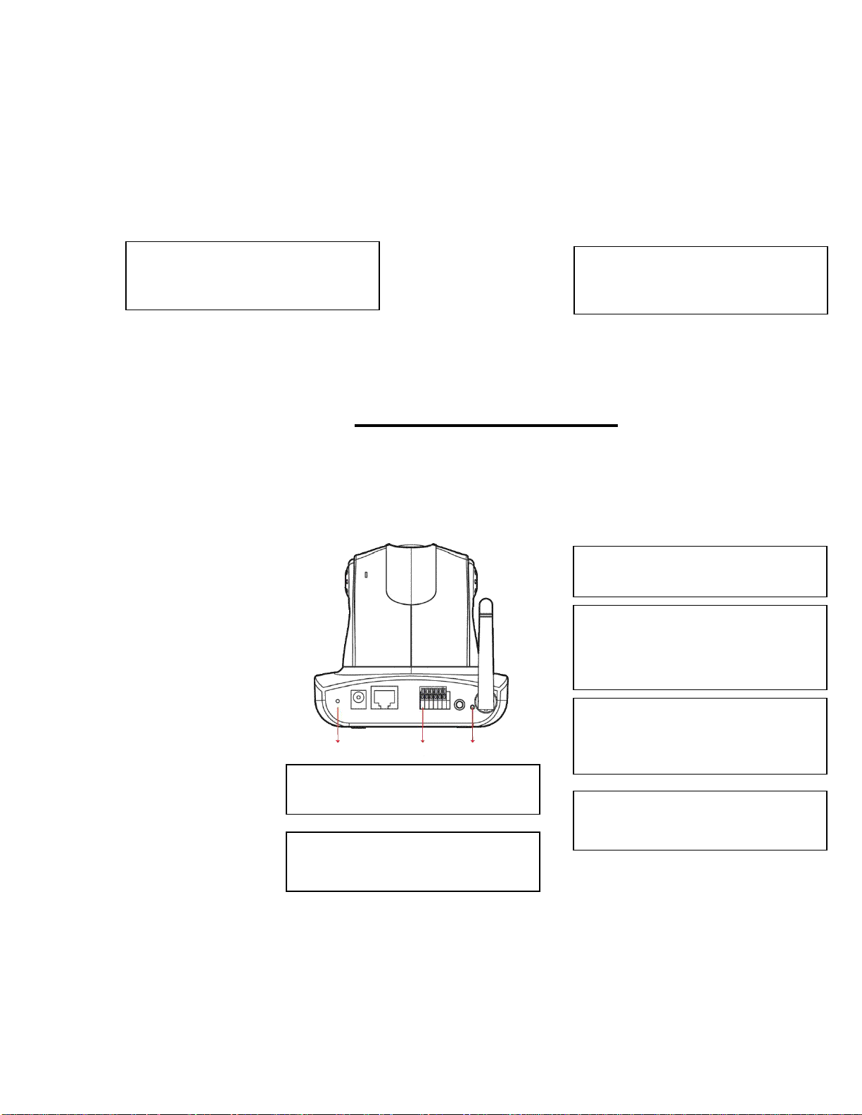
Rear Panel
o Wireless Antenna
Antenna is default to NETCAM 8001W
model only.
o I/O Terminal Block
The I/O Terminal Block connector provides
the physical interface to one relay switch
output and one digital opto-coupled input.
This block is used for receiving external
tri
ers and for controllin
o Ethernet RJ45 Jack
The RJ45 network jack is designed for 10
Mbps Ethernet and100 Mbps Fast Ethernet
network, or Power Over Ethernet and
connect to the network.
o Reset button
A button is to reset system or reset to
default manufacture setting after holding the
button for more than 5 seconds .
o Power Connector
The connector jack for DC adaptor from
NETCAM 8001.
o Embedded Microphone hole
The microphone voice receiving hole. If block
it the quality of voice reception will be
degraded.
All other names may be trademarks or registered trademarks of their respective owners. Specifications subject to change without prior notice.
©2007 Asante Networks Inc., All rights reserved. NetCam are registered trademarks of Asante Network, Inc.
10
Page 11

Tripod Mounting
The NetCam 8001 is supplied with a screw hole for tripod mounting. The screw hole is
located on the base of the unit, as shown below. The base plate of the NetCam 8001 is
similar, but is supplied with a ceiling or wall mounting plate instead of the tripod screw hole.
Wall Mounting the NetCam 8001
Ceiling Mounting the NetCam 8001
The NetCam 8001 is designed exclusively for ceiling/wall mounting and a special mounting plate is
supplied for the purpose. Screw the plate (screws not supplied) to the ceiling at the point of inst allation.
WARNING!
When installing the NetCam 8001 on the ceiling,
Please check for looseness in the camera installation mount at least once a year.
Please note that PAN degree -135° ~ 135°(Max120°/sec.) and Tilt degree -45° ~ 90° (Max120°/sec.).
Mounting Plate Information
Note: The horizontal angle is important when you hang the product from the ceiling. Excessive
inclination may bring about abnormal rotation of the camera lens.
(1) check the position of NetCam 8001 need to be vertically 90 degree even. Any non-vertical setting will cause
abnormal PAN/TILT operation.
(2) check that the ceiling is strong enough to bear the weight of the camera plus the mounting plate. A weak fitting
could result in the camera falling and causing serious injury.
3 Screw hole diameter: 6mm (1/4 in.)
Plate thickness: 1.6 mm (1/16 in.)
All other names may be trademarks or registered trademarks of their respective owners. Specifications subject to change without prior notice.
©2007 Asante Networks Inc., All rights reserved. NetCam are registered trademarks of Asante Network, Inc.
11
Page 12
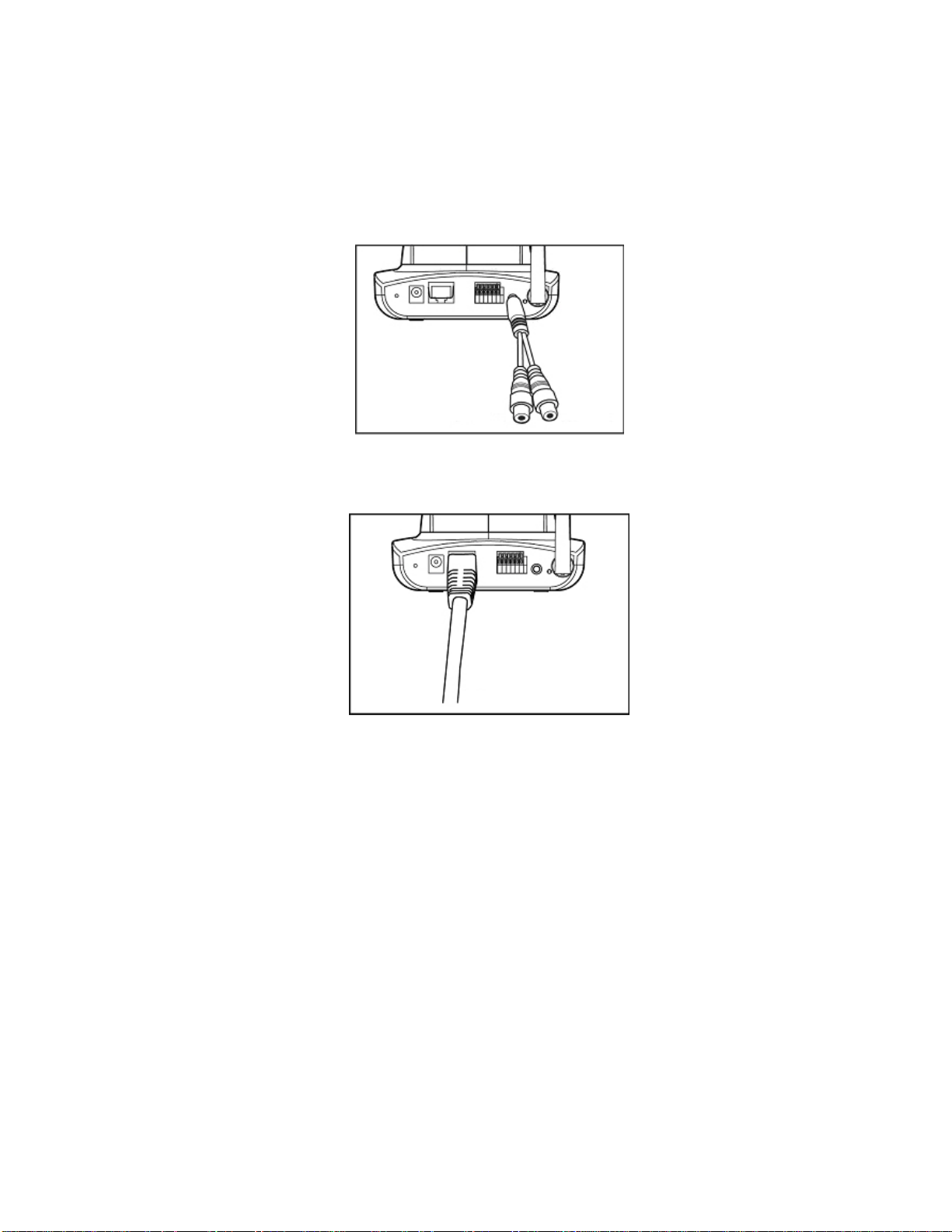
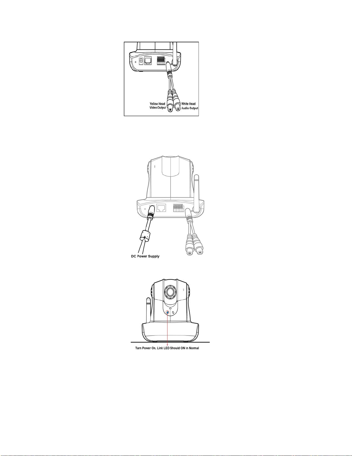
Audio/Video Output
Plug the AV converter into the audio/video output.
The yellow RCA female plug is for video output.
The white RCA female plug is for audio output.
Video
output
Audio
output
LAN Socket
Connect the LAN cable into the LAN socket.
LAN socket
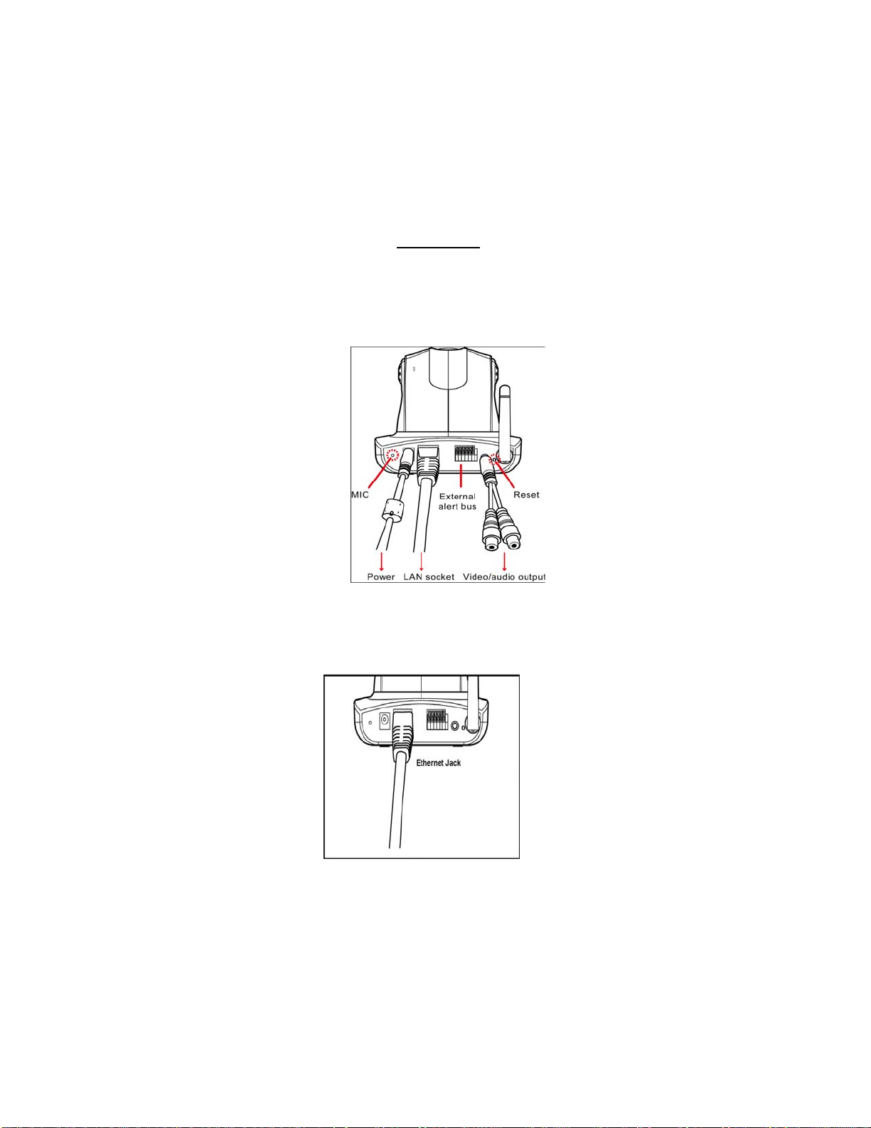
External alert bus (DI/DO)
For more information about DI/DO, refer to Attachment A.
Reset to factory settings
After turning on the power, insert a slim plastic object into the reset orifice and press for five seconds to
restore the unit to factory settings.
Built-in microphone
The product is provided with built-in microphone pickup function. Don't block this hole if you want to
use this function to acquire the best audio response.
©2007 Asante Networks Inc., All rights reserved. NetCam are registered trademarks of Asante Network, Inc.
All other names may be trademarks or registered trademarks of their respective owners. Specifications subject to change without prior notice.
12
Page 13

MIC External alert bus Reset
Link LED and Event LED
1. Link LED: The green LED lights up when you transmit images after turning on the camera.
2. Event LED: The green LED flashes when motion or alert detection is implemented after you turn
on the camera.
Focus knob
You can rotate the focus knob clockwise or anticlockwise to acquire the sharpest image. This is not
recommend to change unless you can not focus the image.
Focus knob
All other names may be trademarks or registered trademarks of their respective owners. Specifications subject to change without prior notice.
©2007 Asante Networks Inc., All rights reserved. NetCam are registered trademarks of Asante Network, Inc.
13
Page 14
4. Installing The System
Before connecting the hardware
1. Please be aware of that it is required to connect a PC and NetCam 8001 on the same IP
network or same Ethernet switch or hub for easier set up.
2. By default, NetCam 8001 is set at 192.168.0.20 private IP address.
3. Or you may use “IPFinder.exe” software come from CDROM alone with document and search
available or multiple NetCam 8001 on your network.
Wiring the Product
Connecting the hardware
1. Connect an Ethernet cable to the Ethernet connector and attach it to the network or Ethernet
switch RJ45 jack.
2. External Audio and Video could be connected to speaker and TV display respectively. Y ellow
RCA connector is video output, and white RCA connector is audio output.
All other names may be trademarks or registered trademarks of their respective owners. Specifications subject to change without prior notice.
©2007 Asante Networks Inc., All rights reserved. NetCam are registered trademarks of Asante Network, Inc.
14
Page 15
3. External Alarm DI/DO connector – Plea se refer appendix A.
4. Reset button is to reset the system back to manufacturing default setting.
5. Connect the power cable to the power supply connector and connect it to the main power
supply.
a. Upon connect the power , Pan/Tilt camera will pan back to start position and Event
indicator will show green.
6. If Ethernet has traffic pass through, the Link indicator will be flash. You can now access the
NetCam 8001 directly from your browser, as d escribed below.
(Please note, NetCam 8001W need to connect to 802.11 AP and encryption later. Please refer to
wireless setup session.)
©2007 Asante Networks Inc., All rights reserved. NetCam are registered trademarks of Asante Network, Inc.
All other names may be trademarks or registered trademarks of their respective owners. Specifications subject to change without prior notice.
15
Page 16

View or set up device via browser
System Requirements
o Windows 2000 Professional SP4 or XP Home SP2/Profession
o 256 MB Memory
o Ethernet/WLAN
o Internet Explorer 6.x or above
o VGA resolution: 800 x 600 or above
o CPU:Pentium 4 2.4 GHz or above (If you would like to monitor multiple IP camera and
record, Pentium 4 with 3GHz above or Dual Core Intel process, 1 GB Memory
and 32 MB display card are recommended)
Internet Router/Firewall Setting
How to access IP Camera form outside of LAN or Intranet
(1) Public IP address
In general, setting IP based video and voice end point device are close to the same and it
subjects to be different from router, switch, firewall and VPN environment. Please refer to
the manual to set up a static public IP address, network mask and default gateway. This is
the simplest way to bring up video device on the network.
(2) DMZ
De-Military Zone are quite popular and simple to bring up a server or device to allow
external user to access. A router normally stops incoming Internet traffic from getting
information inside the network, unless the traffic is to designate to one of your computers
and route will IP address and port forwarding the packet. But inste ad of discarding the
incoming traffic or using port forwarding, you can send incoming traffic to any device on
your network by establishing a "Default DMZ Server". (DMZ = humorous reference to
"Demilitarized Zone".) This avoids you having to figure out what ports an Internet
application wants — by throwing all ports open for that device.
Please refer to your router/firewall manual that there are hardware DMZ po rt or software
DMZ port. In the most case SOHO router , the sof tware DMZ does only allow a single device
can refer to. Thus, the network device like video server or camera need to set into an
private IP address.
After setting up complete, the viewer should be able to use router’s public IP address to
access. Please note that
(1) If you use HTTP to streaming the video – make su re there i s no se cond devic e including
router or firewall are using TCP port 80. Other wise, you have to ch ange the port to others
to differentiate from it. For example,
address is 71.6.38.188 and network device could be any available static private IP address
with port 8888 for HTTP streaming access.
(3) Port forwarding
This is a one of common programs and the ports they use for network access.
Port Forwarding can typically be used to enable similar functionality, but it is static and has
©2007 Asante Networks Inc., All rights reserved. NetCam are registered trademarks of Asante Network, Inc.
All other names may be trademarks or registered trademarks of their respective owners. Specifications subject to change without prior notice.
http://71.6.38.188:8888 is showing router ‘s public IP
16
Page 17
some limitations.
Using the Port Forwarding, you can make local computers or servers available to the
Internet for different services (for example, FTP or HTTP), to play Internet games (like
Quake III), or to use Internet applications (like CUseeMe).
Port Forwarding is designed for FTP, Web Server or other server based services like IP
Camera web server. Once port forwarding is set up, requests from the Internet will be
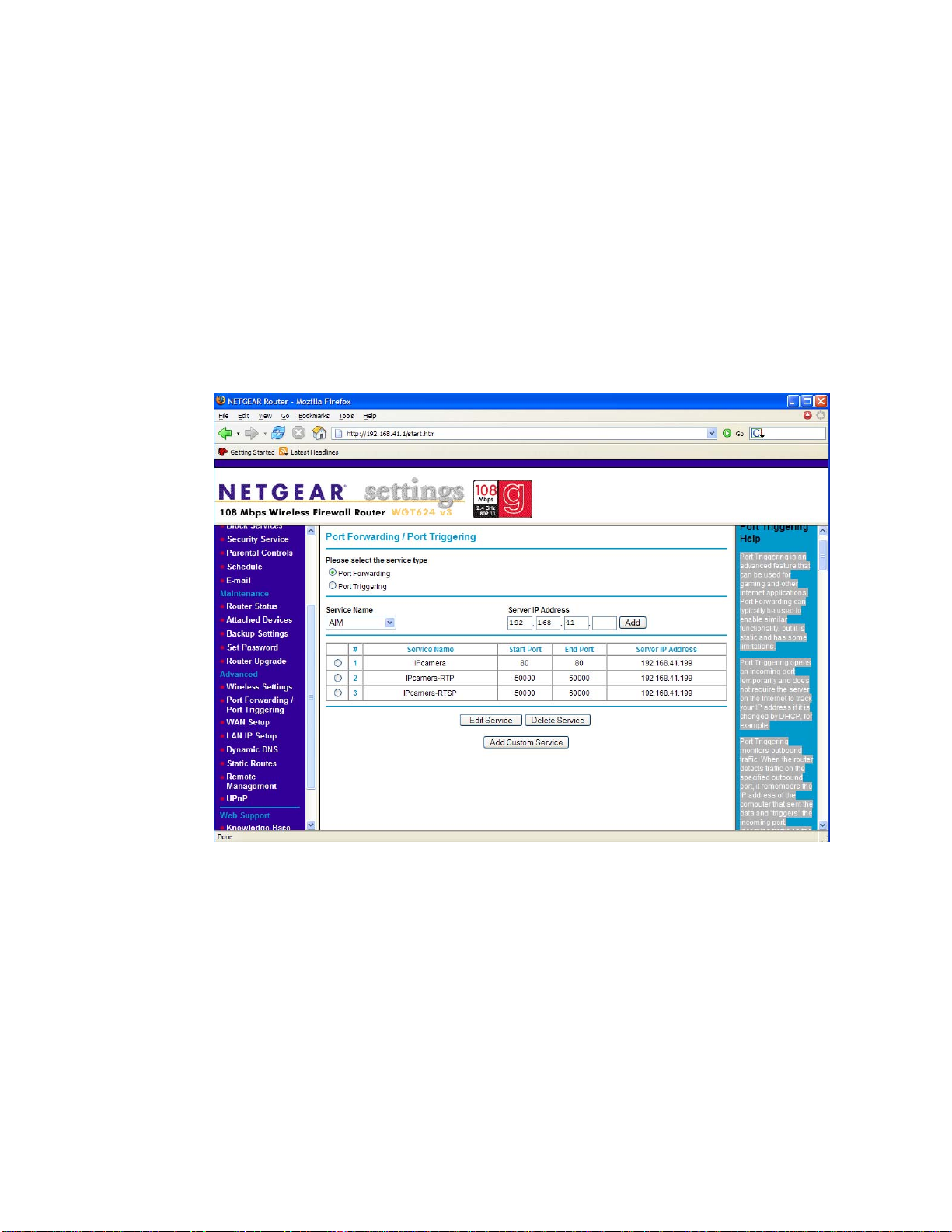
forwarded to the proper server. For example, the below is an Netgear SOHO router that
we set HTTP port 80 to forward to 192.168.41.199 which is IP camera or video server’s
private IP address. As same HTTP port 80, you may add TCP or UDP streaming transport
into the port forwarding map as well.
Change the Internet Explorer (IE) Browser Setting
1. Please be aware that the Internet security setting on router or your personal PC might block
the IP video or voice access. Please do verify the following condition.
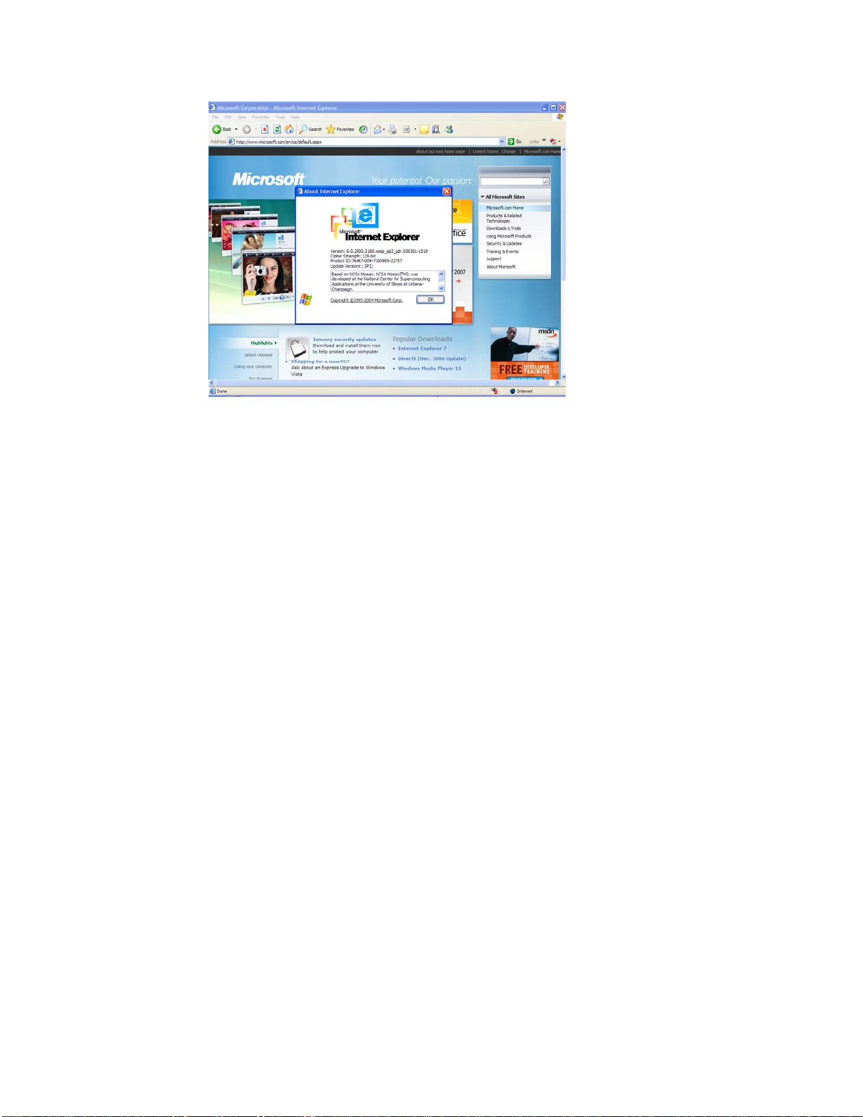
2. Verify Internet Explorer is v ersion 6.0 or above. Please go to menu and click Help and “About
Internet Explorer”’ and confirm make sure IE is version 6.0 or above.
©2007 Asante Networks Inc., All rights reserved. NetCam are registered trademarks of Asante Network, Inc.
All other names may be trademarks or registered trademarks of their respective owners. Specifications subject to change without prior notice.
17
Page 18
3. Verify Internet browser security. Click menu “tools” and “Internet Options” . Continue click tab
on “Security” and press the button on “Default Level”. If your browser is being set into
“Medium”, then you may close all pop-up windows meaning you should be able to access
video without any blocking.
4. Verify ActiveX Setting : Click IE browser’s “tools” menu, and “internet Options”. Select
“Security” and click “Customer Level” then you should see “Security Setting” pop up. Please
verify the following ActiveX related are set accordingly.
a. “Download signed ActiveXcontrols” – Please set “Prompt”
b. “Download unsigned ActiveXcontrols” – Please set “Enable”
c. “Initialize and script ActiveX controls not marked as safe” – Please set “Prompt”
d. “Run ActiveX controls and plug-ins – Please set “Enable”
e. “Script ActiveX controls marked safe for scripting” – Please set “Enable”
©2007 Asante Networks Inc., All rights reserved. NetCam are registered trademarks of Asante Network, Inc.
All other names may be trademarks or registered trademarks of their respective owners. Specifications subject to change without prior notice.
18
Page 19
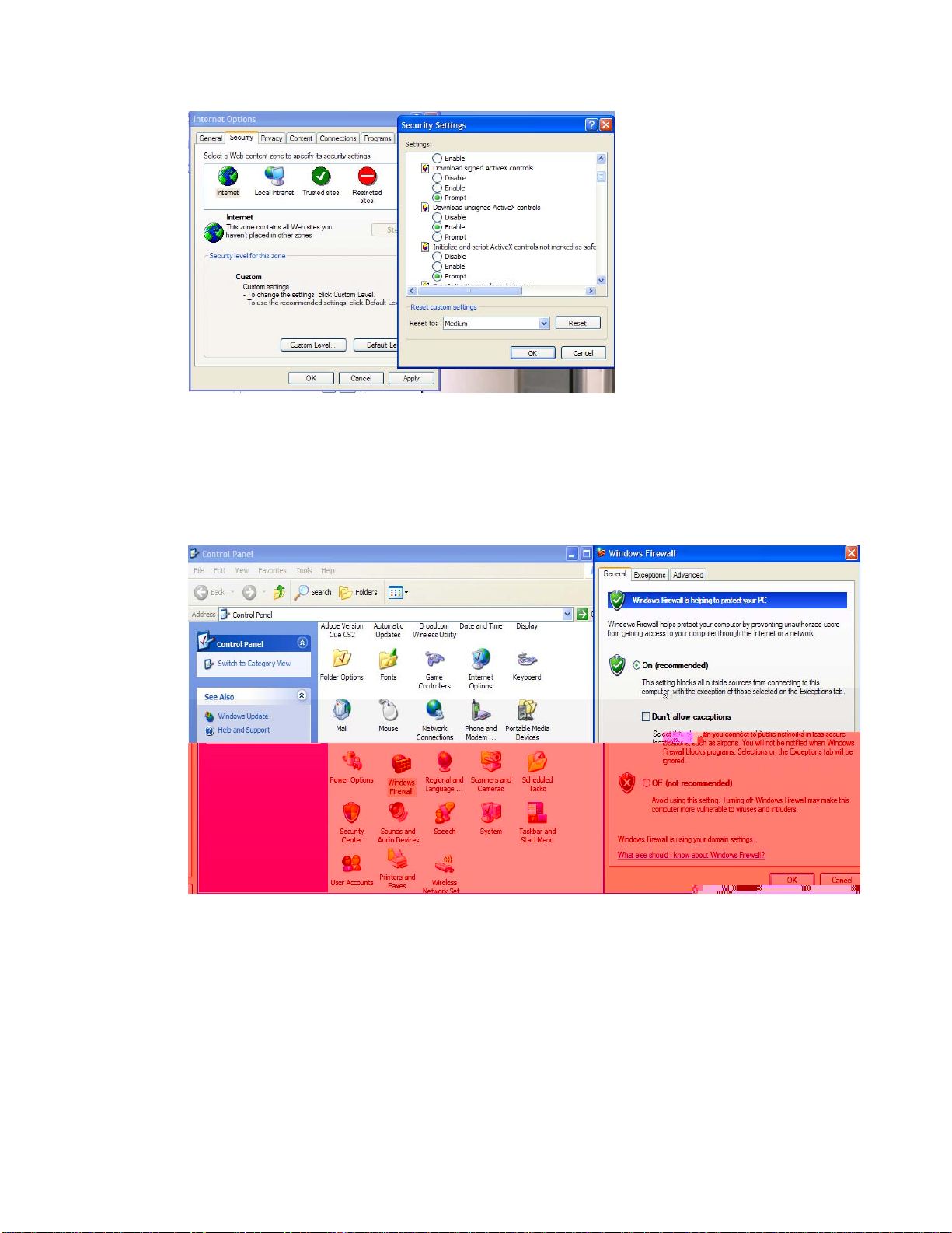
5. Verify Window Firewall Se tting. Click Control Panel and Window Firewall. If the setting is ON,
then the IP video may be blocked but in normal case the Windows may ask if you want to
unblock for temporary. It is not recommend to turn off firewall permanently in order to view the
video. It is totally user’s decision to change this setting. HTTP is the transport which normally
allow in Window Firewall.
6. “tools” and “Internet Options” . Continue click tab on “Security” and press the button on
“Default Level”. If your browser is being set into “Medium”, then you may close all pop-up
windows meaning you should be able to access video without any blocking.
©2007 Asante Networks Inc., All rights reserved. NetCam are registered trademarks of Asante Network, Inc.
All other names may be trademarks or registered trademarks of their respective owners. Specifications subject to change without prior notice.
19
Page 20
Use Internet Explorer (IE) Browser
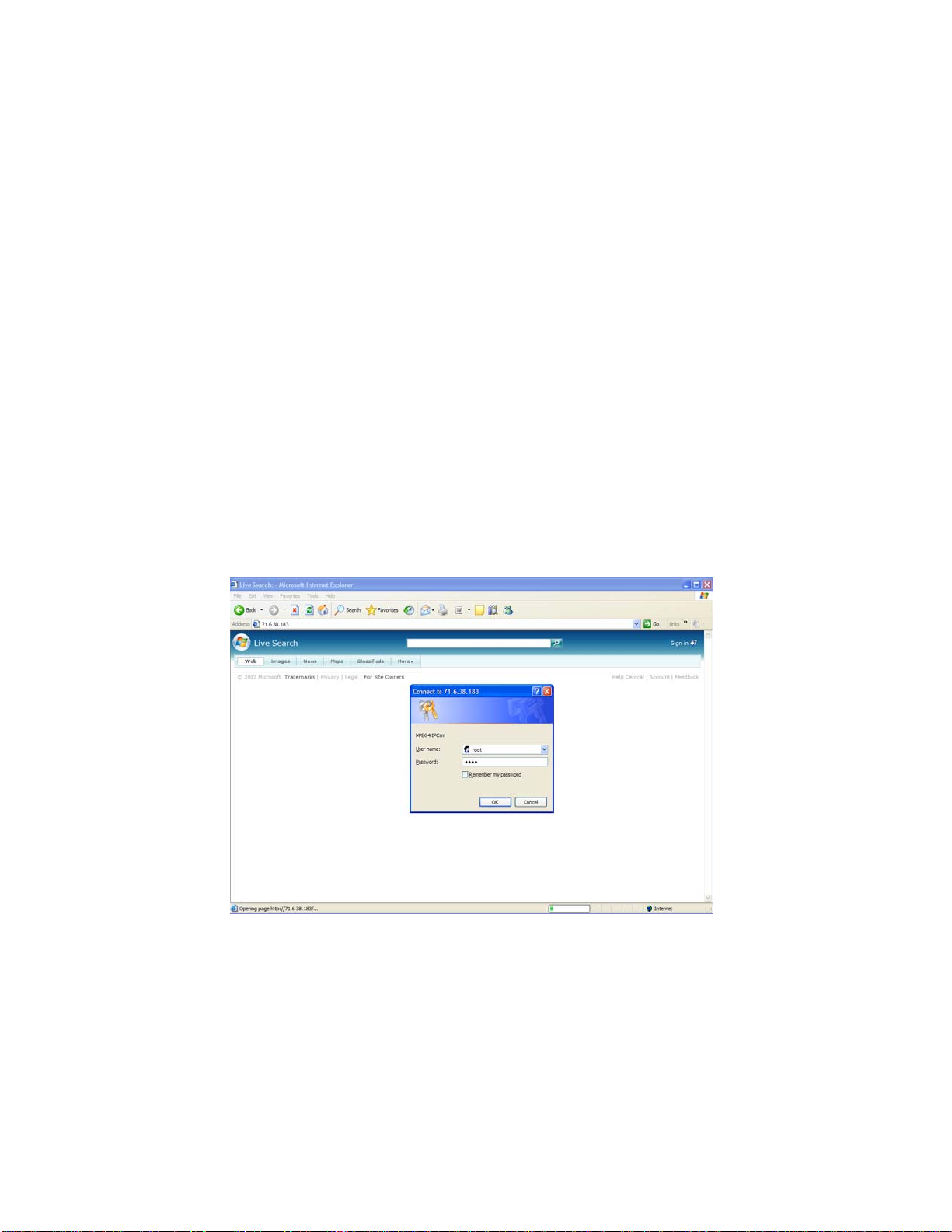
1. Start a new IE browser
2. Enter NetCam 8001 IP address and enter default username “root” with a default password
“root”.
3. You should be able to observe NetCam 8001 control panel and video. If video can not be
observed, then you may be blocked by your firewall or router. In case of this, please select
HTTP as streaming options which is the most popular available streaming transportation and
open ports for most network environment.
©2007 Asante Networks Inc., All rights reserved. NetCam are registered trademarks of Asante Network, Inc.
All other names may be trademarks or registered trademarks of their respective owners. Specifications subject to change without prior notice.
20
Page 21
All other names may be trademarks or registered trademarks of their respective owners. Specifications subject to change without prior notice.
©2007 Asante Networks Inc., All rights reserved. NetCam are registered trademarks of Asante Network, Inc.
21
Page 22
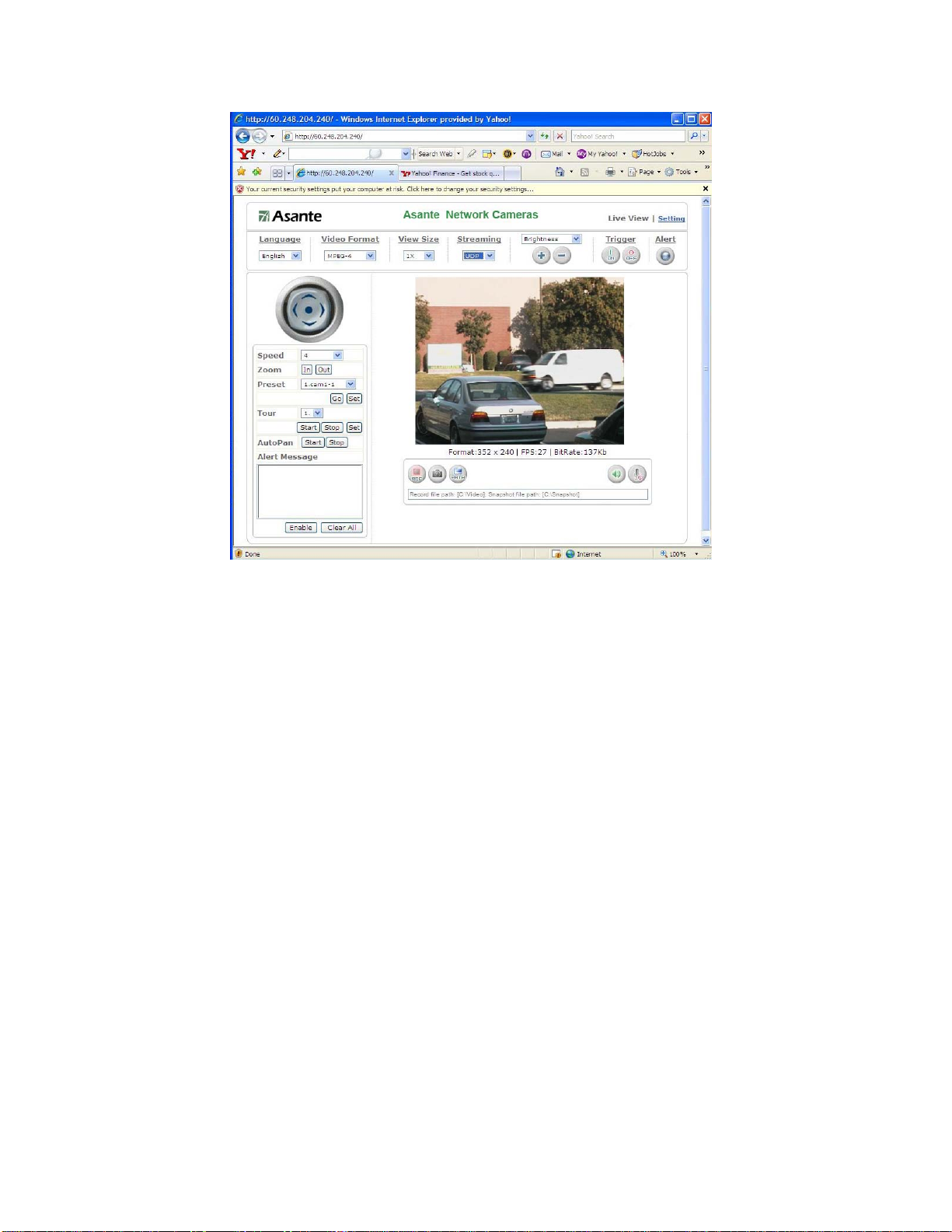
5. The Basic Operations
Web Control Features Descriptions
Main Page
Video Camera product’s main page display the video streaming from camera or video server using
TCP, UDP or HTTP transport to streaming the video to viewer, where
Under the video frame, there is text message showing source streaming is presented at 4 different
resolutions of video format.
(1) QCIF (176x120 (NTSC) or 174x144 (PAL))
(2) CIF (352x240 (NTSC) or 352x288(PAL))
(3) 4CIF (704x480 (NTSC) or 704x576(PAL))
(4) FullD1 (720x480 (NTSC) or 720x576(PAL))
FPS: Frame Per Second (from 1-30).
Bitrate: Network bandwidth available from 32K to 4096kbps and depends on device setting.
Video Format : Network Camera/Video server offers
1. MPEG4 – MPEG4 simple profile video encoding technologies
2. Motion JPEG – Motion JPEG solution will higher resolution but more cost on
network bandwidth.
Video Size : View screen can be zoom in from x1 to x4
©2007 Asante Networks Inc., All rights reserved. NetCam are registered trademarks of Asante Network, Inc.
All other names may be trademarks or registered trademarks of their respective owners. Specifications subject to change without prior notice.
22
Page 23

Streaming: Video Streaming Protocol
a. UDP (User Datagram Protocol)
UDP is non-flow control protocol and it is good for real time video voice
application. However, the UDP packet will no guarantee of delivering and
re-transmit if UDP packet loss due to the network or intermediate IP
network node congestion or service disruption.
b. TCP (Transmission Control Protocol)
Unlike UDP, it has flow control it will guarantee of delivering by giving
buffering and retransmit mechanism. This device using RTSP (Real-time
Transport Streaming Protocol) to streaming the video/audio and it is a
TCP application.
c. HTTP (Hypertext Transfer Protocol)
HTTP is WWW application protocol using TCP port 80. This is very open
to most enterprise and home router/firewall system. Leverage HTTP for
video streaming would be easier for most environments but would potential
receive more intrusion.
Brightness/Contrast:
Brightness: 0-100 adjustable
Contrast: 0-100 adjustable
Alert “ Alert light will flash in “RED” if the alert trigger condition is met. Please refer to “Event” menu
about trigger condition. This is to raise attention to staff who is monitoring the camera.
Press button again will reset the alert.
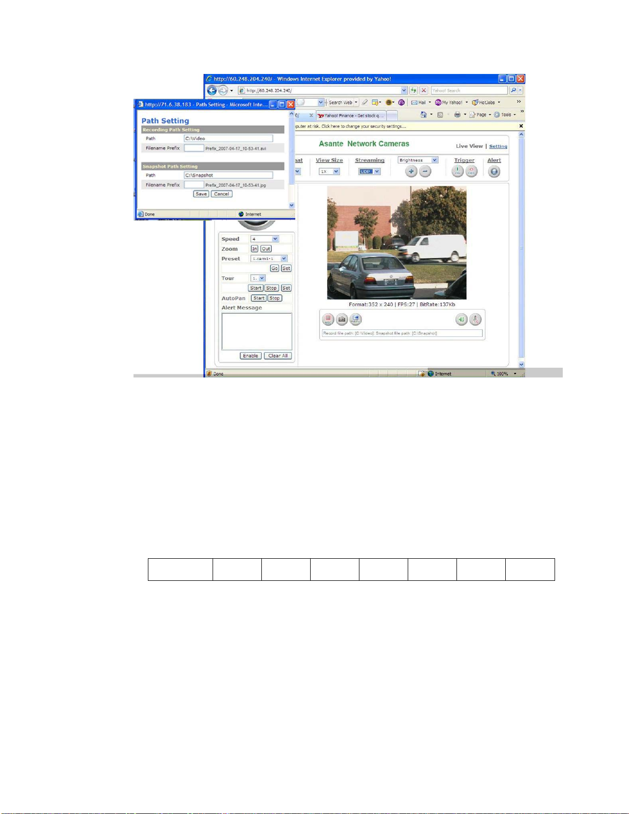
REC: “Record the video. By default, it will be stored at C:\video. You may change it at PATH
button.
SNAP shot: Real-time image capture will be stored at C:\snapshot as default. You may change it
at PATH button.
PATH: Change record or snap shot storage path at your local PC.
Audio On/Off: Enable or Disable device audio input
Microphone: Enable or Disable monitor side audio input – from PC/laptop microphone input.
All other names may be trademarks or registered trademarks of their respective owners. Specifications subject to change without prior notice.
©2007 Asante Networks Inc., All rights reserved. NetCam are registered trademarks of Asante Network, Inc.
23
Page 24
Camera Control Panel
Camera control panel offers capability of managing camera from Pan, Tilt, Preset position, or auto
Pan. The camera control wheel is able to manage the direction, speed of pan and tilt, and display
“alert message”
Control wheel: With Up, Down, Left and Right directional button to allow you to adjust the
direction.
Center button: Home position and calibration.
Speed : Scale from 1 to 7. 1 is the slowest one and 7 is the fastest.
Speed 1 2 3 4 5 6 7
Angel/Sec 3 20 40 60 80 100 120
Zoom: Zoom could be Zoom In or Zoom Out on camera. If camera has zoom capability, it will
control zoom motor. If camera has no zoom capability, the digital zoom will be applied as
default.
Preset : Device could have 16 position with capability to naming the position so that you can
expedite the camera pan/tilt by one button. Procedure described as follow:
1) Select SET, a sub window will popup
2) Select Location Number from sub windows and enter the position name.
3) Control camera wheel to desire location for this position identity
4) Click “Update” and “exit”.
5) You may test by select number on control panel and press “go”. Camera will speedy
to turn to that location you set easier.
All other names may be trademarks or registered trademarks of their respective owners. Specifications subject to change without prior notice.
©2007 Asante Networks Inc., All rights reserved. NetCam are registered trademarks of Asante Network, Inc.
24
Page 25

Tour : Device could be arranged by automatically “touring” each “preset location” with still stand
at that location for a dwelling timer. The timer is configurable. Procedure describes as
follow:
1) Select SET, a sub window will popup
2) Select Location Number from sub windows and enter the position name.
3) Control camera wheel to desire location for this position identity
4) Click “Update” and “exit”.
5) You may test by select number on control panel and press “go”. Camera will speedy
to turn to that location you set easier.
AutoPan: Device could be paned automatically from left to right and right to left until you disable
it.
Alert Message: Enable/Disable button is to enable or disable alert me ssage (Max 50 message).
When you leave this page, the alert messages will not be saved. Detail alert message,
please refer to setting-=>application setting-=>event.
Save AlertingImg: Enable/Disable button is to enable or disable save alert image to the directory
of SNAPSHOT defined at Path.
Please refer to Setting/Application Setting/Event/Event for more detail.
©2007 Asante Networks Inc., All rights reserved. NetCam are registered trademarks of Asante Network, Inc.
All other names may be trademarks or registered trademarks of their respective owners. Specifications subject to change without prior notice.
25
Page 26

6. Setting Page
System :
System Info
Device Name - Any Device Name should be entered without any space.
MAC address – Network Camera/server Ethernet Media Access Control (MAC) address.
IP address – Network Camera/server Internet Protocol (IP) address.
Network Mask – IP address network mask for subnetwork setting
Gateway – LAN or WAN to external IP address
Current Viewers – Counter for viewers
Firmware Build Time - Firmware Releas e date
Firmware Build Number - Firmware Release date
Firmware Version – Device Firmware version
Current Viewer: number of viewer
Event LED:
ON/Flash : any event trigger
OFF: Turn off the LED
Link LED:
ON/Flash : Any streaming flow through network
All other names may be trademarks or registered trademarks of their respective owners. Specifications subject to change without prior notice.
©2007 Asante Networks Inc., All rights reserved. NetCam are registered trademarks of Asante Network, Inc.
26
Page 27

OFF: Turn off the LED
System Log :
Administrator can understand the usage on this device including ON and OFF device,
streaming viewer, Login users and time.
Video/Image :
Network Camera/server system log
Video image configuration
Vide/Image: 3GPP
To view the camera image using a 3G cellular phone, click Enable to enable the 3GPP mode.
(Note: When the 3GPP mode has been activated, all relevant para meters are set
automatically and cannot be changed. .This is for the reason of compatibility).
Please refer to your 3G service provider to conduct all necessary setting.
To use the 3GPP function, the following requirements must be met. Contact your telecom
company
to learn more about the connection conditions):
1. 3G phone: Your cellular phone functions properly and supports 3G se rvice. The
compatible cellular phones that have passed our test are: Nokia 6630, No kia N73, Wibo
WinII, Nokia E61, Nokia N70, Nokia N93
2. 3G phone number is available.
3. The 3G wireless networking service is available.
©2007 Asante Networks Inc., All rights reserved. NetCam are registered trademarks of Asante Network, Inc.
All other names may be trademarks or registered trademarks of their respective owners. Specifications subject to change without prior notice.
27
Page 28

4. The camera has a fixed IP address.
5. The 3GPP mode is activated.
Example : Nokia N71. Follow these steps to set up your 3G viewing function.
All other names may be trademarks or registered trademarks of their respective owners. Specifications subject to change without prior notice.
©2007 Asante Networks Inc., All rights reserved. NetCam are registered trademarks of Asante Network, Inc.
28
Page 29

Vide/Image: Video Format
You can select MPEG4 or MJPEG as the video format. It is recommended to select MPEG4
for real-time browsing to optimize the bandwidth. MJPEG is a good choice for the best
resolution when video recording is required for collection of evidence.
Video Image: Video Resolution
Generally speaking, selection of resolution is depending on the bandwidth of the network you
can afford. This product of fers different selections for video/audio settings. However, to ensure
video flow rate sustaining, you need a higher uploading band width. Generally, it is
recommended to use CIF resolution for remote access using DSL or cable modem bandwidth
capacity. To meet other requirements, refer to Attachment B for more information. Please note,
the higher resolution the higher bandwidth. If you overrun your network bandwidth, the low
frame rate and disrupted frame picture will be observed.
Video Resolution: PAL/NTSC
1. D1(704x576 / 704x480)
2. VGA(640x480)
3. CIF(352x288 / 352x240)
4. QCIF(176x144 /176x112)
All other names may be trademarks or registered trademarks of their respective owners. Specifications subject to change without prior notice.
©2007 Asante Networks Inc., All rights reserved. NetCam are registered trademarks of Asante Network, Inc.
29
Page 30

Video Image: Frame Per Second (FPS)
Frame per Second (FPS): Frames per second to stream on the network
NTSC have 30, 15, 10, 7, 6, 5, 4, 3, 2, frame rates selection
PAL have 25, 12, 6, 5, 4, 3, 2, 1 frame rates selection
Video Image: Video Quality
Video quality subjects to be determined by the quality of each image frame or quality of
consecutive video motion which we offer. When you select this, the bandwidth will be variable bit
rate and depends of the motion changing. The higher motion the higher bandwidth is required.
©2007 Asante Networks Inc., All rights reserved. NetCam are registered trademarks of Asante Network, Inc.
All other names may be trademarks or registered trademarks of their respective owners. Specifications subject to change without prior notice.
30
Page 31

Fix Quality: Device will perform best effort in the quality level of
1. Best
2. Better
3. Normal
4. Fast
5. Fastest
Fix Bit Rate: This device offers 15 different rates, Higher the bandwidth you select, the better and
smooth video quality will be delivered. This is a constant bit rate quality which the video
will be within the range of bandwidth you select.
All other names may be trademarks or registered trademarks of their respective owners. Specifications subject to change without prior notice.
©2007 Asante Networks Inc., All rights reserved. NetCam are registered trademarks of Asante Network, Inc.
31
Page 32

Video Image: GOP (Group Of Pictures)
GOP provides users with the function to set the pages of the I Frame and P Frame to be
transmitted in the MPEG4 mode. Basically, the I Frame page contains the entire picture and
needs higher bandwidth, while the P Frame pag e only cont ains the part s that are dif ferent from
the I Frame and needs lower bandwidth. Hence, when you need to transmit the pages without
disruption in a normal network environment, you can set up a higher GOP. For example, if
GOP 25 is selected, 24 P Frame pages will follow 1 I Frame page, and so forth. However,
packets may be lost when they are transmitted in a congested network environment. In this
case, the following P Frame pages may bring about disruption of the transmission because
they lose the reference upon which the difference from the I Frame is identified. You may
change GOP to 10 with this concern to a void disruptio n of the transmissi on. The GOP is 15 by
default.
Video Image: OSD
You can set to display the date, camera name and other information on the screen.
Video Image: OSD: Display Mode
You can select to display the date (Date), time (Time) or text (Text).
Video Image: OSD: Display Text
You can key in the text to be displayed on the screen (Ex.: Lobby IP Cam)
Video Image: OSD: Display Color
256 colors and tones from 0 (deepest black) to 255 (lightest white) are available for display of
the text.
Video Image: OSD: Sensor (Brightness/contrast adjustment)
Video Image: OSD: Sensor : Brightness
Brightness: Adjustable between 0~100
Video Image: OSD: Sensor : Contrast
Contrast: Adjustable between 0~100
Or it could be adjusted at front panel.
All other names may be trademarks or registered trademarks of their respective owners. Specifications subject to change without prior notice.
©2007 Asante Networks Inc., All rights reserved. NetCam are registered trademarks of Asante Network, Inc.
32
Page 33

Audio:
Audio Setting:
Audio Raw Format: Audio Codec (No or 16bit PCM)
©2007 Asante Networks Inc., All rights reserved. NetCam are registered trademarks of Asante Network, Inc.
All other names may be trademarks or registered trademarks of their respective owners. Specifications subject to change without prior notice.
33
Page 34

User Setting
User List:
Add – Add user by setting Username, Password, and Privilege.
A table for user privilege format:
©2007 Asante Networks Inc., All rights reserved. NetCam are registered trademarks of Asante Network, Inc.
All other names may be trademarks or registered trademarks of their respective owners. Specifications subject to change without prior notice.
34
Page 35

User Administrator operator viewer
Live View v v v
System Setting v v
Video Setting
Audio Setting v v
Date / Time Setting v
User Setting root
Network Setting
IP Filter setting
Event Setting
Motion Setting v v
Firmware Upgrade root
Factory default v
v v
3GPP v v
v
Wireless v
DDNS setting v
PPPoE setting v
Streaming v
UPnP v
SMTP v
SAMBA v
Notification v
v
v v
schedule setting v v
event server v v
trigger setting v v
Delete: Remove current user. Please note that “root” user can not be removed.
User Setting:
Anonymous login: Allow a nonymous log in
Anonymous PTZ control: Allow user control PTZ
Maximum number of simultaneous viewers: Maximum of concurrent viewers.
©2007 Asante Networks Inc., All rights reserved. NetCam are registered trademarks of Asante Network, Inc.
All other names may be trademarks or registered trademarks of their respective owners. Specifications subject to change without prior notice.
35
Page 36

Network:
IP Assignment
DHCP: Dynamic Host Configuration Protocol.
Default is OFF. Factory preset IP address as 192.168.0.20.
DHCP setting will issue DHCP request to any available DHCP server in your network
environment. On the return, you will receive a “legal” IP address, Subnet mask, Default
gateway, DNS 1, DNS 2:
DNS: system can not run without a correct DNS, particular to the SMTP mail, and DDNS
service.
Wireless Setting:
Wireless
AP Information
Wireless network Camera do allow you to search available wirel ess AP(Access Point) near th e
network camera device. The default will scan after you switch to this page or you may scan
again to search the update AP.
All other names may be trademarks or registered trademarks of their respective owners. Specifications subject to change without prior notice.
©2007 Asante Networks Inc., All rights reserved. NetCam are registered trademarks of Asante Network, Inc.
36
Page 37

From the AP informatio n t able, you can find out the SSID, Mode, Channel, Encryp tion, Quality,
and MAC address, where SSIS is the only item you need to select to configure network
wireless setting. Encryption is required to be identical to AP encryption setting. Please consult
your IT manager to acquire the Encryption Key information and at least one key is required.
Mode:
Infrastructure: WALN Infrastructure I sunder WLAN AP or bridge AP network mode.
AdHoc: A P2P allows wireless devices to directly communicate with each other. Wireless
devices within range of each other can discover and communicate directly without involving
central access points. This method is typically used by two computers so that they can
connect to each other to form a network.
Mode: Selection of the wireless networking mode
1. Infrastructure: Infrastructure networking mode
This camera uses the wireless Access Point (AP) as the hub when set to infrastructure
networking mode and connects to the network via the wireless AP.
©2007 Asante Networks Inc., All rights reserved. NetCam are registered trademarks of Asante Network, Inc.
All other names may be trademarks or registered trademarks of their respective owners. Specifications subject to change without prior notice.
37
Page 38

WORKSTATION1
WORKSTATION 2
AdHoc networking mode
2. AdHoc: Point-to-point networking mode
This camera connects to other wireless devices via a wireless network when it is in the
AdHoc point-to-point networking mode; i.e. the product connects to other devices equipped
with built-in wireless connection function without the need to access from any AP.
Note: Where no IP address is assigned from the DHCP server, the system will set the
Link-Local Address automatically. However, it is not routable IP address in most
environments.
Note: Wireless LAN is very popular today, please note that user use the network camera is
recommended to use
subject to depend on the wireless signal strength from the location where network connect to
AP, building block signal, and all wireless traffic in single AP. All factors will significant impact
the quality for realtime streaming data such as video.
Unlike wired 100M/1000M Ethernet point to point throughput which give you a lot of
bandwidth room to use. Although WLAN technologies claims to have 54Mbps throughput, is
it a share bandwidth and condition usage network. Therefore, 1.5Mbps and 60% of signal
strength or higher are highly recommend. Above that bandwidth or low signal strength will
result packet loss, low frame rate, distort video image. Or you have to lower the frame rate,
video size or bandwidth.
Authentication Type:
Open System Authentic ation
Open system authentication simply consists of two communications. The first is an
authentication request by the client that contains the station ID (typically the MAC address).
This is followed by an authentication response from the AP/router containing a success or
failure message.
“1.5Mbps” or below bandwidth due to wireless connectivity’s are
All other names may be trademarks or registered trademarks of their respective owners. Specifications subject to change without prior notice.
©2007 Asante Networks Inc., All rights reserved. NetCam are registered trademarks of Asante Network, Inc.
38
Page 39

Shared Key Authentication
Shared key authentication relies on the fact that both stations t aking p art in the authentication
process have the same "shared" key or pass ph rase. T he shared ke y is manually set on b oth
the client station and the AP/router. Th ree types of shared key authentication are available
today for home or small office WLAN environments.
SSID: An SSID is the public name of a wireless network. You will use this to connect a
trusted wireless AP.
Wired Equivalent Privacy (WEP)
The process consists of an authentication request from the clie nt, clear challeng e text from the
AP/router, encrypted chall enge text from the client and an authentication response from the
AP/router. Two levels for WEP keys/pass phrases:
1. 64-bit: 40 bits dedicated to encryption and 24 bits allocated to Initialization Vector (IV). It
may also be referred to as 40-bit WEP.
2. 128-bit: 104 bits dedicated to encryption and 24 bits allocated to Initializatio n Vector
(IV). It may also be referred to as 104-bit WEP.
WEP security mode: Select an encryption mode from the list. The format is “None” by default,
indicating that the security function is disabled.
Authentication mode: One of the following authentication modes is required when you select
a WEP encryption mode from the security list.
1. 64 Bit (10 Hex chars)
2. 64 Bit (5 ASCII chars)
3. 128 Bit (26 Hex chars)
4. 128 Bit (26 ASCII chars)
WEP key password encryption mode:
You can set up 64 Bit or 128 Bit WEP key password encryption mode. A set of 64 Bit
encryptions is equivalent to 10 sets of hexadecimal digits or 5 sets of ASCII characters. A set
All other names may be trademarks or registered trademarks of their respective owners. Specifications subject to change without prior notice.
©2007 Asante Networks Inc., All rights reserved. NetCam are registered trademarks of Asante Network, Inc.
39
Page 40

of 128 Bit encryptions is equivalent to 26 sets of hexadecimal digits or 13 sets of ASCII
characters.
Encoding HEX ASCII Available characters 0~9, a~f, A~F 0~9, a~f, A~Z 64 Bit 10 5 128 Bit 26 13
Example.: Wireless mode setting (applicable to most situations)
Selection:
1. Mode: Select Infrastructure to connect the camera to a wireless base station.
2. Authentication Type: Select Shared Key.
3. SSID: Enter the server name of the base station.
4. WEP Encryption: Select the encrypted key that is the same as the base station.
5. KEY: Select a group that is the same as the wireless base station. You must select
KEY1 for base stations that only have a set of keys.
6. DHCP ON/OFF: DHCP ON is recommended.
7. Save the settings.
Restart the equipment.
Wireless IP Assignment:
DHCP: Dynamic Host Configuration Protocol.
©2007 Asante Networks Inc., All rights reserved. NetCam are registered trademarks of Asante Network, Inc.
All other names may be trademarks or registered trademarks of their respective owners. Specifications subject to change without prior notice.
40
Page 41

Default is OFF. Factory preset IP address as 192.168.0.20.
DHCP setting will issue DHCP request to any available DHCP server in your network
environment. On the return, you will receive a “legal” IP address, Subnet mask, Default
gateway, DNS 1, DNS 2:
Streaming
1. HTTP: HTTP is WWW application protocol using TCP port 80. This is very open to
2. RTSP: TCP Port 554 as default. it has flow control it will guarantee of delivering by
3. RTP: UDP Port 50000 ~ 60000 as default. UDP is non-flow control protocol and it is
most enterprise and home router/firewall system. Leverage HTTP for video streaming
would be easier for most environments but woul d potential receive more intrusion.
giving buffering and retransmit mechanism. This device using RTSP (Real-time
Transport Streaming Protocol) to streaming the video/audio and it is a TCP
application.
good for real time video voice application. However, the UDP packet will no guarantee
of delivering and re-transmit if UDP packet loss due to the network or intermediate IP
network node congestion or service disruption.
PPPoE
PPPoE: Point-to-Point Protocol over Ethernet, is a network protocol for encapsulating PPP
frames in Ethernet frames. It is used mainly with ADSL services. It offers standa rd PPP feature s
such as authentication, encryption, and compression. Unfortunately it has an MTU lower than
that of standard Ethernet which can sometimes cause problems with badly configured firewalls.
©2007 Asante Networks Inc., All rights reserved. NetCam are registered trademarks of Asante Network, Inc.
All other names may be trademarks or registered trademarks of their respective owners. Specifications subject to change without prior notice.
41
Page 42

PPPoE is a tunneling protocol which allows layering IP, or other protocols that run over PPP,
over a connection between two Ethernet ports, but with the softwa re features of a PPP link, so it
is used to virtually "dial" to another Ethernet machine and make a point to point connection with
it, which is then used to transport IP packets, based on the features of PPP.
It allows the use of traditional PPP-based software to handle a connection which does not use a
serial line, but a packet-oriented network like Ethernet, to provide a classical connection with
login and password for Internet connection accounting. Also, the IP address on the other side of
the link is only assigned when the PPPoE connection is open, allowing the dynamic reuse of IP
addresses.
All other names may be trademarks or registered trademarks of their respective owners. Specifications subject to change without prior notice.
©2007 Asante Networks Inc., All rights reserved. NetCam are registered trademarks of Asante Network, Inc.
42
Page 43

Network: PPPoE (dial-up networking setting)
PPPoE: Point-to-Point Protocol over Ethernet is a protocol that supports access to a
high-speed wideband network using a PC and a wideband modem (such as xDSL, Cable,
Wireless modem). The user need only to equip the PC with an Ethernet card and apply to
an ISP (such as HiNet) and an ADSL provider (such as Chunghwa Telecom) for ADSL
service to roam the Internet through ordinary twisted copper wires.
PPPoE: Point to Point Protocol over Ethernet is applicable to networking via a xDSL or
cable modem. PPPoE setting must be executed in the LAN environment for your PC to
connect to ADSL. Follow the steps below to complete the setting:
1. Dial: You can select whether or not to dial when you boot the machine.
2. Use DHCP or fixed IP for connection to the LAN environment.
3. Key in the IP address of the camera and enter "PPPoE Setting" following the route
Setting Basic Setting Network PPPoE.
4. Key in the xDSL "Username" and "Password" acquired from your ISP. Click Save to
confirm the setting.
5. Where the ADSL modem and the camera is connected via a switch-hub, you can
press “Reboot” or restart the machine manually to try PPPoE dialing when the setting
of the camera has been completed.
6. To observe the new IP address acquired when PPPoE dialing has been executed
successfully, follow the route Setting Basic Setting NetworkNotification for the
IP information. You can acquire the new IP address via SMTP, FTP, and HTTP. Refer
to the “Notification Setting” page for more information.
Note: You can use the DDNS function to access the camera. Refer to the “DDNS Setting” page
for more information.
©2007 Asante Networks Inc., All rights reserved. NetCam are registered trademarks of Asante Network, Inc.
All other names may be trademarks or registered trademarks of their respective owners. Specifications subject to change without prior notice.
43
Page 44

Network: PPPoE: PPPoE
Dial: You can select whether or not to dial when you boot the machine (On Boot or Off).
Username: Enter the username provided by your ISP.
Password: Enter the password.
Network: PPPoE: PPPoE Information
IP Address: The IP address acquired when dialing has been executed successfully.
Subnet Mask: The subnet mask information acquired when dialing has been executed
successfully.
Default Gateway: The gateway information acquired when dialing has been executed
successfully.
DNS: The ISP domain name acquired when dialing has been executed successfully.
All other names may be trademarks or registered trademarks of their respective owners. Specifications subject to change without prior notice.
©2007 Asante Networks Inc., All rights reserved. NetCam are registered trademarks of Asante Network, Inc.
44
Page 45

DDNS
DDNS: Dynamic Domain Name Server
DDNS is a service that maps Internet domain names to IP addresses. DDNS serves a similar
purpose to DNS: DDNS allows anyone hosting a Web or FTP server to adverti se a public
name to prospective users.
Unlike DNS that only works with static IP addre sses, DDNS works with dynamic IP addresses,
such as those assigned by an ISP or other DHCP server. DDNS is popular with home
networkers, who typically receive dynamic, frequently-changing IP addresses from their
service provider. To use DDNS, one simply signs up with a provider and installs network
software on their host to monitor its IP addres s.
The service of DDNS on the Internet including www.no-ip.com and www.DynDNS.org.
Please note that some of gateway or router may register to DDNS, thus end point device sit
behind the router or gateway may not need to set the DDNS information.
Active: DDNS(Enable) or (Disable)
DDNS Server: Current support only
http://dyndns.org. This is a free service.
Network: DDNS (Dynamic Domain Name Server Setting)
The IP address (for example 210.168.0.22) is like a telephone number, while the website
address is like a name in an address book. The DDNS allows the user to access the website
by entering the name of the website without memorizing a bunch of cold numbers.
When you apply for an Internet service, you will have at least one IP address from your ISP
that is either fixed or dynamic. Most of the ADSL service providers will give you a dynamic IP
for ADSL environments, which means your IP address will constantly change each time you
connect to the Internet. As a result, users from WAN environments will have much difficulty
finding the correct IP address. The DDNS (Dynamic DNS service) is created for exactly this
kind of moment. By updating your WAN IP address each time you connect to the Internet, the
All other names may be trademarks or registered trademarks of their respective owners. Specifications subject to change without prior notice.
©2007 Asante Networks Inc., All rights reserved. NetCam are registered trademarks of Asante Network, Inc.
45
Page 46

DDNS helps you locate your website and access your website easily. You can find a lot of free
DDNS service providers on the Internet, such as www.no-ip.com and
Some gateway-routers can directly communicate with DDNS. In this case, you may directly
enter your DDNS account on the setting page in the Internet router, and then the router will
update your WAN IP status whenever it is changed and report to the DDNS. If your router
does not support direct communication with the DDNS, you can download a small application
program on the DDNS service page to help you update your WAN IP.
www.DynDNS.org.
Item Description:
Active: enables/disables DDNS
DDNS Server: currently we only support
provided by DynDNS. You may log on this website for relevant information and apply for free
domain names.
Username: your account for the domain name you applied for
Password: your password for the domain name you applied for
Domain Name: the domain name you applied for.
http://dyndns.org. This is a free domain name server
All other names may be trademarks or registered trademarks of their respective owners. Specifications subject to change without prior notice.
©2007 Asante Networks Inc., All rights reserved. NetCam are registered trademarks of Asante Network, Inc.
46
Page 47

UPnP: Universal Plug and Play
UPnP Device
If you connect your camera to a router, IP allocator, or wireless AP, your camera will possibly
be blocked by the NAT and can’t be located on the Internet. To penetrate the firewall, activate
the supportive item- UPnP. The Link URL shows the external IP address and the port of the
router. Enter the IP address in the Internet Explorer to penetrate the NAT.
UPnP (Universal Plug and Play)
If you connect your camera to a router, IP allocator, or wireless AP, your camera will possibly
be blocked by the NAT and can’t be located on the Internet. To penetrate the firewall, activate
the supportive item- UPnP. The Link URL shows the external IP address and the port of the
router. Enter the IP address in the Internet Explorer to penetrate the NAT.
Network: UPnP: UPnP Device
Active: yes (enable)/no (disable)
Device Name: the name of the UPnP device
Network: UPnP: UPnP Traversal
Active: yes (enable)/no (disable)
Port Range: the range of the usable ports, from 32768 to 65535 as default
Link URL: Uniform Resource Locator, the web address
Click “Save” to confirm when you finish.
UPnP setting
©2007 Asante Networks Inc., All rights reserved. NetCam are registered trademarks of Asante Network, Inc.
All other names may be trademarks or registered trademarks of their respective owners. Specifications subject to change without prior notice.
47
Page 48

To activate the UPnP function in Windows OS:
For example : Windows XP:
1. Windows component installation.
2. Open Windows firewall option
2. View the connection device using “My Network Place”
©2007 Asante Networks Inc., All rights reserved. NetCam are registered trademarks of Asante Network, Inc.
All other names may be trademarks or registered trademarks of their respective owners. Specifications subject to change without prior notice.
48
Page 49

SMTP Server
SMTP server is to set for alarm triggering report via email format. When the criteria or
condition match on event from motion detection or alarm I/O or manual trigger, the image will
be captured and email to the destination accordingly.
SMTP server: Setting SMTP server IP address or domain name address – for example
SMTP From: Sender mail address – for example xxx@xxx.com. It is to notice recipient the
sender information.
SMTP Authentication: enable or disable to verify the login security.
Username: enter user valid account name (in most case, you do not need to put “@xxx.com”)
Password: enter user valid password
Select “SAVE” to save the setting.
mail.comcast.net or your ISP available SMTP server. Please note that SMTP is
support only regular standard access using TCP port 25. If you are not using IP
address for specify the SMTP server, your DNS server need to set correctly so
that SMTP name resolution to IP could be successful.
All other names may be trademarks or registered trademarks of their respective owners. Specifications subject to change without prior notice.
©2007 Asante Networks Inc., All rights reserved. NetCam are registered trademarks of Asante Network, Inc.
49
Page 50

Samba
Samba is software that can be run on a platform other than Microsoft Windows, for example,
UNIX, Linux, IBM System 390, OpenVMS, and other operating systems. Samba uses the
TCP/IP protocol that is installed on the host server. It allows that host to interact with a Microsoft
Windows client or server as if it is a Windows file and print server.
This device offer a capability to seamlessly access external share file system which is not
managed by Linux such as Windows Operating System, Network Access Storage(NAS) or
Network Video Recorder(NVR).
To configure this IP surveillance device to store alarm video/image to a larger or secure or
backup file system. You may activate as follows:
Active: enable or disable
SMTP setting
Network
Camera
Network
Access
Storage
Browser
Samba Authentication: enable or disable the security access
©2007 Asante Networks Inc., All rights reserved. NetCam are registered trademarks of Asante Network, Inc.
All other names may be trademarks or registered trademarks of their respective owners. Specifications subject to change without prior notice.
50
Page 51

Username: enter external file system account user name. (For NAS, please refer to NAS user
manual to create user name and password).
Password: enter external file system account password.
Path: Enter the full path of destination to store your information in format of IP address and
directory in the format as
xxx is the root directory. Network camera will create a “AviFolder” below the home directory.
Shared Folder Size (MB) : The maximum size of folder
Max Record File Size (MB) : The maximum of each record file size.
Please note, if the record exceed the file folder size. The oldest file will be delete d and repl aced
by newest record file.
path //192.168.x.X/xxx where 192.168.x.x is storage IP address and
©2007 Asante Networks Inc., All rights reserved. NetCam are registered trademarks of Asante Network, Inc.
All other names may be trademarks or registered trademarks of their respective owners. Specifications subject to change without prior notice.
51
Page 52

Notification
This setting is not necessary for a fixed IP address configuration. For a dynamic IP, you need
to update the IP address every time you connect to the Internet to access the camera. This
setting allows you to update the IP address by the automatic notification of IP addre ss change .
Choose one of the following three notice options to update the IP address:
1. Notification via SMTP mail server
SMTP Notification
SMTP Notification: notification via SMTP mail server
SMTP Send To: the recipient, i.e. xxx@xxx.com
SMTP Subject: mail subject
Select Save to complete and activate your settings.
2. Notification via FTP server
FTP Notification
FTP Server: FTP Server name.
FTP Port: FTP port. The default setting is 21 (recommended).
FTP Upload path: the path to upload files.
FTP Login name: the name to log in the FTP.
FTP Login Password: the password to log in the FTP.
Select Save to complete and activate your settings.
3. Notification via HTTP server
HTTP Notification
Server: the address of the server, i.e. http://.
Port: the port to access HTTP. The default setting is 80 (recommended).
Parameter: the setting of the parameters, refer to the installation setting of your HTTP
server.
Refer to the installation setting of your HTTP server for the setting of the parameters (such
as Username, Password, and Proxy).
Select Save to complete and activate your settings.
All other names may be trademarks or registered trademarks of their respective owners. Specifications subject to change without prior notice.
©2007 Asante Networks Inc., All rights reserved. NetCam are registered trademarks of Asante Network, Inc.
52
Page 53

Notification setting
All other names may be trademarks or registered trademarks of their respective owners. Specifications subject to change without prior notice.
©2007 Asante Networks Inc., All rights reserved. NetCam are registered trademarks of Asante Network, Inc.
53
Page 54

Date/Time (date/time setting)
Server Time: Display the video device time.
PC Time: Display the local PC or Laptop time.
To synchronize the time, you may
1. Synchronize the time with PC’s time:
The preset method of time synchronization of the camera time with your PC time.
2. Get Time from an NTP server: synchronize the time with the NTP (Network Time Protocol)
Click on the “NTP” Button
Enter the NTP server’s IP address.
Press “SAVE” to activate it.
The camera will update its time once obtaining the NTP time.
Note: The default NTP servers are:
A. NTP Server 1: 198.123.30.132
B. NTP Server 2: 192.43.244.18
C. NTP Server 3: 133.100.9.2
3. Change the time manually:
Click the “User Input”.
Select the format of date display, i.e. “yyyy/mm/dd” format.
Select the format of date display, “hh:mm:ss” by 24 hours format.
Select the time zone.
Select “Adjust” to adjust time.
Date/Time setting
All other names may be trademarks or registered trademarks of their respective owners. Specifications subject to change without prior notice.
©2007 Asante Networks Inc., All rights reserved. NetCam are registered trademarks of Asante Network, Inc.
54
Page 55

IP Filtering
This function is to allow or deny any particular IP device to access this video device.
General
IP filter setting
IP Filtering: enables/disables the IP filter
Policy: allows/denies access
Basic Setting => IP Filter => Filter IP Address (Overview of the set IPs)
Add: enter the IP address you want to allow or deny the access of in the front field.
Remove: removes a set IP addresses
Remove All: removes all the set IP address
Please note:
1. Improper use of this function may cause disconnection from Internet. You might need to
use hardware reset to reset to the factory default. Please refer to the “Factory Default”
for details.
All other names may be trademarks or registered trademarks of their respective owners. Specifications subject to change without prior notice.
©2007 Asante Networks Inc., All rights reserved. NetCam are registered trademarks of Asante Network, Inc.
55
Page 56

7. Application Setting
This camera is equipped with intelligent security management functions. It ensures security
monitoring by allowing user to define “trigger events” based on particular times and situations,
and sets the camera respond to the event.
Event
Add Event
All other names may be trademarks or registered trademarks of their respective owners. Specifications subject to change without prior notice.
©2007 Asante Networks Inc., All rights reserved. NetCam are registered trademarks of Asante Network, Inc.
56
Page 57

Add Event : Add Event setting page
Options:
General:
Name: Name the trigger event here.
Response to event trigger: the time setting of the trigger event
Always: Always monitoring
During time: Check the date you want to monitor (Sun.~Sat.) and the duration of
monitoring here. For example, if you want to set the camera to monitor
from 7 pm after work to 7 am next morning from Monday to Friday, check
the boxes from Monday to Friday, enter “19:00” in the “Start From” field,
and enter “12:00” in the “Duration” field.
Never: Do not set the time.
Trigger by: sources of trigger events (Note: You can only set one trigger event once.)
Alarm input: The alarm is triggered by the security equipment connected from the DI
terminals behind the machine, such as door/window detectors, infrared
sensors.
Motion
Detection:
The alarm is triggered when motion is detected. The camera will send an
alarm when any objects appear in the set detection area.
Video Loss: The alarm is triggered by video loss. The camera will send an alarm when
there is no video transmission due to camera sabotage or other re asons.
On boot: The alarm is triggered by reboot. The camera will send an alarm when the
system is rebooted due to power shortage, sabotage, or other rea s ons.
Response process: trigger event response (Note: Multiple selections are available)
Active alarm
out:
An event is detected by the security equipment connected from the DI
terminal behind the machine, such as high-decibel alarms, light projectors.
You can set the alarm duration in the “Duration” field.
Send mail: The alarm will be sent to you by email.
Send HTTP
notification:
The alarm will be sent to the HTTP server you specified. To use this
function, set the coordinative HTTP server in the Event Server setting p age
in advance.
Send TCP
notification:
The alarm will be sent to the TCP Server you specified. To use this
function, set the coordinative TCP serv
Page 58

Add Schedule: Add Schedule setting page
The Add Event setting p age and th e Add Schedule setting page are basically the sam e except
that the Add Schedule setting page does not have the option “Trigger by” to indicate the
sources of the trigger event.
Click Save to save and activate your settings when you complete setting.
Delete: delete the event cluster setting.
Modify: modify the event cluster setting.
Note: Event response process will deliver to anyone of Input and Output. Please note that all
video messages could be large bulk file to be transmitted. Due to the limited network device
memory, the large storage file is not allowed. To make sure the alert video or image deliver
appropriately and precisely.
The following recommendation is for your reference if you want to store at least 10 seconds of
each event in any size. You may adjust the FPS/Vide size/Quality to record the alert message.
Recommend FPS for 10sec above storage
Video size D1 VGA CIF QCIF
3M 12 sec 12 sec N/A N/A
Fix Bit Rate
1.5M 24 sec 24 sec 24 sec N/A
512K 44 sec 40 sec 28 sec 44 sec
128K 48 sec 48 sec 50 sec 53 sec
Best 12 sec 15 sec 20 sec 25 sec
Better 20 sec 18 sec 28 sec 25 sec
Fix Quality
Normal 28 sec 30 sec 43 sec 50 sec
Fast 48 sec 45 sec 60 sec 60 sec
Fastest 56 se c 48 sec 62 sec 62 sec
Note: Please note, SMTP mail, FTP server, TCP, and HTTP notification has very limited
3fps 4fps 30 fps 30fps
All other names may be trademarks or registered trademarks of their respective owners. Specifications subject to change without prior notice.
©2007 Asante Networks Inc., All rights reserved. NetCam are registered trademarks of Asante Network, Inc.
58
Page 59

on-device memory. The above table is for your reference if you would like to use these types
of notification for event. However, SAMBA will be the only exemption which does allow as
many frames as you like due to the SAMBA is virtually local disk which can capture and write
to the disk at the same time as long as your network has reasonable throughput. SAMBA has
no limit to record the message and it is configureable.
Trigger
Trigger is for user to set manual alarm, record image or video via following method. There
are 3 types of trigger responses: alarm sending, LED status indicator flash, and emailing
the alarm or recorded image to the specified server. To use this function, enter the server
information by accessing Application Setting => Event => Event Server. You may perform
manual test as specified in this section once you complete the setting to ensure that all
functions are working properly.
1. Trigger Alarm output: Alarm output
Click “Set” to trigger the alarm. Click “Clear” to stop the alarm.
2. Trigger LED: LED indicator display
LED: Event status: click “Set” to turn on the LED event status indicator. Click ”Clear” to
turnoff the indicator.
LED: Link status : click “Set” to turn on the LED Link status indicator. Click “Clear” to turnoff
the indicator.
3. Trigger mail: Sending mail
Click “Set” after you enter the email address and subject to test the integrity of the sent mail.
4. Trigger FTP: Sending AVI file to FTP Server
Upload AVI files to FTP server to test the file integrity.
5. HTTP Server: Sending message to HTTP Server
Upload message to HTTP server to test the message integrity. Enter the message in the
“Message” field. You may go to Application Setting => Event => Event Server to make a
complete custom parameters set tings.
6. TCP Server: Sending message to TCP Server
Enter the message in the “Message” field.
©2007 Asante Networks Inc., All rights reserved. NetCam are registered trademarks of Asante Network, Inc.
All other names may be trademarks or registered trademarks of their respective owners. Specifications subject to change without prior notice.
59
Page 60

7. Trigger SAMBA: Sending message to Samba shar ed folder
Path: Enter the path of the shared folder in your PC.
Event Servers
You can perform a complete setting for uploading files to the server. Please set servers
(SMTP, FTP, SAMBA…etc) in the Event Server setting by the instructions below:
(setting for uploading trigger event file to the server)
Click Add Ftp to go to the setting page and enter the information of the FTP server you specified.
Name: the name of the FTP
©2007 Asante Networks Inc., All rights reserved. NetCam are registered trademarks of Asante Network, Inc.
All other names may be trademarks or registered trademarks of their respective owners. Specifications subject to change without prior notice.
60
Page 61

Network Address: IP address of the FTP
Login: Log-in name
Password: Log-in password
Upload Path: Uploading path
Port: Port (Default Standard FTP port is 21)
Passive: Check to set the FTP status as passive
Click Add Http to go to the setting page and enter the information of the HTTP server you
specified.
Name: HTTP name
Network Address: HTTP IP address
Login: Log-in name
Password: Log-in password
Proxy: Proxy server name
ProxyPort: Proxy server port
ProxyLogin: Proxy server log-in name
Proxy Password: Proxy server log-in password
Click Add Tcp to go to the setting page and enter the information of the TCP server you specified.
All other names may be trademarks or registered trademarks of their respective owners. Specifications subject to change without prior notice.
©2007 Asante Networks Inc., All rights reserved. NetCam are registered trademarks of Asante Network, Inc.
61
Page 62

Name: TCP server name
Network Address: TCP IP address
Port: TCP port
Modify: Modifies the setting value
Remove: Removes the setting value
All other names may be trademarks or registered trademarks of their respective owners. Specifications subject to change without prior notice.
©2007 Asante Networks Inc., All rights reserved. NetCam are registered trademarks of Asante Network, Inc.
62
Page 63

Motion Detection
You can open the setting frame by clicking on the area to monitor. To set the area to monitor,
you can adjust the size of the frame by dragging the pointer to the frame edge and adjust
after you move the mouse to the desire location.
There are 3 frames available for setting. You may adjust the sensitivity of the area by
entering the degree of sensitivity in the “Sensitive” field. “1” is the least sensitive, and
the ”100” is extremely sensitive.
Note 1 – 100 level of sensitivity may conduct too many false alarm due to ay light
change will cause the alarm. This is not highly recommended for detect any moving
object. Default is 60.
Note 2 – If you would like to set 3 areas separately and treat it as independent event.
You can create 3 different events accordingly.
Select Save to complete and activate your settings.
©2007 Asante Networks Inc., All rights reserved. NetCam are registered trademarks of Asante Network, Inc.
All other names may be trademarks or registered trademarks of their respective owners. Specifications subject to change without prior notice.
63
Page 64

Firmware upgrade
Contact your dealer for more information about firmware upgrade. The sales representative
will send you the latest version via e-mail or from ftp server. When you receive the firmware,
please move the file (uImage.gz) to known location at your PC and execute the upgrade
procedure as below.
Please follow the instruction and upgrade it !!
1. Close all active applications on your PC.
2. Select “Firmware Upgrade”
3. The Firmware Upgrade Setting page appears.
Click Browse… to select the location where the firmware file is stored.
4. Click submit.
All other names may be trademarks or registered trademarks of their respective owners. Specifications subject to change without prior notice.
©2007 Asante Networks Inc., All rights reserved. NetCam are registered trademarks of Asante Network, Inc.
64
Page 65

The auto upgrade will start to run. The u pgrade status shows the progress of the upgrade.
When the firmware upgrade has been completed, the machine reboots automatically.
Reconnect to the server after 60 seconds.
All other names may be trademarks or registered trademarks of their respective owners. Specifications subject to change without prior notice.
©2007 Asante Networks Inc., All rights reserved. NetCam are registered trademarks of Asante Network, Inc.
65
Page 66

Note: You can not interrupt and power off the network camera while it is process of
upgrading. The system may be damaged severely and may need to RMA for repairing.
Firmware upgrading in a
wireless network environment is not recommended.
When the firmware upgrade has been completed, you don't need to restart the camera
manually. The camera will reboot automatically after 60 seconds (Reboot OK). Then open
the IE browser and key in the IP address (The original IP address remains undeleted).
All other names may be trademarks or registered trademarks of their respective owners. Specifications subject to change without prior notice.
©2007 Asante Networks Inc., All rights reserved. NetCam are registered trademarks of Asante Network, Inc.
66
Page 67

Factory Default
You can use this function to reset to factory default, but all changes, including the IP
address, you have made are deleted.
Factory Default: Reset to factory default.
Resets all parameters, except the IP parameters:
You can use this function to reset to factory default. All changes you have made are
deleted but the IP address and all settings relevant to networking remain valid,
including cable and wireless network settings. Click Set to complete the reset.
Resets all parameters:
You can use this function to reset to factory default. All changes, including the IP
address, you have made are deleted. Click Set and a warning window appears to ask if
you really want to reset to factory default. Click “OK” to complete the reset.
All other names may be trademarks or registered trademarks of their respective owners. Specifications subject to change without prior notice.
©2007 Asante Networks Inc., All rights reserved. NetCam are registered trademarks of Asante Network, Inc.
67
Page 68

Backup: Data backup
Back all parameters:
Back up all changes you have made. When you click Backup, a file download window
appears. Back up the file named param.bin (Attention: Don't change the file name;
otherwise, the backup may fail.)
Restore backup parameters:
You can select this function to restore the changes you have made. To do this, click
Browse… to select a backup file and click submit to confirm the restoration.
File backup
©2007 Asante Networks Inc., All rights reserved. NetCam are registered trademarks of Asante Network, Inc.
All other names may be trademarks or registered trademarks of their respective owners. Specifications subject to change without prior notice.
68
Page 69

Reboot
You can enable this function for the camera to reboot automatically.
All other names may be trademarks or registered trademarks of their respective owners. Specifications subject to change without prior notice.
©2007 Asante Networks Inc., All rights reserved. NetCam are registered trademarks of Asante Network, Inc.
69
Page 70

8. Attachment A: External Alarm
In addition to the motion detection executed by the internal software application, the camera can
connect to external infrared detectors, beepers, and smoke detectors. For more information about
these external devices, contact to your local retailer, dealer or installation service provider. This
camera provides a standard Alarm I/O for you.
This product is provided with 2 sets of digital inputs and 1 set of digital outputs. Pin 1 and Pin 2 of the
terminal are used for
5, and 6 are relays to control the normal open/normal close of external devices.
external sensor 1, while Pin 2 and Pin 3 are used for external sensors 2. Pin 4,
Pin
1 2 3 4 5 6
Page 71

External Alarm I/O Circuit Diagram
Warning!
Page 72

9. Attachment B: Bandwidth Estimation
Please note the value of the table is for reference only. The bandwidth utilization is determined by the
factor of
1. Quality setting – Bandwidth subjects to determined by best effort or fix bandwid th setting.
Video clarity and smooth motion are two complete different characteristic of compression.
2. Video scene - The scene will conduct the key factor of bandwidth will be used. More
motion change, the higher bandwidth will be consumed in general compression
technologies rule of thumb.
3. Net work throughout – you may have 10Mbps, 100Mbps, 1000Mbp s Ethernet or 12mbp s
802.11b, 54Mbps 802.11g or 110Mbps WLAN 802.11n or above with varieties of signal
strength.
Effort Base Video Quality
Image
Resolution
176 x 122
(QCIF)
352 x 240
(CIF)
640 x 480
(VGA)
704 x 480
(D1)
For Example.: The transmission speed on the Internet is 2fps under 352 x 240, i.e. 40k*2=80k to
200*2=400k per second. It is suggested to apply for 512K "upload" bandwidth.
Note 1: What the camera needs at the client end is the “upload” bandwidth. However, most ISPs
offer higher download bandwid th than upload ba ndwid th. Therefore, symmetrical bandwid th
is a good choice for users who need to streaming the video to external net work.
Note 2: Whenever you have a network planning, you may need to reserve 32 kbps to 64kbps for
audio.
Best Better Normal Fast Fastest
47-370KBS N/A N/A N/A N/A
370-700kbps 170 – 325kbps 120–260kbps 110-227kbpS 100-200KBPS
942-2000kbps 610-1140kbps 590-930kbps 539-910kbps 500-840kbps
1300-2700kbps 680–1450kbps 580-1200kbps 600-950kbps 600-880kbps
©2007 Asante Networks Inc., All rights reserved. NetCam are registered trademarks of Asante Network, Inc.
All other names may be trademarks or registered trademarks of their respective owners. Specifications subject to change without prior notice.
72
Page 73

10. Attachment C: Frequently Asked Questions
Q. What are the differences between MPJEG and MPEG4 ?
A. The camera uses MJPEG or MPEG4 compression technology to provide qualit y images. MJPEG is
a standard image compression technology for years. It was evolved from JPEG which is compression
for still image. MJPEG’s compression ratio is relative low which implied the higher bandwidth is
required. MPEG4 is a next-generation image compression standard and can provide hig h image
quality at low bandwidth. This is for motion video compressi on technology an d the compre ssion ratio is
around 2 times than MPEG2 and MJPEG and it is great for video over IP and digital video re cording.
Q. Is it possible to catch the image from the camera in a real-time manner?
A. Yes, you can use the snapshot function from the main control page.
Q. Can I access from anyplace from the Internet ?
A. Yes, you can access with some limitations from
(1) your office /home network outbound bandwidt h – In general, you can not exceed the
outbound bandwidth you have. In most broadband network we have in place, the most popu lar
DSL/cable modem comes with 384kbps outbound. It implies the best video qualit y and af fordable
video is CIF format and between 20 to 30fps.
(2) Your office/home router/firewall setting – Most of router should have ca pability to allow IP
device to be accessed externally. Please refer to your router user guide.
Q. What is ActiveX ? Where can I download it ?
A. ActiveX is Microsoft native runtime executable program which is very flexible to access and plug
and play. Network Camera is required an download ActiveX plug-i n on the very 1st time access.
Viewer will be asked to install the ActiveX where the 1st time access the network camera. Without
ActiveX complete plug-in install, you will not be able to see a video screen on the home p age. When
you access the network camera on the IE browser 1st time, your should be able to see a popup menu
to ask the permission to install ActiveX.
Q. How many users are allowed to view the camera simultaneo usly?
A. The maximum logical number of viewers is 20. However , due to the network bandwid th allowance, it
will be depend on the total bandwidth of the client accessing the camera. Plea se beware of that the
maximum bandwidth for one stream could be up to 5Mbps. Unless you have 100Mbps of network
infrastructure, unlikely you can enjoy D1 30fps with full bandwidth utilization on each stream with 20
users at the same time. On the other hand, if you have to have 20 users on a single 100M Ethernet
network, please either limit the bandwidth usage on each stream or lower the vid eo size or lower the
frame rate.
Q. Is this a real time device and if there is any delay ?
A. Yes, this is a realtime but with few frame of delay. The video compression is required to store few
frames in advanced so that compression engine can compare the frame before and after to make the
best effort justification to compress. Few frame of delay is inevitable .
All other names may be trademarks or registered trademarks of their respective owners. Specifications subject to change without prior notice.
©2007 Asante Networks Inc., All rights reserved. NetCam are registered trademarks of Asante Network, Inc.
73
Page 74

Q. Can the camera be used outdoors?
A. The camera is not waterproof, so a special waterproof cover must be available for outdoor use.
Please note that the waterproof cover may affect the built-in pickup function of the camera.
Q. Can this device ON for 24 hours ?
A. Yes, it is designed to be 24 hours operation.
Q. Can I mount on ceiling?
A. Yes, you may need to reverse the image from top page on camera positio n.
Q. How fast is the video frame rate of the network camera ?
A. The network camera can perform up to 30 fps which is up to human vision can differentiate the
motion. MPEG4 can run full 30 fps in D1 and MJPEG could operate up to 15 fps in D1 video size.
Q. Can anyone out there on Internet can snoop the camera ? Or could we secure our privacy on
the camera access?
A. The user authentication is level one to protect you from being hi-jacked. You can reallocate HTTP
port to non-standard 80 HTTP for access as 2
port to access which is 3
rd
level protection. Lastly, you can use IP filtering Setting to allow or deny
nd
level protection. Or you can use UDP or TCP special
viewer be very specific so that only have few limited PC on that IP address could be viewed.
All other names may be trademarks or registered trademarks of their respective owners. Specifications subject to change without prior notice.
©2007 Asante Networks Inc., All rights reserved. NetCam are registered trademarks of Asante Network, Inc.
74
Page 75

p
11. Attachment D: Troubleshooting
Issue Quick tips
What are the username
and password for the first
use and after reset to
factory default?
What If I forgot Password Administrator account is always there. Please use “root” log in and
What If I forgot
“administrator’s password
Link LED does not light up.
What network cable is used
for the camera?
How to install and operate
the camera behind a
firewall?
I forgot the IP address of
the camera. What should I
do?
IP Finder cannot find the
camera.
Internet Explorer does not
display the camera screen
correctly.
Username = root
Password=root.
Please change your password immediately after entering the system
to ensure information security.
change user password accordingly.
Please “press” reset button on the back for more than 10 seconds
and reboot the system. You will be able to use “root” and “root”,
username and password accordingly.
• Check that the attached standard transformer is not damaged.
Plug the power cable and reboot the machine.
• If the problem remains, contact your dealer for help.
The camera uses a 10 or 100 Base-T Category 5 UTP network
cable.
If you have a firewall in your network environment, please select
HTTP mode (Port80). Generally the port 80 is always open for the
browser to access the Internet.
Use IP Finder to locate the IP address of the camera.
Please connect the camera and the PC on which the IP finder is
executed to the same hub.
• When the camera still can’t be located over 1 minute,
re-activate the camera.
• Do not connect the camera to more than one router or switch or
hub. The IP Finder will not be able to detect the camera.
• Please confirm that the IP address has been properly set.
• The anti-virus applications on the PC or the firewall might block
the IP Finder from execution. If you can not execute the IP
Finder, please disable your anti-virus applications or
firewall.
• Or try to use different PC to verify if PC has issue to access.
Please be sure that the version of your Internet Explorer is 6.0 or
later. Should you have any difficulties, please log on the Microsoft
website to update your browser.
Microsoft website: http://www.microsoft.com/windows/ie.
IP Finder cannot store
network parameters.
I cannot enter the login
screen and camera page
from Internet Explorer.
What should I do?
©2007 Asante Networks Inc., All rights reserved. NetCam are registered trademarks of Asante Network, Inc.
All other names may be trademarks or registered trademarks of their respective owners. Specifications subject to change without prior notice.
• Do not use spaces. Use underline “_” or dash “-“.
• Your connection might have problems. Please ensure that the
network parameters and the camera connection are correctly set.
• The IP address of the camera is possibly being used by another
PC or device. Please disconnect the network cable from the
camera and execute PING to confirm if the IP address has been
used.
• It is possibly due to the network cable. Please use the cross-line
network cable to connect the PC and the camera, and see if the
log-in screen appears.
• Be sure that the network connection and the settings are properly
configured.
• Be sure to enter correct IP address in the Internet Ex
lorer. If you
75
Page 76

y
No image appears on the
main control screen.
Check whether the Active X
control of the camera has
been installed in your
computer.
Internet Explorer displays
the following message:
Downloading the ActiveX
control is prohibited under
the current security
setting."
The camera can operate
only in the LAN rather in
the Internet environment.
The number of frames
transmitted are less than
the defined value.
use dynamic IP address, the address might have been changed
after your last check.
• Internet traffic might slow down the webpage access. Please wait.
• Be sure that you are using http port. The default setting is Port 80.
It will be converted to the private camera IP address.
• The port assigned for your camera might not able to access the
Internet. Contact your ISP to acquire a usable port.
• The proxy server might be blocking you from connecting to the
camera. Do not set the proxy server.
• Please be sure that the default gateway address is correct.
• Your router might need Port conversion. Refer to the user manual
of your router for details.
• The package filtering function of the router might have blocked the
access to the external Internet. Refer to the user manual of your
router for details.
• If you are using DDNS, please remember to set the default
gateway and server address.
• If none of the procedures above is working, please reset to the
factory default values and re-install.
• If the problem still persists, there might be some problems with the
product. Contact the dealer who sold you the product for more
help.
• When using PC to connect to the camera for the first time, a
security warning window will tell you that you need to download
the ActiveX control. When you are using Windows 2000 or
Windows XP, you might need a properly- authorized user account
to install the application
• Network traffic might slow down the video streams. If the video is
extremely slow, select a lower resolution for a lower bandwidth
requirement.
Select C:\Windows\Downloaded Program Files to check if the file
“Media Viewer Class” is registered. The status bar should indicate
the file has been installed. If you do not see this file, be sure that
your Internet Explorer security is properly set (the default value is
moderate). Re-connect to the camera main page and download the
file again. Incomplete download or installation of the camera ActiveX
control is the major reason for this problem. Check the security
setting of your Internet Explorer. Close and re-open Internet
Explorer, and enter the main page to see if you can log in.
Change the IE security setting to allow downloading unsig ned
ActiveX control.
IE→Tools→Internet Options→Security→Custom Level. Change
"Inactive" to "Tips" for the ActiveX control if required.
• A firewall mechanism might have been activated. Check the
setting of your system or ask your network administrator. To
access the camera from the Internet, you may need to change the
setting of the firewall.
• Make sure that your camera does not conflict with other servers
on the same LAN.
• Check the router and make sure that its setting allows it to access
your camera from the Internet.
• Congestion of the network or objects of the image may affect the
number of frames transmitted. The number of frames may be less
than the defined value when the
are transmitted via a congested
All other names may be trademarks or registered trademarks of their respective owners. Specifications subject to change without prior notice.
©2007 Asante Networks Inc., All rights reserved. NetCam are registered trademarks of Asante Network, Inc.
76
Page 77

network.
• The number of frames transmitted may become less when
multiple users are viewing the video stream.
• The network hub might be another reason for this problem,
especially when multiple camera video streams are viewed
simultaneously.
When the audit function is
activated, the video
streaming area becomes
black or the transmission
becomes slower.
• When you connect your PC to the camera, no sufficient bandwidth
is available to support more frames with the current resolution of
video streams. Reduce the resolution to QCIF(176x144) or CIF
(320x240) and deactivate the audio function.
• The audio signal needs 32 to 64 kbps of your bandwidth. You can
deactivate the audio function to improve the image quality. Your
Internet service may have not sufficient bandwidth to support
audio transmission.
Images cannot be
transmitted via e-mail or
FTP.
• Make sure the IP address of the gateway and domain server
(DNS) have been defined correctly.
• Where FTP still fails, contact your ISP or network administrator to
check the FTP server.
I can't control the camera to
move up, down, right, left or
to the center or preset
point.
• When communication to the camera stops, click "Refresh" on
your IE browser to refresh the transmission.
• It might be that other users are controlling the movement of the
camera.
• The horizontal/vertical movement of the camera has reached its
limit.
• The horizontal/vertical remote control option of the camera might
have been deselected.
I can't control the camera to
move up, down, right, or left
smoothly.
Delay might occur when you are accessing a video stream and
remotely moving the camera horizontally. Where significant delay is
identified when you move the camera horizontally or vertically
deactivate the audio streams and/or reduce the size of the video
stream...
Camera has a problem
focusing.
• The lens might be contaminated with dust, fingerprints, or other
dirt. Use a special cleaning cloth to clean the lens or adjust the
focus manually.
• Focusing might be impossible in some cases. If the object is too
close to the lens, more it away from your camera.
Color of the video stream is
too deep or light.
• Please confirm that the image your are watching has the best
quality. Adjust the setting of your display card (color quality) to at
least 16 bits (24 bits or more are recommended).
• Incorrect camera video setting. You may need to adjust some
parameters, such as brightness, contrast, color, and saturation.
Video stream flashes. • Incorrect power cord frequency may cause flashing of the image.
Confirm that your camera uses NTSC or PAL system.
• The image flashes if the objects are black. In this case, adjust the
illumination brighter around your camera.
This is noise problem
during transmission of the
Noise may be produced if you install your camera at a very dark
place. Adjust the illumination around your camera.
image.
How to reboot my camera? If you only need to re-boot the system and don't want to change any
setting, enter the Setting page and select the Reboot option at the
bottom of the screen. The system will reboot automatically.
I can't replay recorded files. Confirm that you have installed Microsoft®’s DirectX 9.0 or above
and use Windows Media Player 9 or above.
©2007 Asante Networks Inc., All rights reserved. NetCam are registered trademarks of Asante Network, Inc.
All other names may be trademarks or registered trademarks of their respective owners. Specifications subject to change without prior notice.
77
 Loading...