

Page 1

IntraSwitch
6200 Series
User’s Manual
Asanté Technologies, Inc.
821 Fox Lane
San Jose, CA 95131
www.asante.com
1.800.662.9686
™
August 1998
Part Number: 06-00426-01 Rev.A
Page 2

Copyright Notice
Trademarks
Asanté Technologies and FriendlyNet are trademarks of Asanté Technologies, Inc. Ethernet is a registered trademark of the Xerox Corporation. All brand names and products are trademarks or registered trademarks of their respective holders.
FCC Information
This device complies with part 15 of the FCC Rules. Operation is subject to the following two conditions: (1) this device may not cause harmful interference and (2) this device must accept any interference received, including interference that may cause undesired operation.
Operation of this equipment in a residential area is likely to cause interference, in which case, the
user, at his or her own risk and expense, will be required to correct the interference.
LIMITED LIFETIME WARRANTY
Subject to the limitations and exclusions below, Asanté warrants to the original end user purchaser
that the covered products will be free from defects in title, materials and manufacturing workmanship for as long as you own them. This warranty excludes fans, power supplies and accessories.
Asanté warrants that the fans and power supplies will be free from defects in title, materials and manufacturing workmanship for one year from date of purchase.
To take advantage of this warranty, you must contact Asanté for a return materials authorization
(RMA) number. The RMA number must be clearly written on the outside of the returned package.
Product must be sent to Asanté postage paid. In the event of a defect, Asanté will repair or replace
defective product or components with new, refurbished or equivalent product or components as
deemed appropriate by Asanté. The foregoing is your sole remedy, and Asanté's only obligation,
with respect to any defect or non-conformity.
Asanté makes no warranty with respect to accessories (including but not limited to cables, brackets
and fasteners) included with the covered product, nor to any discontinued product, i.e., product
purchased more than thirty days after Asanté has removed such product from its price list or discontinued shipments of such product.
This warranty is exclusive and is limited to the original end user purchaser only. This warranty shall
not apply to secondhand products or to products that have been subjected to abuse, misuse, abnormal electrical or environmental conditions, or any condition other than what can be considered normal use. ASANT
OTHER WISE, REGARDING THE ASANT
HIBITED BY APPLICABLE LAW, ALL WARRANTIES OR CONDITIONS OF MERCHANTABILITY OR FITNESS FOR A PARTICULAR PURPOSE ARE HEREBY DISCLAIMED.
ASANT
INABILITY TO USE THE PRODUCTS IS LIMITED TO A REFUND OF THE PURCHASE
PRICE PAID. IN NO EVENT WILL ASANT
DENTAL, OR CONSEQUENTIAL DAMAGES FOR THE BREACH OF ANY EXPRESS OR
IMPLIED WARRANTY, INCLUDING ECONOMIC LOSS, DAMAGE TO PR OPERTY AND,
TO THE EXTENT PERMITTED BY LAW, DAMAGES FOR PERSONAL INJURY, HOWEVER CAUSED AND ON ANY THEORY OF LIABILITY (INCLUDING NEGLIGENCE).
THESE LIMITATIONS SHALL APPLY EVEN IF ASANTE HAS BEEN ADVISED OF THE
POSSIBILITY OF SUCH DAMAGES OR IF THIS WARRANTY IS FOUND TO FAIL OF ITS
ESSENTIAL PURPOSE.
Some jurisdictions do not allow the exclusion or limitation of incidental or consequential damages or
limitations on how long an implied warranty lasts, so the above limitations or exclusions may notapply to you. This warranty gives you specific legal rights, and you may have other rights, which vary
from jurisdiction to jurisdiction.
É MAKES NO OTHER WARRANTIES, EXPRESS, IMPLIED OR
É PRODUCTS, EXCEPT TO THE EXTENT PRO-
É’S LIABILITY ARISING FROM OR RELATING TO THE PURCHASE, USE OR
É BE LIABLE FOR INDIRECT, SPECIAL, INCI-
Page 3

Table of Contents
About This Manual .............................................................xiii
Manual Contents ................................................................... xiii
Document Conventions .........................................................xiv
Audience ................................................................................xiv
Introduction ....................................................................... 1-1
IntraSwitch 6216M and 6224 ........................................................1-2
IntraSwitch 6216M .................................................................1-2
IntraSwitch 6224 ....................................................................1-3
IntraSwitch Components ......................................................1-4
MII Expansion Slots .........................................................1-4
Console Port ....................................................................1-4
10/100 Ports ....................................................................1-4
LEDs ................................................................................. 1-4
Power Supply Connector ................................................1-4
Configuration/ Management ..................................................1-5
Console/Telnet Management ..........................................1-5
Web Browser Management .............................................1-5
SNMP-Based Management ...............................................1-5
Switching Capacity ................................................................1-5
Intelligent Forwarding ...........................................................1-6
Chassis Design ........................................................................1-6
Features .................................................................................. 1-7
Package Contents ...................................................................1-7
Tools and Materials ................................................................1-8
Factory Defaults .....................................................................1-9
Page iii
Page 4

Installation ........................................................................ 2-1
Installing the IntraSwitch ..............................................................2-2
Installation Guidelines ............................................................2-2
Power Requirements .......................................................2-2
Environmental Requirements ..........................................2-2
Cooling and Airflow ........................................................2-2
Installation Overview .............................................................2-2
Rack Mounting/Desktop Placement ......................................2-3
Installing Asanté MII Modules (IntraSwitch 6216M) ..............2-5
Connecting Power .................................................................2-6
Connecting to the Network ...................................................2-6
Configuring for Management .................................................2-8
LED Indicators ................................................................... 3-1
LED Indicators ...............................................................................3-2
IntraSwitch 6216M and 6224 LED Indicators ........................3-2
IntraSwitch 6216M and 6224, Common LEDs ................3-2
IntraSwitch 6216M LEDs .................................................3-2
IntraSwitch 6224 LEDs ....................................................3-3
IntraSwitch 6216M and 6224 Port LEDs ................................3-3
IntraSwitch 6216M Function LEDs ........................................3-4
IntraSwitch 6224 Function LEDs ...........................................3-4
Setting Up For Management ........................................... 4-1
IntraSwitch Management ..............................................................4-2
Overview ................................................................................ 4-2
Out-of-Band Management .......................................................4-3
In-Band Management ..............................................................4-5
Page iv
Page 5

Console Management ....................................................... 5-1
Console Management ....................................................................5-2
Overview ................................................................................ 5-2
Management Tasks .................................................................5-3
Local Management Interface ..................................................5-4
Main Menu .......................................................................5-4
General Information Menu .....................................................5-5
Accessing the General Information Menu .......................5-5
Configuration Menu ...............................................................5-6
Logging into the Configuration Menu..............................5-6
System Administration Configuration .............................5-9
System IP Configuration ................................................5-10
Bootstrap Configuration ................................................5-12
SNMP Configuration ......................................................5-17
Port Configuration .........................................................5-20
Spanning Tree Configuration ........................................5-27
Forwarding Database/Security Configuration ...............5-27
Image File Downloading Configuration ........................5-33
Image Downloading Through TFTP ..............................5-33
Serial Downloading Configuration ................................5-36
System Reset Options ....................................................5-39
System Log .....................................................................5-42
Set Menu Idle Time-out .................................................5-44
Changing the Password .................................................5-46
Global Port Configuration .............................................5-47
Statistics Menu .....................................................................5-50
Status Monitoring and Statistics ..................................... 6-1
Monitoring the IntraSwitch ...........................................................6-2
Viewing Current Operating Information ..............................6-2
Viewing IntraSwitch System Information ..............................6-4
Viewing Statistics ...................................................................6-5
Page v
Page 6

Advanced Management .................................................... 7-1
Advanced Management .................................................................7-2
Spanning Tree Protocol .........................................................7-2
Configuring STP Port Parameters .........................................7-10
Web Browser Management ............................................. 8-1
Web Browser Management ...........................................................8-2
Overview ................................................................................ 8-2
Web Browser Management .............................................8-2
SNMP-Based Management ...............................................8-2
Accessing with a Web Browser ..............................................8-3
Management buttons .......................................................8-4
VLAN Management ........................................................... 9-1
VLAN Management .......................................................................9-3
Overview ................................................................................ 9-3
Abbreviations ..................................................................9-4
VLAN Groups ..................................................................9-4
VLAN Untagged (normal) Ports .......................................9-4
VLAN Tagged (Expansion) Ports .....................................9-5
Management VLANs ........................................................9-6
Spanning Tree Protocol in VLAN environment ...............9-6
VLAN Management Interface Options ............................9-7
VLAN Configuration ...............................................................9-7
Current Settings ...............................................................9-9
VLAN Port Attribute Configuration ......................................9-13
Current Settings .............................................................9-14
Overview: Using tagging to connect VLANs .................9-15
SNMP Management ..............................................................9-22
Page vi
Page 7

Troubleshooting ................................................................ A-1
LED Indicators .......................................................................A-1
Technical Specifications ...................................................B-1
Network Management Platforms Supported ...................B-1
LEDs .................................................................................B-1
Connectors ......................................................................B-1
Spanning Tree Support ....................................................B-1
MAC Address Table Size ..................................................B-1
Download ........................................................................B-1
Dimensions ......................................................................B-1
Weight .............................................................................B-2
Power Specifications .......................................................B-2
Environmental Specifications ..........................................B-2
Standards Compliance .....................................................B-2
Mounting Options ...........................................................B-2
Technical Support .............................................................C-1
Index.............................................................................Index-1
Page vii
Page 8

List of Figures
Figure 1-1 IntraSwitch 6216M Front Panel . . . . . . . . . . . . . . . . . . . 1-2
Figure 1-2 IntraSwitch 6216M Back Panel . . . . . . . . . . . . . . . . . . . 1-2
Figure 1-3 IntraSwitch 6224 Front Panel . . . . . . . . . . . . . . . . . . . . . 1-3
Figure 1-4 IntraSwitch 6224 Back Panel . . . . . . . . . . . . . . . . . . . . . 1-3
Figure 2-1 IntraSwitch Rack Installation . . . . . . . . . . . . . . . . . . . . . 2-3
Figure 2-2 IntraSwitch Cabling Scenarios . . . . . . . . . . . . . . . . . . . . 2-8
Figure 2-3 Local Management Interface Main Menu. . . . . . . . . . . 2-10
Figure 3-1 IntraSwitch 6216M LED Panel. . . . . . . . . . . . . . . . . . . . 3-2
Figure 3-2 IntraSwitch 6224 LED Panel . . . . . . . . . . . . . . . . . . . . . 3-3
Figure 4-1 IntraSwitch 6216M and 6224 Management Options . . . 4-3
Figure 4-2 Local Management Interface Main Menu. . . . . . . . . . . . 4-4
Figure 5-1 Local Management Interface Main Menu. . . . . . . . . . . . 5-4
Figure 5-2 General Information Menu . . . . . . . . . . . . . . . . . . . . . . . 5-5
Figure 5-3 Configuration Menu . . . . . . . . . . . . . . . . . . . . . . . . . . . . 5-6
Figure 5-4 System Administration Configuration Menu . . . . . . . . . 5-9
Figure 5-5 System IP Configuration Menu . . . . . . . . . . . . . . . . . . 5-11
Figure 5-6 BootStrap Configuration Menu. . . . . . . . . . . . . . . . . . . 5-13
Figure 5-7 SNMP Configuration Menu . . . . . . . . . . . . . . . . . . . . . 5-17
Figure 5-8 Port Configuration Menu . . . . . . . . . . . . . . . . . . . . . . . 5-21
Figure 5-9 Advanced Port Configuration Menu. . . . . . . . . . . . . . . 5-21
Figure 5-10 Forwarding DB/Security Configuration Menu. . . . . . . 5-28
Figure 5-11 Display Forwarding Database Menu . . . . . . . . . . . . . . 5-30
Figure 5-12 Image File Downloading Configuration Menu. . . . . . . 5-33
Figure 5-13 Image Downloading Menu . . . . . . . . . . . . . . . . . . . . . . 5-34
Figure 5-14 X/Y/ZModem Image File Downloading Menu . . . . . . 5-37
Figure 5-15 Setting Baud Rate . . . . . . . . . . . . . . . . . . . . . . . . . . . . . 5-38
Figure 5-16 Reset Menu . . . . . . . . . . . . . . . . . . . . . . . . . . . . . . . . . . 5-40
Figure 5-17 System Log Menu. . . . . . . . . . . . . . . . . . . . . . . . . . . . . 5-42
Figure 5-18 System Log Display . . . . . . . . . . . . . . . . . . . . . . . . . . . 5-43
Page viii
Page 9

Figure 5-19 IntraSwitch UI Time-out Configuration Screen . . . . . . 5-44
Figure 5-20 Current Idle Time-out command line . . . . . . . . . . . . . . 5-45
Figure 5-21 Telnet Idle Time-out period . . . . . . . . . . . . . . . . . . . . . 5-45
Figure 5-22 Global Port Configuration Menu . . . . . . . . . . . . . . . . . 5-47
Figure 5-23 Global Port Configuration Help Menu . . . . . . . . . . . . . 5-48
Figure 5-24 Auto-negotiation Advertisement Summary Screen . . . 5-50
Figure 6-1 General Information Menu . . . . . . . . . . . . . . . . . . . . . . . 6-2
Figure 6-2 Port Configuration Menu . . . . . . . . . . . . . . . . . . . . . . . . 6-4
Figure 6-3 Statistics Menu . . . . . . . . . . . . . . . . . . . . . . . . . . . . . . . . 6-6
Figure 6-4 Statistics Since Last Reset . . . . . . . . . . . . . . . . . . . . . . . 6-7
Figure 6-5 Counters Screen . . . . . . . . . . . . . . . . . . . . . . . . . . . . . . . 6-8
Figure 7-1 Spanning Tree Configuration Menu . . . . . . . . . . . . . . . . 7-4
Figure 7-2 Spanning Tree Port Configuration Menu . . . . . . . . . . . 7-10
Figure 8-1 Web Browser Management Page . . . . . . . . . . . . . . . . . . 8-4
Figure 8-2 Port Selector Screen . . . . . . . . . . . . . . . . . . . . . . . . . . . . 8-6
Figure 8-3 General Information Screen . . . . . . . . . . . . . . . . . . . . . . 8-7
Figure 8-3 General Information Screen (Continued) . . . . . . . . . . . . 8-8
Figure 8-4 Statistics Screen . . . . . . . . . . . . . . . . . . . . . . . . . . . . . . . 8-9
Figure 8-5 Statistics Counters Screen. . . . . . . . . . . . . . . . . . . . . . . 8-11
Figure 8-6 Port Configuration Screen. . . . . . . . . . . . . . . . . . . . . . . 8-12
Figure 8-7 Spanning Tree Protocol Configuration. . . . . . . . . . . . . 8-13
Figure 8-8 STP Port Configuration. . . . . . . . . . . . . . . . . . . . . . . . . 8-14
Figure 8-9 SNMP Configuration Screen . . . . . . . . . . . . . . . . . . . . 8-15
Figure 8-10 Downloading Image File. . . . . . . . . . . . . . . . . . . . . . . . 8-16
Figure 8-11 Asanté Technical Support Screen. . . . . . . . . . . . . . . . . 8-18
Figure 9-1 VLAN Configuration Screen . . . . . . . . . . . . . . . . . . . . . 9-9
Figure 9-2 VLAN Port Attribute Configuration Screen. . . . . . . . . 9-13
Figure 9-3 Example of a system with tagged (expansion) ports . . 9-20
Page ix
Page 10

List of Tables
Table 1-1 Tools and Materials Required . . . . . . . . . . . . . . . . . . . . 1-8
Table 1-2 Factory Default Settings . . . . . . . . . . . . . . . . . . . . . . . . 1-9
Table 2-1 Installation Overview . . . . . . . . . . . . . . . . . . . . . . . . . . . 2-3
Table 2-2 10/100 Ports Cable Guidelines . . . . . . . . . . . . . . . . . . . . 2-7
Table 2-3 100Base-FX MII Module Cable Guidelines . . . . . . . . . 2-7
Table 2-4 10Base-FL MII Module Cable Guidelines . . . . . . . . . . 2-7
Table 3-1 IntraSwitch 6216M and 6224Port LED Descriptions . . 3-3
Table 3-2 IntraSwitch 6216M Indicator Light Description . . . . . . 3-4
Table 3-4 IntraSwitch 6224 Indicator Light Descriptions . . . . . . . 3-4
Table 4-1 Management Options . . . . . . . . . . . . . . . . . . . . . . . . . . . 4-2
Table 5-1 Configuration Tasks . . . . . . . . . . . . . . . . . . . . . . . . . . . . 5-2
Table 5-2 Management Tasks . . . . . . . . . . . . . . . . . . . . . . . . . . . . 5-3
Table 5-3 Configuration Menu Options . . . . . . . . . . . . . . . . . . . . . 5-7
Table 5-4 System Administration Configuration Menu Settings . . 5-9
Table 5-5 System IP Configuration Menu Settings . . . . . . . . . . . 5-11
Table 5-6 Bootstrap Configuration Menu Settings . . . . . . . . . . . 5-14
Table 5-7 SNMP Configuration Menu Settings . . . . . . . . . . . . . . 5-18
Table 5-8 Port Management Menu Settings . . . . . . . . . . . . . . . . . 5-22
Table 5-9 Security Configuration Menu Settings . . . . . . . . . . . . . 5-29
Table 5-10 Image Downloading Menu Settings . . . . . . . . . . . . . . . 5-34
Table 5-11 X/Y/Z Downloading Menu Table . . . . . . . . . . . . . . . . 5-37
Table 5-12 Reset Menu Settings . . . . . . . . . . . . . . . . . . . . . . . . . . 5-40
Table 5-13 UI Time-out Settings . . . . . . . . . . . . . . . . . . . . . . . . . . 5-44
Table 5-14 Global Port Configuration Settings . . . . . . . . . . . . . . . 5-47
Table 6-1 General Information Menu Parameters . . . . . . . . . . . . . 6-3
Table 6-2 IntraSwitch System Information . . . . . . . . . . . . . . . . . . 6-5
Table 6-3 Statistics Fields on Statistics Screen . . . . . . . . . . . . . . . 6-6
Table 6-4 Statistics Since Last Reset . . . . . . . . . . . . . . . . . . . . . . . 6-7
Table 6-5 Counters Screen Description . . . . . . . . . . . . . . . . . . . . . 6-8
Table 7-1 Spanning Tree Configuration Menu Settings . . . . . . . . 7-5
Page x
Page 11

Table 7-2 Spanning Tree Port Configuration Menu Settings . . . . 7-11
Table 9-1 System VLAN Default Settings . . . . . . . . . . . . . . . . . . . 9-7
Table 9-2 VLAN Group Current Settings . . . . . . . . . . . . . . . . . . 9-10
Table 9-3 Current Settings of Port Attributes . . . . . . . . . . . . . . . 9-14
Table 9-4 Configuration used in example of tagging . . . . . . . . . . 9-21
Page xi
Page 12

About This Manual
This section provides an overview of the IntraSwitch 6216M
and IntraSwitch 6224 User’s Manual. It describes chapter
contents, document conventions, and intended audience.
This chapter contains the following sections:
❏
Chapter Contents
❏
Document Conventions
❏
Audience
Page 13

About This Manual
About This Manual
Manual
Contents
This manual describes how to install and use the IntraSwitch
6216M and 6224 Ethernet switch.
This manual contains the following chapters and appendices:
Chapter/Appendix Description
1
Introduction Describes the unit, its package contents, features,
switching capacity, management options, and
factory default settings.
Installation Describes the steps required to install the unit,
2
LED Indicators Describes the front panel LEDs and their use.
3
Setting Up For
4
Management
Console
5
Management
Status
6
Monitoring and
Statistics
7
Advanced
Management
connect it to the network, and configure it for
management. It also describes how to install MII
expansion modules.
Describes management options and how to use
them to provide connections to the unit.
Describes how to perform basic management
functions using the Local Management Interface.
Describes how to view operating information and
statistics, and how to prepare the unit for
connection to an external traffic analyzer.
Describes how to configure the Spanning Tree
Protocol.
Page xiii
8
Web Browser
Management
9
VLAN
Management
Appendix A,
Troubleshooting
Describes how to manage and monitor the
IntraSwitch using a Web Browser.
Describes the IntraSwitch’s VLAN options and
explains how to configure the unit using those
options
Provides some troubleshooting tips for isolating
problems by using the unit’s front panel LEDs.
Page 14

Document Conventions
Document
Conventions
Audience
Chapter/Appendix
Appendix B,
Technical
Specifications
Appendix C,
Technical Support
Description
Describes the IntraSwitch technical
specifications.
Describes how to contact Asanté Technical
Support.
The following conventions are used for instructions and
information:
❏
Commands and key words are in
∆
Note:
Noteworthy information, which contains
boldface
font.
suggestions or references to other sections in the
manual, is in this format.
▲
Important:
Significant information that calls
attention to important features or instructions
is in this format.
This manual uses terms and concepts associated with Ethernet
networking and switches; it is recommended that the user of
this manual have a basic working knowledge of local area
networks (LANs).
Page xiv
Page 15

About This Manual
Page xv
Page 16

1
Introduction
This chapter is an introduction to the IntraSwitch 6216M and
6224 Switches. It provides an overview of the unit and
describes its features, management and configuration
capabilities, switching capacity, and factory default settings.
This chapter contains the following sections:
❏
IntraSwitch 6216M and 6224
❏
Configuration/Management
❏
Switching Capacity
❏
Chassis Design
❏
Features
❏
Package Contents
❏
Tools and Materials Needed
❏
Factory Defaults
Page 17
Introduction
IntraSwitch 6216M and 6224
IntraSwitch
6216M
Power
100Mbps
FDP
Data
Link
21 3 4 9 10 11 125 6 7 8 13 14 15 16
LEDs
The IntraSwitch 6216M is a high-performance, 10/100 Ethernet
switch designed for building high-bandwidth workgroups and
high-speed network segments. See figures 1-1 and 1-2.
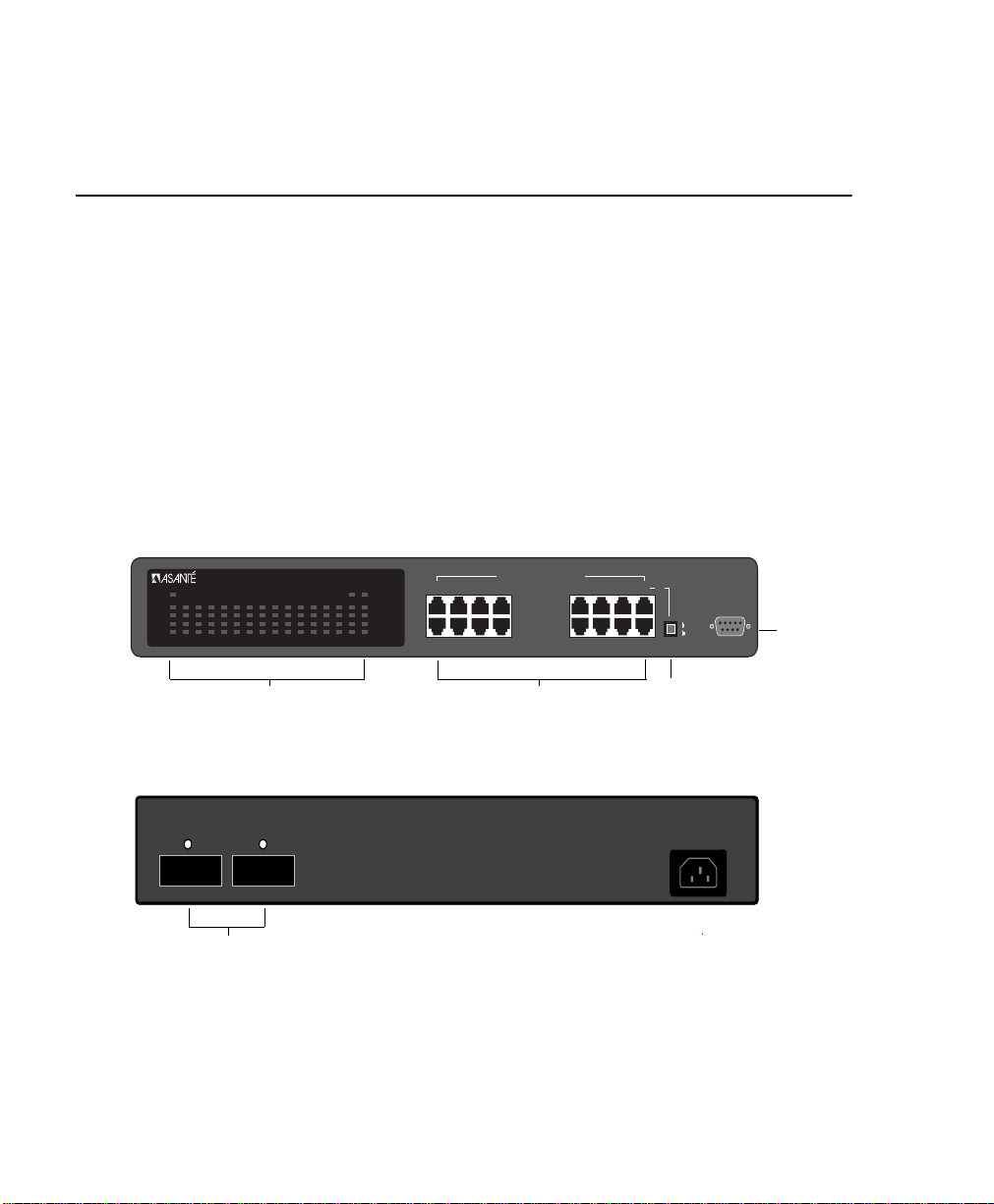
The IntraSwitch 6216M has 16 fixed 10/100 ports, which
includes two optional Asanté Media Independent Interface
(MII) expansion slots, and built-in Web-based network
management.
The two Asanté MII expansion slots allow for the addition of
100Base-FX or 10Base-FL connections.
IntraSwitch
6216M
MII2MII1
2468
1357
Figure 1-1 IntraSwitch 6216M Front Panel
Switched 10/100Mbps Ports
10 12 14 16
9111315
Sixteen 10/100Base-T Ports
or
Uplink
Switch
Uplink
Normal
Console
Console
Port
MII 2 (Port 16) MII 1 (Port 15)
Two Asanté Media Independent Interface
(MII) Expansion Slots
Page 1-2
100-240Vac Input
Figure 1-2 IntraSwitch 6216M Back Panel
Page 18
IntraSwitch 6224
IntraSwitch
Power
100Mbps
FDP
Data
Link
2345678910111213141516
1
>1 3 5 10 25 50 75 90<
6224
Utilization
LEDs
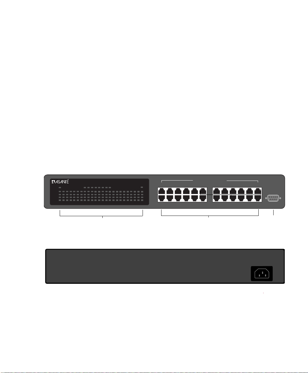
The IntraSwitch 6224 is a high performance 24-port 10/100
Ethernet switch. The IntraSwitch 6224 is designed for heavy
duty desktop users, and features a backplane that is capable of
supporting up to four Gbps of traffic. The 6224 can sustain fullduplex, full wire speed (148,800 packets per second per port)
non-blocking throughput. The IntraSwitch 6224 also supports
easy load monitoring via the front panel Led Utilization
indicators. Only the IntraSwitch 6216M model supports the
pushbutton Uplink selector, which eliminates the need for a
crossover cable, and only the 6216M supports optional internal
Asanté Fiber MII modules, which enable long distance
connections. Otherwise, the IntraSwitch 6224 and 6216M have
identical SNMP and RMON management features including the
built-in Web Management Server.
.
IntraSwitch
17 18 19 20 21 22 23
6224
24681012
24
1357
Switched 10/100Mbps Ports
911
14 16 18 20 22 24
13 15 17 19 21 23
2410/100Base-T Ports
LEDs
Console
Console
Port
Figure 1-3 IntraSwitch 6224 Front Panel
Figure 1-4 IntraSwitch 6224 Back Panel
100-240Vac Input
Page 1-3
Page 19

Introduction
IntraSwitch
Components
MII Expansion Slots
The IntraSwitch 6216M has two Media Independent Interface
(MII) expansion slots on the back panel. The expansion slots
provide connections for the addition of various media access
modules, including: 100Base-FX or 10Base-FL. See “Installing
MII Expansion Modules” in Chapter 2 for more information.
Console Port
The Console Port is a DB-9 serial port which may be used for
console operations on the IntraSwitch 6216M and 6224. When
configured, it can be used for Switch management and for serial
download. See “Out-of-Band Management” in Chapter 4 for
more information.
10/100 Ports
The sixteen 10/100 ports on the IntraSwitch 6216M (twentyfour on the IntraSwitch 6224) provide connections f or 10Base-T
or 100Base-TX (Fast Ethernet) network devices. See
“Connecting to the Network” in Chapter 2 for more
information.
LEDs
The LEDs on the IntraSwitch 6216M and 6224 indicate the AC
power and status of each 10/100 port. The LEDs also indicate
installation of IntraSwitch 6216M Asanté MII expansion
modules, if installed. See “LED Indicators” in Chapter 3 for more
information. The IntraSwitch 6224 also provides a convenient
LED Utilization indicator for monitoring total backplane traffic
volume.
Page 1-4
Power Supply Connector
The power supply connector provides the unit’s 100-240VAC
power connection.
Page 20

Configuration/ Management
Configuration/
Management
The IntraSwitch can be managed by any of the following
methods:
❏ Out-of-band (via the console port)
❏ In-band T elnet
❏ HTTP server (Web browser management)
❏ SNMP-compatible network manager
Console/Telnet Management
Through Console and Telnet operation, the IntraSwitch can be
configured and managed manually using the Configuration
Menu option. In addition to “Configuration,” options are
provided for “General Information” and “Statistics.” See Chapter
5 “Console Management” for more information.
Web Browser Management
The IntraSwitch has a built-in HTTP (Hypertext Transfer
Protocol) server which facilitates management with any World
Wide W eb browser .
Refer to Chapter 8 for information on using a Web browser to
manage the IntraSwitch.
SNMP-Based Management
The SNMP (Simple Network Management Protocol) may be
used to manage the IntraSwitch and any installed expansion
module. Any SNMP-based network management application
such as Web-based management software can be used. Refer to
Chapter 4 and to Chapter 8 for more information.
Switching
Capacity
Each 10Base-T/100Base-TX port can forward Ethernet
minimum-sized 64-byte packets at the maximum attainable rate
of 14,880 or 148,000 packets per second (pps).
The IntraSwitch fully supports the 802.1d transparent Ethernet
bridging standard. IEEE 802.1d compliance provides automatic
address learning, packet filtering, protection against corrupted
frames and fragments, and the Spanning Tree Protocol.
Page 1-5
Page 21

Introduction
Intelligent
Forwarding
The Asanté switc hing engine supports automatic fragment fr ee
packet forwarding. Fragment free switch mode allows the
switch to make the fastest possible s witching decisions without
forwarding runt packages on the network. The switch
automatically drops (or filters) illegally short packets known as
runts, which prevent bad packets from propagating across
segments. Runts are usually the result of packet collisions on a
congested network.
The Asanté switching engine also supports store and forward
switching. It will automatically choose the safest and fastest
method of switching if the source and destination are at the
same speed. If the speeds are different, such as for a 10Mbps
workstation connected to a 100Mbps server, the switch will
buffer and read the entire packet, perform a data validity check,
then forward the packet at the new speed. With Asanté
Intelligent Forwarding your FriendlyNet Switch will
automatically pick the best and fastest switching method for
you.
∆ Note: Intelligent Forwarding is an automatic fea-
ture of the IntraSwitch and cannot be altered by
the user.
Chassis Design The IntraSwitch chassis is rack-mountable and is 1.5 RU (rack
units) high.
Page 1-6
▲ Important! Do not remove the IntraSwitch’s
cover. This will invalidate the Asanté Limited
Lifetime Warranty. Refer service to qualified service personnel.
Page 22

Features The IntraSwitch has the following features:
❏ 16 (IntraSwitch 6216M) or 24 (IntraSwitch 6224)
fixed, 10/100 switched ports with RJ-45 connectors.
❏ Two optional Asanté MII expansion slots (IntraSwitch
6216M only), which replace ports 15 and 16. The
slots accommodate 100Base-FX, and 10Base-FL modules.
∆ Note: Using the Asanté MII Module will disable
the respective front panel 10/100 ports 15 or 16.
❏ HTTP server whic h pro vides J av a-enabled fr ont panel
view and SNMP management and configuration via
any supported W orld Wide W eb browser
❏ Telnet (in-band) and Console (out-of-band) manage-
ment
❏ Support for 8,192 MAC addresses per unit
❏ Full duplex support on all ports
❏ NWay auto-negotiation on 10/100 ports
❏ Full 100Mbps wire-speed, non-blocking packet trans-
fers for total throughput of 1Gbps per unit
(IntraSwitch 6216M) or 4Gbps per unit (IntraSwitch
6224)
❏ BootP and TFTP support
❏ RMON support (1 group)
❏ MIB II, Bridge MIB support
❏ Private MIB support (provides IP-to-port mapping)
❏ 802.1d Spanning Tree support
Features
Package
Contents
The IntraSwitch is shipped with the following items:
❏ (1) IntraSwitch Ethernet switch
❏ (1) power cord
Page 1-7
Page 23

Introduction
❏ (2) rack-mounting brackets
❏ (16) standard Phillips screws
❏ (1) MII cover bracket (IntraSwitch 6216M)
❏ (4) Self-adhesive rubber feet)
❏ (1) User’s Manual (this book)
❏ (1) Registration Card
❏ (1) Quick Install Card
▲ Important! If you are missing any of the items
listed above, contact the dealer from whom you
purchased the unit.
Tools and
Materials
Some tools and materials that are not supplied with the
IntraSwitch are needed to connect it to an Ethernet network.
The table below lists the tools and materials required for
connecting devices to the IntraSwitch’s ports and for rackmounting the unit.
∆ Note: For specific instructions on connecting
network devices to the IntraSwitch, see “Connecting to the Network” on page 2-6.
Table 1-1 Tools and Materials Required
Action Tool/Material Required
Connecting 10/100
ports
Connecting 100BaseFX port (optional MII
module)
Standard Category 5 UTP straight-through
cable with RJ-45 connectors.
Standard Category 5 UTP cross-over cables
with RJ-45 connectors.
Dual 62.5/125 micron graded-index
multimode fiber-optic cable fitted with SC
connectors.
Page 1-8
Page 24
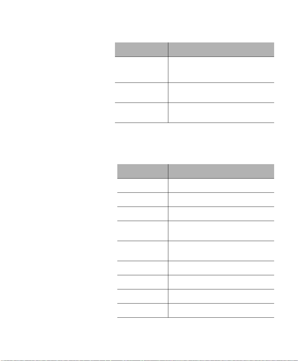
Action Tool/Material Required
Factory Defaults
Factory
Defaults
Connecting 10BaseFL port (optional MII
modules)
Connecting to the
Console port
Rack-mounting the
IntraSwitch
Dual 62.5/125 micron graded-index
multimode fiber optic cable fitted with ST
connectors.
Straight-through RS-232 cable with a 9-pin
male D-subminiature connector.
Phillips screwdriver for mounting the two
rack brackets on the unit.
The IntraSwitch is shipped with the following factory default
settings:
Table 1-2 Factory Default Settings
Configuration Default Setting
IP address 0.0.0.0
Subnet Mask 0.0.0.0
Default Gateway 0.0.0.0
Switching Mode
Intelligent Forwarding (Automatic Fragment
Free/Store and Forward)
10/100 Ports Auto-negotiation enabled; auto-negotiates to
10Mbps or 100Mbps, half duplex
Spanning Tree Enabled
BC Storm Threshold 7000 packets per second
Console Baud Rate 9600 Baud
Password Asante
Page 1-9
Page 25

Factory Defaults
Page 1-10
Page 26

2
Installation
This chapter explains how to install, connect, and configure
the IntraSwitch 6216M and 6224 to work with y our networ k. It
also explains how to install an MII expansion module in the
IntraSwitch 6216M.
This chapter contains the following sections:
❏ Installation Guidelines
❏ Installation Overview
❏ Rack Mounting/Desktop Placement
❏ Installing Asanté MII Modules (IntraSwitch
6216M Only)
❏ Connecting Power
❏ IntraSwitch Power Sequence
❏ Connecting to the Network
❏ Configuring for Management
Page 27

Installation
Installing the IntraSwitch
Installation
Guidelines
Power Requirements
The source electrical outlet should be installed near the
IntraSwitch, be easily accessible, and be properly grounded.
Make sure the power source adheres to the following
guidelines:
❏ Voltage range: 100 to 240 VAC
❏ Frequency range: 60/50 Hz
❏ Maximum current range: 2 A
Environmental Requirements
The IntraSwitch must be installed in a clean, dry, dust-free area
with adequate air circulation to maintain the following
environmental limits:
❏ Temperature: 0° to 40° C
❏ Relative Humidity: 5% to 85% non-condensing
Avoid direct sunlight, heat sources, or areas with high levels of
electromagnetic interference.
Cooling and Airflow
Do not restrict air flow by covering or obstructing air vents on
the sides of the chassis.
Page 2-2
Installation
Overview
The table below describes the steps needed to install the
IntraSwitch. The steps that are optional are labeled “optional”
and the steps that are required are labeled “required.” The
sections that follow explain each step in detail.
Page 28
Rack Mounting/Desktop Placement
Table 2-1 Installation Overview
Step Action
Rack Mounting/
Desktop
Placement
Equipment Rack
Installation
1 (required) Open the box and check the contents.
See “Package Contents” on page 1-7 for a complete
list of the items included with your IntraSwitch.
2 (optional) Install MII expansion module(s), if any.
See “Installing MII Modules” on page 2-5.
3 (required) Install the IntraSwitch in an equipment rack or prepare
it for desktop placement.
See “Rack Mounting/Desktop Placement” on page 2-3.
4 (required) Connect the power supply.
See “Connecting Power” on page 2-6.
5 (required) Connect network devices to the IntraSwitch.
See “Connecting to the Network” on page 2-6.
6 (optional) Configure the IntraSwitch for management
capabilities.
See “Configuring for Management” on page 2-8.
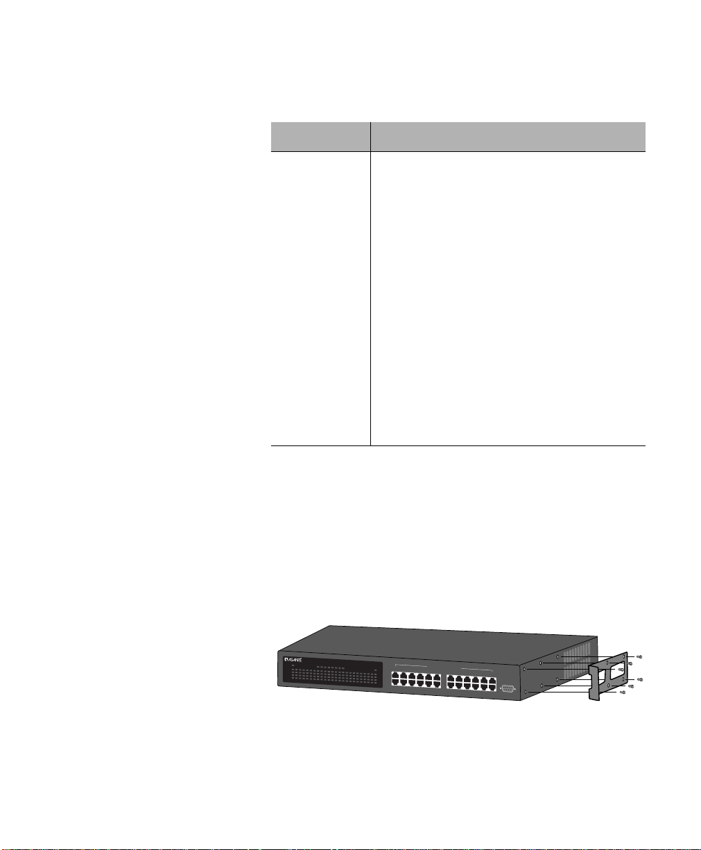
The IntraSwitch can be installed in a standard 19-inch
equipment rack. It can also be placed on a stable horizontal
surface with support capabilities of 12 pounds (5.4 kilograms).
To install the unit in an equipment rack, use the following
procedure. Refer to Figure 2-1 below.
Power
100Mbps
FDP
Data
Link
1
2345678910111213141516
Utilization
>1 3 5 10 25 50 75 90<
IntraSwitch
17 18 19 20 21 22 23
6224
24
Switched 10/100Mbps Ports
24681012
1357
911
14 16 18 20 22 24
13 15 17 19 21 23
Figure 2-1 IntraSwitch Rack Installation
Console
Page 2-3
Page 29

Installation
▲ Important! Disconnect all cables from the
IntraSwitch before continuing.
∆ Note: You can install the IntraSwitch in an
equipment rack before installing an expansion
module.
Place the IntraSwitch on a flat, stable surface.
1
Locate a rack-mounting bracket (supplied) and
2
place it over the mounting holes on one side of
the unit.
Insert six screws (supplied) into the holes and
3
tighten with a Phillips screwdriver.
Repeat the two previous steps for the unit’s
4
other side.
Place the unit in the equipment rack.
5
Secure the unit by screwing its mounting brack-
6
ets to the equipment rack.
Free-Standing/
Page 2-4
Desktop
Installation
▲ Important! Make sure the unit is supported
until all the mounting screws for each bracket
are secured to the equipment rack. Failure to do
so could cause the unit to fall, resulting in personal injury or damage to the unit, or both.
If you are installing an MII module at this time,
proceed to “Installing MII Modules” on page 2-5.
If you are not installing an MII module at this
time, proceed to “Connecting Power” on
page 2-6.
The IntraSwitch has four rubber feet on the bottom of the
chassis that allow for free-standing installation of the unit.
For free-standing/desktop placement:
Page 30

Installing Asanté MII Modules (IntraSwitch 6216M Only)
Attach the four rubber pads (supplied) to the
1
bottom of each corner of the IntraSwitch.
Place the unit on a flat surface with a minimum
2
area of 17.1” x 13.5” (434.3 mm x 342.9 mm)
and support capacity of 12 lbs (5 kg).
Make sure there is enough ventilation space
between the IntraSwitch and surrounding
objects.
Installing
Asanté MII
Modules
(IntraSwitch
6216M Only)
The IntraSwitch 6216M has two optional Media Independent
Interface (MII) expansion slots on the rear panel whic h provide
for connection to various types of media access modules,
including:
❏ Asanté 100Base-FX
❏ Asanté 10Base-FL
The MII expansion modules comply with IEEE 802.3 and
802.3u specifications and are sold separately. To install an MII
expansion module:
▲ Important! The MII expansion modules are
hot-swappable; you can install or remove a module without turning off power.
Align the bottom of the MII module with the rails
1
on the inside of the MII 1 or MII 2 slot. Slide the
module into the expansion slot until it stops, then
push the module in gently until it seats with the
connector.
Observe the MII 1 and MII 2 LED indicators on
2
the front panel. The LEDs will indicate proper
insertion of the modules.
∆ Note: When MII 1 and/or MII 2 modules are
installed, port 15 (MII 1) or port 16 (MII 2) will
be disabled.
Page 2-5
Page 31

Installation
Connecting
Power
Connecting to
the Network
To connect power to the IntraSwitch:
▲ Important! Carefully review the power
requirements on page 2-2 before connecting
power to the IntraSwitch.
Plug one end of the supplied power cord into
1
the power connector on the back of the unit.
Plug the other end into a grounded AC outlet.
2
The front panel LEDs blink and the Power LED
3
illuminates.
▲ Important! If the power does not come
on, refer to Appendix A, “Troubleshooting.”
The unit is ready for connection to the networ k.
The IntraSwitch unit may be connected to an Ethernet
network, with the unit powered either on or off.
Connect network devices to the IntraSwitch, fol-
1
lowing the cable guidelines outlined below.
After the unit is connected to the network, it
2
can be configured for management capabilities.
See “Configuring for Management” on page 2-8.
10/100 Ports
Cabling Procedures
Page 2-6
The 16 fixed 10/100 ports allow for the connection of 10Base-T
or 100Base-TX network devices. The ports are compatible with
IEEE 802.3 and 802.3u standards.
▲ Important! The IntraSwitch must be located
within 100 meters of its attached 10Base-T or
100Base-TX devices.
Page 32

Connecting to the Network
Table 2-2 10/100 Ports Cable Guidelines
Connecting To Cable Required
MII Expansion Ports Cabling Procedures
100Base-FX
Module
10Base-FL
Module
Network Station Category 5 UTP (Unshielded Twisted-Pair) straight-
Repeater/Hub Category 5, UTP cross-over cable (100 meters
Repeater/Hub’s
Uplink port
through cable (100 meters maximum) with RJ-45
connectors.
maximum) with RJ-45 connectors.
Category 5, UTP straight-through cable (100 meters
maximum) with RJ-45 connectors.
The optional Asanté MII expansion slots on the rear panel allow
for the connection of Asanté fibre optic 100Base-FX, or 10BaseFL media modules.
Table 2-3 100Base-FX MII Module Cable Guidelines
Connecting To Cable Required
All Network
Devices
Table 2-4 10Base-FL MII Module Cable Guidelines
Connecting To Cable Required
ST Connector
All Network
Devices
Dual 62.5/125 micron graded-index multimode fiberoptic cable with an SC connector.
Dual 62.5/125 micron graded-index multimode fiberoptic cable with a dual ST connector.
Cabling Scenarios The following diagram illustrates some cabling scenarios
available with the IntraSwitch units. Note that the rear panel
MII connections do not apply to the IntraSwitch 6224
Page 2-7
Page 33

Installation
Col
15678
Pwr
Power
100Mbps
FDP
Data
Link
12345678910111213141516
straight-through cable
(100m max. length)
Partition
Col
91011
4
3
15678
2
12
Pwr
Link/Receive
3
4
2
1
7
8
6
3
2
Partition
4
Link/Receive
91011
5
12
100BASE-TX Ports
Repeater/Hub — UPLINK Port
MII 1 MII 2
2468
1357
cross-over cable
(100m max. length)
3
4
2
1
6
5
100BASE-TX Ports
7
8
AsantéFAST 100 Hub
11
12
10
9
straight-through cable
(100m max. length)
MII connection
11
12
10
9
must be fibre
AsantéFAST 100 Hub
(2km max length)
from MII port
on rear panel
Switched 10/100Mbps Ports
10 12 14 16
9111315
straight-through cable
(100m max. length)
from port 16 (Uplink)
or
Console
Uplink
Normal
Uplink
Partition
Col
91011
4
3
15678
2
Pwr
Link/Receive
Repeater/Hub — STANDARD Port
Col
15678
Pwr
Repeater/Hub — UPLINK Port
Repeater/Hub — Standard Port
100Base-TX
Server
Printer
Network
Station
straight-through cable
Figure 2-2 IntraSwitch Cabling Scenarios
∆ Note: Pressing the Uplink switch toggles the
usage of port 16 from normal to uplink or vice
versa. This uplink feature is available only for
regular RJ-45 port, and not for MII ports. When
port 16 is used for uplink, the connection
between port 16 to standard hub is straightthrough cable.
Port 16 in Uplink mode can
be connected to hub using
straight-through cable
(100m max. length)
3
4
2
1
7
8
6
5
12
100BASE-TX Ports
3
4
2
1
6
2
Partition
4
3
Link/Receive
5
91011
12
100BASE-TX Ports
(100m max. length)
10
9
AsantéFAST 100 Hub
7
8
11
12
9
AsantéFAST 100 Hub
11
12
10
Configuring for
Management
To use the IntraSwitch as a managed switch, it must be
configured with an IP address. This can be accomplished in one
of two ways:
❏ automatically using BootP (default)
❏ manually via the unit’s Console port
BootP Configuration The IntraSwitch is shipped with BootP support. BootP allows
the IntraSwitch to be automatically configured with an IP
Page 2-8
Page 34

Configuring for Management
address when it is connected to the network and is powered
on, if your network contains a BootP server configured with
available, valid IP addresses.
▲ Important! BootP configuration only works if
the IntraSwitch does not have an IP address
assigned to it.
Make sure your network has a BootP server con-
1
figured with a valid IP address entry for the
IntraSwitch.
When the IntraSwitch is connected to the net-
2
work and is powered on, it automatically transmits a BootP request across the network (up to
10 times) until it receives a valid IP address from
the BootP server.
After an IP address is received, the IntraSwitch
3
can be managed via in-band access. See Chapter
4 for more information.
To verify that a valid IP address was received, use a tool such as
Ping1 to try and access the IntraSwitch; if you can access the
IntraSwitch, it is properly configured with an IP address.
See “Bootstrap Configuration” in Chapter 5 for more
information on using BootP.
Console
Configuration
T o manuall y configure the Intr aSwitch with an IP addr ess via its
Console port, use a VT100 terminal or emulator (such as Hyper
Terminal, ProComm, or ZTerm) running on a workstation or
personal computer to connect to the switch’s Local Management Interface.
1. Ping is an application that can be used to test whether a remote device is
properly connected to a network.
Page 2-9
Page 35

Installation
Using a straight-through RS-232 cable with a 9-
1
pin male D-subminiature plug at one end, connect a terminal or workstation (PC or Macintosh)
running a terminal emulator to the Console port
on the front of the IntraSwitch.
Make sure both units are powered on.
2
If using a PC with a terminal emulator, make
sure it is configured with the following terminal
settings:
❏ Baud: 9600
❏ Data Bits: 8
❏ Parity: None
❏ Stop Bits: 1
❏ Flow Control: None
Once connected, the Local Management Main
3
Menu appears on the terminal screen, as shown
in Figure 2-3.
Page 2-10
Figure 2-3 Local Management Interface Main Menu
Type c to open the Configuration Menu.
4
The “Enter Password” prompt appears.
Type your password at the prompt.
5
▲ Important! The default password is
Asante. The password is case-sensitive.
Page 36

Configuring for Management
For information on changing the password,
see “Changing the Password” in Chapter 5.
Type i to open the Switch IP Configuration menu.
6
Type i to select the option “Set IP Address.”
7
Type the IP address to be assigned to the
8
IntraSwitch at the prompt.
∆ Note: Depending on your network configu-
ration, you may also need to set subnet mask
and default gateway (router) information.
See “System IP Configuration” in Chapter 5
for instructions.
Press Return.
9
10
The IntraSwitch is configured with an IP address and can now
be managed via in-band access. See Chapter 4, “Setting Up For
Management” for more information.
Type q to return to the Configuration Menu.
Page 2-11
Page 37

Installation
Page 2-12
Page 38

3
LED Indicators
This chapter describes the IntraSwitch 6216M and 6224’ s front
panel and explains how to interpret its port LEDs and other
function indicators.
This chapter contains the following sections:
❏ LED Indicators
❏ Port LEDs
❏ Function Indicator Lights
Page 39

LED Indicators
LED Indicators
IntraSwitch
6216M and 6224
LED Indicators
Power
100Mbps
FDP
Data
Link
21 3 4 9 10 11 125 6 7 8 13 14 15 16
IntraSwitch 6216M and 6224, Common LEDs
The IntraSwitch 6216M and 6224 front panels contain LEDs
which provide a visual indication for each 10/100TX port. The
LEDs may also be used to assist with troubleshooting. See
Figures 3-1 and 3-2. The four rows of port LEDs display:
❏ 100Mbps (100Mbps operation)
❏ FDP (full duplex operation)
❏ Data
❏ Link
Both IntraSwitch 6216M and 6224 contain an LED which
indicates AC power on when lit.
IntraSwitch 6216M LEDs
In addition to the LEDs in common with the IntraSwitch 6224
as described above, the IntraSwitch 6216M has MII 1 and MII 2
LEDs. These LEDs convey the presence of the MII expansion
modules (if installed).
IntraSwitch
6216M
MII2MII1
Page 3-2
Figure 3-1 IntraSwitch 6216M LED Panel
Page 40

IntraSwitch 6216M and 6224 Port LEDs
IntraSwitch 6224 LEDs
In addition to the LEDs in common with the IntraSwitch 6216M
as described above, the IntraSwitch 6224 has a row of eight
LEDs which display the percentage of Switch utilization.
Power
100Mbps
FDP
Data
Link
2345678910111213141516
1
IntraSwitch
6216M and 6224
Port LEDs
Utilization
IntraSwitch
>1 3 5 10 25 50 75 90<
17 18 19 20 21 22 23
6224
24
Figure 3-2 IntraSwitch 6224 LED Panel
The IntraSwitch 6216M and 6224 have four rows of LEDs. The
following table describes their color and function.
Table 3-1 IntraSwitch 6216M and 6224Port LED Descriptions
LED Color Meaning
100Mbps green The port speed is 100Mbps.
FDP amber The port is in full duplex mode.
Note:
Full duplex means that a port
can transmit and receive at the same
time.
Data green T raffic activity is occurring on the port,
transmit [TX] or receive [RX].
Link green The port is connected to a powered-
on node or other network device.
∆ Note: For information on using the LEDs to
troubleshoot problems with your networ k, see
Appendix A, “Troubleshooting.”
Page 3-3
Page 41

LED Indicators
IntraSwitch
6216M Function
LEDs
IntraSwitch
6224 Function
LEDs
The IntraSwitch 6216M has three function indicator lights,
which comprise one Power and two MII LED indicators. The
following table describes their color and function.
Table 3-2 IntraSwitch 6216M Indicator Light Description
LED Color Meaning
Power green The IntraSwitch is receiving AC
electrical power.
MII 1, MII 2 green Indicates the presence of an Asanté MII
Module in MII slot 1 (port 15) or MII slot
two (port 16). No connection or link is
required for the MII LED to be lit, just the
module installation.
The IntraSwitch 6224 has one Power indicator and a row of
eight Utilization indicators. The following table describes their
color and function.
Table 3-3 IntraSwitch 6224 Indicator Light Descriptions
LED Color Meaning
Power green The IntraSwitch is receiving AC
electrical power.
Page 3-4
Utilization
1, 3, 5, 10,
25, 50, 75,
90%
green Row of eight LEDs which Indicates the
percentage of utilization of the
IntraSwitch ports. The LEDs will light if
backplane traffic is less than or equal to
the indicated value. Total backplane
capacity is four Gbps. If utilization
indicates 25% or greater, the LED color
will be amber.
Page 42

4
Setting Up For
Management
This chapter describes the IntraSwitch 6216M and 6224’s
management options and explains how to connect to the unit
using those options.
This chapter contains the following sections:
❏ Overview
❏ Management Scenarios
❏ Out-of-Band Management
❏ In-Band Management
Page 43

Setting Up For Management
IntraSwitch Management
Overview The IntraSwitch 6216M and 6224 and any installed Asanté MII
Modules can be managed using any of the following methods:
Table 4-1 Management Options
Method Type Description
Console out-of-band
management
Telnet
(four sessions
maximum)
HTTP Server in-band
SNMP-Based
Network
Management
Software
in-band
management
management
in-band
management
local connection to the
IntraSwitch via the Console port
remote connection over the
network to the IntraSwitch via
Telnet session
remote connection to the
IntraSwitch via a Web browser
remote connection to the
IntraSwitch via any SNMP-based
network management application
This chapter describes how to connect to the IntraSwitch using
either out-of-band or in-band management, as illustrated in
Figure 4-1.
For information on each management method, see the following:
❏ Console or Telnet management — see Chapter
5, Console Management.
❏ HTTP Server management — see Web Browser
Management, Chapter 8
❏ SNMP-based network management software — see
SNMP-Based Management Software on page 4-6.
Page 4-2
Page 44

Out-of-Band Management
Management
Scenarios
The following diagram illustrates the management options
available with the IntraSwitch 6216M and 6224.
IntraSwitch 6216M
Power
100Mbps
FDP
Data
Link
12345678910111213141516
IntraStack 6014DSB
Workstation
MII1 MII2
2468
1357
Switched 10/100Mbps Ports
In-Band Management:
• Telnet connection to the IntraSwitch's Local Management Interface
• Connect to the IntraSwitch's HTTP server via a Web browser
• Connect to the IntraSwitch via any SNMP-based network
management software application such as IntraSpection
Figure 4-1 IntraSwitch 6216M and 6224 Management Options
Out-of-Band
Management
Out-of-band network management allows you to configure,
manage, and monitor the IntraSwitch and any installed
expansion modules. You can perform these functions via the
following method:
❏ By attaching a terminal (or a terminal emulator)
to the IntraSwitch’s Console port and using the
menu-driven Local Management Interface.
or
10 12 14 16
9111315
Console
Uplink
Normal
Uplink
Stand-alone Terminal or PC
Out-of-Band Management:
• Direct connection to the IntraSwitch's Local
Management Interface via the Console port
Out-of-band network management is guaranteed ev en when the
in-band Ethernet network is down.
To access the IntraSwitch Local Management Interface using
out-of-band management:
Connect a stand-alone terminal or a PC running
1
a terminal emulator directly to the IntraSwitch’s
Console port using a straight-through RS-232
serial cable with a male connector.
Page 4-3
Page 45

Setting Up For Management
Make sure both units are powered on.
2
If using a PC or Mac with a terminal emulator to
connect to the Console port, make sure it is configured with the following terminal settings:
❏ Baud rate: 9600
❏ Data Bits: 8
❏ Parity: None
❏ Stop Bits: 1
❏ Flow Control: None
Once connected, the Local Management Inter-
3
face Main Menu appears on the screen, as
shown in Figure 4-2.
Page 4-4
Figure 4-2 Local Management Interface Main Menu
See Chapter 5, “Console Management,” for information on using the Local Management Interface to manage the IntraSwitch and an y installed
expansion modules.
▲ Important! A password is needed to access
the Configuration Menu. The default password
is Asante. The password is case-sensitive.
Page 46

In-Band Management
In-Band
Management
In-band network management allows you to manage, control,
and monitor the IntraSwitch and any installed expansion
modules over the Ethernet network.
You can perform these functions by accessing the IntraSwitch
via any of the following methods:
❏ By connecting with a Telnet program and using
the Local Management Interface.
❏ By connecting with any common World Wide
Web browser, and using the Web Management
Interface.
❏ By connecting with any SNMP-based network
management application and using its interface.
To manage the IntraSwitch via in-band management:
Make sure the network to which the IntraSwitc h
1
is connected is functioning.
Make sure the IntraSwitch is configured with
2
valid IP information.
See “Configuring for Management” on page 2-8.
Connect to the IntraSwitch via Telnet, with a
3
Web browser, or with any SNMP-based network
management application.
Telnet
See Chapter 5, Console Management, for information on managing the IntraSwitch.
∆ Note: Almost all management screens using
a Telnet are identical to those of the out-ofband Console interface.
Web Browser
Refer to Chapter 8, Web Browser Management
Manual, for information on managing the
IntraSwitch with a Web browser.
Page 4-5
Page 47

Setting Up For Management
SNMP-Based Management Software
Refer to your SNMP Software Manual for information on managing the IntraSwitch with SNMPbased management software.
The Asanté private MIB for the IntraSwitch is
available from the Asanté ftp site, ftp.asante.com.
Page 4-6
Page 48

5
Console
Management
This chapter describes how to manage the IntraSwitch 6216M
and 6224 using the out-of-band Console or in-band Telnet
interface.
This chapter contains the following sections:
❏ Overview
❏ Configuration Tasks
❏ Management Tasks
❏ Local Management Interface
❏ General Information Menu
❏ Configuration Menu
❏ Logging into the Configuration
Menu
❏ Statistics Menu
Page 49

Console Management
Console Management
Overview The IntraSwitch 6216M and 6224’ s Local Management Interf ace
is a menu-driven application which provides management and
configuration support for the unit and each of its ports.
The Local Management Interface can be accessed via two
methods:
❏ Out-of-band connection to the Console port.
❏ In-band connection via Telnet (four sessions
maximum).
This section describes each menu within the Local
Management Interface as well as how to perform the
configuration/management tasks outlined in Tables 5-1 and 5-2.
Table 5-1 Configuration Tasks
Configuration Task Page
Page 5-2
Logging into the Configuration Menu
System Administration Information
Changing System IP Information
Changing the Boot Bank Number page 5-15
Executing Software Locally page 5-15
Loading Software Remotely
Changing Community Strings
Configuring Duplex Mode page 5-24
Configuring Auto-Negotiation page 5-25
page 5-6
page 5-10
page 5-12
page 5-16
page 5-18
Page 50

Management Tasks
Management
Tasks
Table 5-2 Management Tasks
Management Task Page
Enabling Traps
Adding a Trap Receiver
Deleting a Trap Receiver
Enabling or Disabling a Port
Performing a Software Upgrade at Runtime page 5-35
Displaying the MAC Address Table page 5-29
Searching the MAC Address Table
Setting the MAC Address Age-Out Time page 5-31
Enabling the Duplicated-IP Trap page 5-32
Viewing the Trap Log page 5-32
Resetting the IntraSwitch page 5-41
Scheduling a Reset page 5-41
Viewing the System Log page 5-42
page 5-19
page 5-19
page 5-20
page 5-23
page 5-30
Clearing the System Log page 5-43
Setting the Console and Telnet Idle Time-out Period page 5-44
Changing the Password page 5-46
∆ Note: For information on monitoring statistics,
viewing the IntraSwitch’s current operating and
system information, see Chapter 6, “Status Monitoring, Traffic, and Statistics.”
Page 5-3
Page 51

Console Management
Local
Management
Interface
After you connect to the Local Management Interface using
either out-of-band Console or in-band Telnet connection as
described in Chapter 4, the Main Menu appears as shown in
Figure 5-1.
Main Menu
Figure 5-1 Local Management Interface Main Menu
From the Main Menu, you can access three submenus:
❏ General Information — page 5-5
❏ Configuration — page 5-6
❏ Statistics — page 5-50
If you are using T elnet, a fourth option will be available — Close
Connection. This option closes your remote connection to the
IntraSwitch’s Local Management Interface.
Page 5-4
Accessing a
Submenu
Exiting a
Submenu
To access a submenu, type the command letter of the
corresponding option (e.g., type g for General Information).
To exit a submenu, type q. To exit a command line (e.g., the
“Set Password” option in the Configuration Menu), press ctrl-c.
Page 52

General Information Menu
General
Information
Menu
The General Information Menu displays the IntraSwitch’s
current operating information; such as its name, IP address, and
boot information.
∆ Note: The information displayed on this screen is
read-only.
Accessing the General Information Menu
❏ Type g from the Local Management Interface Main
Menu. A screen similar to Figure 5-2 appears:
Figure 5-2 General Information Menu
▲ Important! For a description of each parame-
ter on the General Information Menu, see “General Information Menu Parameters” on page 6-3.
To exit the General Information Menu, press any key on your
keyboard.
Page 5-5
Page 53

Console Management
Configuration
Menu
The Configuration Menu allows you to manage and configure
the IntraSwitch and each of its ports.
Logging into the Configuration Menu
Type c from the Local Management Interface
1
Main Menu.
Enter your password at the “Enter Password”
2
prompt, then press Return.
▲ Important: The default password when
you first access the Configuration Menu is
Asante. The password is case-sensitive;
enter it exactly as shown.
For information on changing passw ords, see
“Changing the Password” on page 5-46.
The Configuration Menu appears, as shown in
Figure 5-3.
Page 5-6
Figure 5-3 Configuration Menu
From this menu you can access configuration sub-
3
menus by typing the command letter of the corresponding menu option (e.g., type a for the System
Administration Configuration Menu).
Page 54

Logging into the Configuration Menu
Configuration Menu Options
T able 5-3 provides an overview of each Configuration Menu
item.
Table 5-3 Configuration Menu Options
Menu Item Description
System Administration
Configuration
Switch IP Configuration
Bootstrap Configuration Allows you to change the boot method the
SNMP Configuration
Port Configuration
Spanning Tree Configuration
Displays and allows you to change the name,
location, and contact information for the
IntraSwitch.
See “System Administration Configuration” on
page 5-9.
Displays and allows you to change the
information needed to access the IntraSwitch
over the network (in-band management).
See “System IP Configuration” on page 5-10.
IntraSwitch uses for loading its software. Also
allows you to change the parameters used for
downloading a new version of runtime
software for the IntraSwitch.
See “Bootstrap Configuration” on page 5-12.
Displays and allows you to change the
IntraSwitch’s SNMP (Simple Network
Management Protocol) parameters; such as,
read/write community strings, trap
authentication, and trap receivers.
See “SNMP Configuration” on page 5-17.
Allows you to manually configure each of the
IntraSwitch’s ports for speed, connection, link
mode, and auto-negotiation. Also displays an
overall status of the IntraSwitch system.
See “Port Configuration” on page 5-20.
Displays and allows you to change the
IntraSwitch’s Spanning Tree parameters.
See “Spanning Tree Configuration” on page
5-27.
Forwarding DB/Security
Configuration
Allows you to view and search for addresses in
the IntraSwitch’s MAC Forwarding Table. Also
allows you to set a trap for duplicate IP
addresses and view the trap log.
See “Forwarding Database/Security
Configuration” on page 5-27.
Page 5-7
Page 55

Console Management
Menu Item Description
TFTP Image File
Downloading Configuration
System Reset Options Allows you to reset the IntraSwitch by
System Log
Set Idle Time-out
Change Password
Global Port Configuration
Return to Previous Menu
Allows you to upgrade the IntraSwitch’s
software.
See “TFTP Image File Downloading
Configuration” on page 5-33.
performing a “warm” reboot. Also allows you
to set the IntraSwitch for an automatic reset
(up to 24 hours) in advance.
See “System Reset Options” on page 5-39.
Allows you to view the IntraSwitch’s System
Log.
See “System Log” on page 5-42.
Allows you to set the idle time-out period when
using Console and Telnet to access the
IntraSwitch.
See “Idle Time-out” on page 5-44.
Allows you to change the password needed to
access the Configuration Menu.
See “Changing the Password” on page 5-46.
Allows you to change the configuration of all
ports simultaneously.
Exits the Configuration Menu and returns to
the Local Management Interface Main Menu.
Page 5-8
Page 56

Current Settings
Configuration Menu
System Administration Configuration
This menu displays and allows you to change the IntraSwitch’s
name, location, and contact information.
To access the System Administration Configuration Menu, type
a in the Configuration Menu. A screen similar to Figure 5-4
appears.
Figure 5-4 System Administration Configuration Menu
Current Settings
Table 5-4 explains each setting on the System
Administration Configuration Menu.
For information on using the menu, see:
❏ “Changing System Administration Informa-
tion” — page 5-10.
Table 5-4 System Administration Configuration Menu Settings
Menu Item Description
Switch Name
Switch Location
Switch Contact
The name of the IntraSwitch (up to 64 characters,
including spaces).
The location where the IntraSwitch is physically located
(up to 64 characters, including spaces).
The name of the person or entity responsible for the
IntraSwitch (up to 64 characters, including spaces).
Page 5-9
Page 57

Console Management
Changing System Administration Information
To change the IntraSwitch’s name, location, or contact
information:
Open the System Administration Configura-
1
tion Menu by typing a in the Configuration
Menu.
Type the command letter of the item to be
2
changed in the System Administration Configuration Menu.
Type the information at the prompt.
3
See Table 5-4 for a description of each parameter.
∆ Note: Each parameter is limited to 64 char-
acters, including spaces.
To cancel a selected option, press ctrl-c at
the command prompt.
Press Return.
4
The IntraSwitch’s system administration
information is changed.
To quit and return to the Configuration
Menu, type q.
Page 5-10
System IP Configuration
This menu displays and allows you to change the information
needed to access the IntraSwitch over the network via in-band
management.
To access the System IP Configuration Menu, type i in the
Configuration Menu. A screen similar to Figure 5-5 appears.
Page 58

Current Settings
System IP Configuration
.
Figure 5-5 System IP Configuration Menu
▲ Important: By default, each address is set
to 0.0.0.0.
Current Settings
Table 5-5 explains each setting on the System IP
Configuration Menu.
For information on using the menu, see “Changing System
IP Information” on page 5-12.
Table 5-5 System IP Configuration Menu Settings
Setting Description
Switch IP Address
Switch Subnet
Mask
Switch Default
Router
The IntraSwitch’s IP (Internet Protocol) address.
The IntraSwitch’s subnet mask.
The address of the IntraSwitch’s default router.
Page 5-11
Page 59

Console Management
Changing System IP Information
To change the IntraSwitch’s IP address, subnet mask, or
default router information:
Open the System IP Configuration Menu by
1
typing i in the Configuration Menu.
Type the command letter of the option you
2
want to change.
Type the new address at the prompt.
3
See Table 5-5 for a description of each
address.
▲ Important! Follow the format: num-
ber.number. number. number.
To cancel, press ctrl-c at the command
prompt.
Press Return.
4
The IntraSwitch’s IP information is changed.
To quit and return to the Configuration
Menu, type q.
Page 5-12
Bootstrap Configuration
This menu displays (and allows you to change) the bootstrap
parameters used for loading the IntraSwitch’s software at
startup, and for downloading a new version of software when
one is issued.To access the Bootstrap Configuration Menu, type
b in the Configuration Menu. A screen similar to Figure 5-6
appears.
Page 60

Current Settings
Bootstrap Configuration
Figure 5-6 BootStrap Configuration Menu
▲ Important! The IntraSwitch’s default Load
Mode setting is Local.
When the IntraSwitch is powered on, it loads its software via
one of two methods: locally (via its internal flash memory
which is the default setting) or remotely over the network.
Image Banks
The IntraSwitch has two banks to store its run time software.
The banks are referred to as bank 1 and bank 2.
Either of these banks may be the Boot Bank, which is the bank
where the runtime code will be loaded the next time the
IntraSwitch is booted.
When downloading new runtime image codes, the user may
specify either of the two banks as the Destination Bank in
which the new code will be loaded.
Page 5-13
Page 61

Console Management
Current Settings
Table 5-6 explains each setting on the Bootstrap
Configuration Menu.
For information on using the menu, see:
❏ “Loading Software Locally” — page 5-15
❏ “Loading Software Remotely” — page 5-16
▲ Important! For information on perform-
ing a software upgrade, see “Performing a
Software Upgrade” on page 5-35.
Table 5-6 Bootstrap Configuration Menu Settings
Setting Description
Running Image
Version/Date
Bank 1 Image
Version/Date
Bank 2 Image
Version/Date
Boot Server IP
Boot File Name
Boot Mode
The version and compilation date of runtime code that is
currently running on the IntraSwitch.
The version and compilation date of runtime code that is
stored in Bank 1.
The version and compilation date of runtime code that is
stored in Bank 2.
The IP address of the boot server providing BootP/TFTP
capabilities on your network.
The name of the IntraSwitch’s software file and its
network path.
The method for requesting the software image file from
the network.
BootP-TFTP — Sets the IntraSwitch to request an IP
address from a BootP server AND to download the
software’s image file through TFTP (Trivial File Transfer
Protocol).
▲ Important! To use this option, the IntraSwitch’s IP
address must be set to 0.0.0.0 and the Load Mode must
be set to Remote.
TFTP ONLY — Sets the IntraSwitch to only download the
software image file through TFTP.
▲ Important! To use this option, the IntraSwitch must
already have an assigned IP address and the Load Mode
must be set to Remote.
Page 5-14
Page 62

Setting Description
Bootstrap Configuration
Load Mode
Boot Bank
The current method for loading the IntraSwitch’s
software.
Local — Executes the software image file from the
IntraSwitch’s internal flash memory (default setting; the
IntraSwitch automatically reverts to this setting after
downloading a new software file).
Remote — Loads the software image file from a server
on the network.
▲ Important! To use the remote option, you must
select BootP-TFTP or TFTP as the Boot Mode.
The number of the image bank being used to load the
IntraSwitch’s software.
Note: The image bank is where the runtime code is
stored; the IntraSwitch has two image banks: Boot Bank
and Destination Bank.
Selecting the Boot Bank Number
T o select the Boot Bank that the Intr aSwitc h will boot from
the next time it boots up:
Open the Bootstrap Configuration Menu by
1
typing b in the Configuration Menu.
Type a in the Bootstrap Configuration Menu
2
to toggle the Boot Bank from 1 to 2 (or vice
versa).
Loading Software Locally
The IntraSwitch will always boot locall y unless the user sets
it to boot load remotely. It would then download the new
image code and reset to load locally.
Make sure the IntraSwitch is configured with
1
a valid IP address.
Open the Bootstrap Configuration Menu by
2
typing b in the Configuration Menu.
Type l in the Bootstrap Configuration Menu
3
to set the Load Mode to Local.
Page 5-15
Page 63

Console Management
The IntraSwitch is set to load software locally
from its flash memory. This occurs whenever
the unit is powered on or reset.
Loading Software Remotely
To set the IntraSwitch to (download its software) over the
network from a remote server:
Open the Bootstrap Configuration Menu by
1
typing b in the Configuration Menu.
Type s in the Bootstrap Configuration Menu,
2
select option Set Boot Server IP Address.
Type the IP address at the prompt of the
3
remote boot server which contains the unit’s
software image file, then press Return.
Type r to set the Load Mode to Remote.
4
Type f to select the option Set File Name.
5
Type the software’s file name and network
6
path at the prompt.
Page 5-16
Press Return.
7
The unit is set to download its software
remotely from the network. This will occur
the next time the unit is powered on or r eset.
Page 64

Current Settings
SNMP Configuration
SNMP Configuration
This menu displays the unit’s SNMP (Simple Network
Management Protocol) Configuration Menu.
This menu allows you to configure the unit’s read and write
community strings. It also allows you to specify which of your
network management stations will receive traps from the
IntraSwitch.
To access this, type n in the Configuration Menu. See Figure 5-7
.
Figure 5-7 SNMP Configuration Menu
Current Settings
Table 5-7 explains each setting on the SNMP Configuration
Menu.
For information on using the menu, see:
❏ “Changing Community Strings” — page 5-18
❏ “Enabling Traps” — page 5-19
❏ “Adding a Trap Receiver” — page 5-19
❏ “Deleting a Trap Receiver” — page 5-20
Page 5-17
Page 65

Console Management
Table 5-7 SNMP Configuration Menu Settings
Setting Description
SNMP Read
Community
SNMP Write
Community
Trap
Authentication
SNMP Trap
Receivers
The IntraSwitch’s SNMP read community string.
Note: The read community string is a single word that
defines access rights for reading SNMP data objects.
The default setting is public.
The IntraSwitch’s SNMP write community string.
Note: The write community string is a single word that
defines access rights for writing SNMP data objects.
The default setting is private.
The status of the SNMP agent to generate authentication
traps.
The default setting is disabled.
The IP addresses of the network management stations
that can receive traps from the IntraSwitch.
Normally, these addresses are the same as your network
management software systems’ IP address(es).
▲ Important! A maximum of four trap receivers is
allowed.
Changing Community Strings
To change the IntraSwitch’s community strings:
Open the SNMP Configuration Menu by typ-
1
ing n in the Configuration Menu.
Type r to change the read community string
2
or w to change the write community string.
Page 5-18
Type a new community string at the prompt.
3
See Table 5-7 for a description of read and
write community strings.
To cancel a selected option, press ctrl-c at
the command prompt.
Press Return.
4
To quit and return to the Configuration
Menu, type q.
Page 66

SNMP Configuration
Enabling Authentication Traps
The IntraSwitch can be set to generate authentication tr aps.
Authentication traps are messages sent across the network
to an SNMP network management station. They alert you
when someone without access rights attempts to change
the device’s MIB information.
To set the IntraSwitch to generate traps:
Open the SNMP Configuration Menu by typ-
1
ing n in the Configuration Menu.
Type t toggle trap authentication from dis-
2
abled to enabled.
To cancel, press ctrl-c at the command
prompt.
To quit and return to the Configuration
Menu, type q.
Adding a Trap Receiver
Trap receivers are the network management stations
designated to receive traps from the IntraSwitch when they
occur .
▲ Important! The maximum number of
trap receivers that can be set is four.
To add a trap receiver entry:
Open the SNMP Configuration Menu by typ-
1
ing n in the Configuration Menu.
Type a to Add a Trap Receiver.
2
Type the IP address of the network manage-
3
ment station you want to receive traps, then
press Return.
To cancel, press ctrl-c.
Type the trap receiver’s community string at
4
the prompt, then press Return.
Page 5-19
Page 67

Console Management
The trap receiver entry is added.
To return to the Configuration Menu, type q.
Deleting a Trap Receiver
To delete a trap receiver entry:
Open the SNMP Configuration Menu by typ-
1
ing n in the Configuration Menu.
Type d to Delete a Trap Receiver.
2
Type the number of the receiving network
3
management station entry to be deleted,
then press Return.
The trap receiver entry is deleted.
To return to the Configuration Menu, type q.
Port Configuration
This menu allows you to manually configure each of the
IntraSwitch’ s ports and any installed MII e xpansion modules f or
speed, connection, link mode, and auto-negotiation.
It also provides an overview of the entire IntraSwitch system’s
port operating status. The Advanced Port Configuration option
“v” allows you to configure ports BC filtering and its autonegotiation advertisement.
The default parameters for each of the IntraSwitch’s ports are:
❏ auto-negotiation — enabled; auto-negotiates to
10 or 100Mbps half or full duplex
Page 5-20
To access the Port Configuration Menu, type p in the
Configuration Menu. A screen similar to Figure 5-9 appears.
Page 68

Port Configuration
.
IntraSwitch
Current Port Settings
System
Information
Figure 5-8 Port Configuration Menu
Figure 5-9 Advanced Port Configuration Menu
Page 5-21
Page 69

Console Management
IntraSwitch System Information
Table 5-8 on page 5-22 explains the system information.
For directions on using this menu to view IntraSwitch
system information, see “Viewing IntraSwitch System
Information” on page 6-4.
Current Port Settings
The current port for which statistics are displayed is shown
at the top of the screen next to “Port Number:”.
Table 5-8 explains each setting on the Port Configuration
Menu.
For information on using the Port Configuration Menu, see:
❏ “Enabling/Disabling a Port” — page 5-23
❏ “Configuring Duplex Mode” — page 5-24
❏ “Configuring Auto Negotiation” — page 5-25
Table 5-8 Port Management Menu Settings
Setting Description
Page 5-22
Port Operating
Status
Port Number
BC Filter
The status of the IntraSwitch. This field displays symbols
for each of the unit’s 16 ports.
List of Port Symbols:
X — no port exists.
- (negative symbol) — a port exists but is not linked.
! — the port is disabled.
B — the port is in a blocking state.
S — the port is in a listening state.
R — the port is in a learning state.
+ — the port is in a forwarding state.
▲ Important! Type h “Help for Legends” in the Port
Management Menu for a list of the port symbols.
The port number for which parameters are shown.
The port’s capability to forward broadcast packets.
Enabled — broadcast packets will be discarded.
Disabled — broadcast packets will be processed
normally.
Page 70

Setting Description
Port Configuration
Port Status
Auto-Neg
Link Status
The administrative status of the port’s connection.
Enabled — port is enabled and can receive and forward
packets.
Disabled — port is disabled and cannot receive packets.
Note: If the port is disabled, it cannot not receive any
packets, even if the port’s Link Status is UP.
▲ Important! There is no indication on the front panel
that a port is disabled. The ports can only be seen in one
of the management modes. .
The status of the port’s auto-negotiation capability. This
field also shows the port’s speed and link mode
capability by using a combination of four characters:
ABCD.
ABCD — capable of all combinations of speed and link
mode (i.e., 100Base-TX full and half duplex, 10Base-T full
and half duplex, and 10Base-T half duplex). This is the
default setting.
A — 100Base-TX full duplex
B — 100Base-TX half duplex
C — 10Base-T full duplex
D — 10Base-T half-duplex
▲ Important! Type h “Help for Legends” in the Port
Configuration Menu for a complete list of all the
combinations available.
The status of a network device’s connection to the port
and the speed and mode it is using.
Up — a network device is powered on and is properly
connected to the port.
Down — no network device connected to the port.
Enabling or Disabling a Port
The enabling or disabling of a port is a manual operation
that can be used to isolate network devices possibly
causing problems on the network or to prevent
unauthorized use of a port or station.
To enable or disable a port:
Open the Port Management Menu by typing
1
p in the Configuration Menu.
Page 5-23
Page 71

Console Management
Select the port to be enabled or disabled by
2
typing s, entering the port’s number, and
pressing Return.
Type e to toggle the port’s connection to
3
enabled or disabled, as desired.
The port’s status is changed. The new status
is displayed at the top of the screen next to
Port Status:.
Configuring Duplex Mode
Full duplex mode allows a port to transmit and receive at
the same time.
▲ Important! To use full duplex mode, the
device to which the port is connected must support and be configured for full duplex mode.
∆ Note: To configure a port for duplex mode,
first disable auto-negotiation, as described in
the next section.
Open the Port Management Menu by typing
1
p on the Configuration Menu.
Page 5-24
Select the port to be configured for full
2
duplex mode by typing s, entering the port’s
number, and pressing Return.
Type d to toggle the port’s duplex mode half to
3
full, or full to half.
The port’s mode is changed and is displayed
at the top of the screen next to Link Status.
Page 72

Port Configuration
Configuring Auto-negotiation
Auto-negotiation is a feature of the Fast Ethernet standard
that enables two devices on a common segment to
communicate their capabilities. This feature allows the
devices to determine their highest common speed and best
communication parameters.
Options Negotiated
The options negotiated during auto-negotiation are:
❏ 100Base-TX Fast Ethernet or 10Base-T Ether-
net)
❏ Duplex mode (full or half)
▲ Important! By default, all of the IntraSwitch’s
ports are set to full auto-negotiation.
Configuring an IntraSwitch’s Port for Auto-negotiation:
Open the Port Management Menu by typing
1
p in the Configuration Menu.
Select the port to be enabled/disabled by typ-
2
ing s, enter the port number. Press Return.
Type a to toggle the port’s auto-negotiation
3
status to enabled.
Auto-negotiation is changed and displayed at
the top of the screen next to Auto-Neg:.
Setting Broadcast (BC) Filtering
To configure the BC filter, type v in the Port
1
Configuration Menu. The Advance Port Configuration Menu will appear on the screen.
Type o in the Advanced Port Configuration
2
Menu to toggle the BC filter option for the
port.
Page 5-25
Page 73

Console Management
If the desired operation is BC filter enabling,
3
press y at the confirmation prompt, or press
n to cancel the operation.
The BC filter for the selected port is toggled.
Modifying Auto-negotiation Advertisement
To modify the auto-negotiation advertise-
1
ment for a port, Type v in the Port Configura-
tion Menu. The Advanced Port Configuration
Menu appears on the screen.
type v in the Advanced Port Configuration
2
Menu to modify the port’s auto-negotiation
advertisement.
Enter any combination of [ABCD] at the
3
prompt. The user can select individual or any
other combination with the available four
options.
Press Return.
4
The port’s auto-negotiation advertisement is
changed to the requested values.
Page 5-26
∆ Note: The options s, n, and p on the
Advanced Port Configuration Menu bring up
the desired port.
Type q to return to the previous menu after
completing the configuration
Page 74

Spanning Tree Configuration
Spanning Tree Configuration
This menu allows you to view and configure the IntraSwitch’s
Spanning Tr ee parameters.
The unit is shipped with Spanning Tree enabled on all ports.
You cannot disable Spanning Tree on an individual port basis.
See Chapter 7, “Advanced Management” for use of this menu to
configure the Spanning Tree Protocol.
Forwarding Database/Security Configuration
This menu allows the user to view and search for addresses in
the IntraSwitch’s MAC Forwarding Table. It also provides the
option for displaying MAC addresses and IP/MAC binding by
individual port.
The MAC Forwar ding Table is a table of node addresses that the
IntraSwitch automatically builds by "listening and learning," It
performs this task by monitoring the packets that pass through
the IntraSwitch, checking the source and destination addresses,
and then recording the source address information in the table.
The IntraSwitch uses the information in this table to decide
whether a frame should be forwarded to a particular
destination port or “flooded” to all the ports other than the
received port. Each entry consists of the MAC address of the
device and an identifier for the port on which it was received.
∆ Note: The MAC address table can hold a
maximum of 8,192 entries.
To access the Forwarding DB/Security Configuration Menu,
type f in the Configuration Menu. A screen similar to Figure 5-
10 appears.
Page 5-27
Page 75

Console Management
Current Settings
Figure 5-10 Forwarding DB/Security Configuration Menu
Current Settings
Table 5-9 explains each setting on the Forwarding DB/
Security Configuration Menu.
For information on using the menu, see:
❏ “Displaying the MAC Address Table” — page 5-29
❏ “Searching the MAC Address Table” —
page 5-30
❏ “Setting the MAC Address Age-Out Time” —
page 5-31
❏ “Enabling the Duplicated-IP Trap” —
page 5-32
Page 5-28
❏ “Viewing the Trap Log” — page 5-32
Page 76

Forwarding Database/Security Configuration
Table 5-9 Security Configuration Menu Settings
Setting Description
DuplicatedIP Trap
Age-Out
Time
MAC
Address
Count
IP Address
Count
The status of the Duplicated-IP Trap.
Enabled — IntraSwitch logs the duplicate IP address along with
the owner and spoofer MAC address in the trap log which can be
displayed using the l command in the Forwarding Database/
Security Configuration menu, and also sends a trap to the
receiving trap stations if a duplicate IP address is detected.
Disabled — the duplicate-IP Trap is disabled. The IntraSwitch does
NOT send a trap if a duplicate IP address is detected.
The current age-out time for retaining addresses in the table (the
default is 300 seconds).
This is the number of seconds an address remains in the table
after it is learned by the IntraSwitch.
The number of entries currently in the MAC Address Table.
The number of entries in the MAC Address Table that contain a
corresponding IP address.
Displaying the MAC Address Table
The MAC address table can be displa yed with or without IP
addresses. To view the MAC address table:
Open the Forwarding DB/Security Con-
1
figuration Menu by typing f in the Configu-
ration Menu.
Type f to display the MAC address table with
2
MAC addresses and corresponding ports.
Type i to display the MAC address table with
MAC addresses, their corresponding IP
addresses, and corresponding ports.
∆ Note: The Age field in the MAC address
table is the time to be aged out of the
entries.
∆ Note: Self in the port number column rep-
resents the Switch MAC address and IP
address.
Page 5-29
Page 77

Console Management
Figure 5-11 Display Forwarding Database Menu
View the information that is displayed.
3
Press any key to exit the MAC address table
4
and return to the Forwarding DB/Security
Configuration Menu.
Type d and then the port number to display
5
MAC address learned on a port. Enter port
Number next to Enter Port Number:
prompt and press Return. This displays the
MAC address on this port.
Page 5-30
Type b and then the port number to display
6
MAC/IP binding on a port. Enter port number next to Enter Port Number: prompt
and press Return. This displays the IP/MAC
binding on this port.
Searching the MAC Address Table
The MAC address table can be searched by MAC address or
by IP address. To search the MAC address table for a
specific MAC address or an IP address:
Open the Forwarding DB/Security Con-
1
figuration Menu by typing f in the Configu-
ration Menu.
Type a to search for a MAC address.
2
Type p to search for an IP address.
Page 78

Forwarding Database/Security Configuration
Type the MAC address or the IP address you
3
want to search for at the prompt.
Press Return.
4
The address, if located, is displayed. If the address
is not located, a message appears stating so.
Setting the MAC Address Age-Out Time
This option sets the Age-Out Time for the MAC Forwarding
Table.
The Age-Out Time is the number of seconds that addresses
remain in the table after being learned by the IntraSwitch.
The default is 300 seconds.
To set the MAC address Age-Out Time:
Open the Forwarding DB/Security Con-
1
figuration Menu by typing f in the Configu-
ration Menu.
Type o to set the MAC Address Age-Out Time.
2
Enter the new Age-Out time (in seconds) at
3
the prompt.
Press Return.
4
The MAC Address Age-Out Time is changed
and is displayed at the top of the screen ne xt
to “Age-Out Time.”
Page 5-31
Page 79

Console Management
Enabling the Duplicated-IP Trap
The IntraSwitch logs the duplicate IP address along with the
owner and spoofer MAC address in the trap log which can be
displayed using the l command in the Forwarding Database
Security Configuration menu, and also sends a trap to the
receiving trap stations if a duplicate IP address is detected.
To enable the Duplicated-IP Trap:
Open the Forwarding DB/Security Con-
1
figuration Menu by typing f in the Configu-
ration Menu.
Type t to toggle the Duplicated-IP Trap to
2
enabled.
The Duplicate-IP Trap is enabled. Its status
appears at the top of the screen next to
“Duplicate-IP Trap:.”
Viewing the Trap Log
The trap log displays all of the traps that the IntraSwitch has
generated since the last time the log was cleared.
Page 5-32
∆ Note: The trap log holds a maximum of 128
entries.
Open the Forwarding DB/Security Con-
1
figuration Menu by typing f in the Configu-
ration Menu.
Type l to display the trap log.
2
The trap log appears, displaying the last 128
traps the IntraSwitch has generated (or the
number of traps the IntraSwitch has generated since the last time the log was cleared).
Press any key on your keyboard to exit the
3
trap log and return to the Security Configuration Menu.
Page 80

Current Settings
Image File Downloading Configuration
To clear the log, type c in the Security Config-
4
uration Menu.
Image File Downloading Configuration
Typing g in the Configuration Menu allows the user to select
the Image File Downloading Configuration Menu.
Figure 5-12 Image File Downloading Configuration Menu
This menu allows you to select the type of download action.
The option “t” takes you to In-band TFTP downloading option
and the “x” option takes you to the serial download option.
When Asanté issues a new version of software for the
IntraSwitch, you can obtain it from Asanté’s Wor d Wide W eb site
or by contacting Asanté’s Technical Support (see Appendix C,
“Technical Support”).
Image Downloading Through TFTP
To download a new image file In-band through TFTP, type t in
the Image Download Configuration Menu (option g in
Configuration Menu). A screen similar to Figure 5-13 appears.
Page 5-33
Page 81

Console Management
.
Figure 5-13 Image Downloading Menu
Current Settings
Table 5-10 explains each setting on the Image Downloading
Menu. For information on using the menu, see:
❏ “Performing a Software Upgrade at Runtime” on
page 5-35.
Page 5-34
Table 5-10 Image Downloading Menu Settings
Setting Description
Running Image
Version/Date
Bank 1 Image
Version/Date
Bank 2 Image
Version/Date
The version and compilation date of runtime code that is
currently running on the IntraSwitch. This should be the
same as the Boot Bank.
The version and compilation date of runtime code that is
stored in Bank 1.
The version and compilation date of runtime code that is
stored in Bank 2.
Page 82

Setting Description
Image Downloading Through TFTP
Protocol
Image Server IP
Image File Name
Retry Count
Destination Bank
Performing a Software Upgrade at Runtime
The software image file must be downloaded from a
network management station on your network that
contains capabilities.
To upgrade the IntraSwitch’s software:
The current method being used to download a software
image file from the network.
This protocol is always set to TFTP.
The IP address of the network server containing the
IntraSwitch’s software image file.
The software image file’s name and network path.
The number of attempts the IntraSwitch makes to
download the image file.
The number of the destination bank to where the
software file will be downloaded and stored.
▲ Important! Make sure the IntraSwitch is config-
ured with an IP address.
Open the TFTP Image File Downloading
1
Configuration Menu by typing t in the
Image File Downloading Configuration
Menu.
Type s to set the Image Server Address.
2
Enter the IP address of the server containing the
3
image file at the prompt, then press Return.
Type f to set the Image File Name.
4
Enter the image file’s name and netw ork path
5
at the prompt, then press Return.
Type c to set the Retry Count.
6
Page 5-35
Page 83

Console Management
Enter the number of attempts the IntraSwitch
7
will make to download the file, then press
Return.
Select the Destination Image Bank through the a
8
option.
Type d to Download the Image File to the
9
Destination Bank (this option allows you to
change the boot bank at a later time and use
the Reset Menu to schedule a reset, at which
time the new software will be used).
or
Type b to Download the Image File and
Reset the IntraSwitch (this option immediately boots the IntraSwitch with the new version of software).
Type q to return to the Configuration menu.
10
Serial Downloading Configuration
This menu allows you to download a new software image
file for the IntraSwitch without interrupting the current
operation.
To download a new image through the IntraSwitch’s serial
port, type x in the Image File Download Configuration
Menu. The following screen appears.
Page 5-36
Page 84

Serial Downloading Configuration
Figure 5-14 X/Y/ZModem Image File Downloading Menu
Current Settings
T able 5-11 explains each setting on the X/Y/Z Downloading
Menu.
Table 5-11 X/Y/Z Downloading Menu Table
Setting Description
Download Protocol
Current Baud Rate
Running Image
Version/Date
Bank 1 Image
Version Date
Bank 2 Image
Version Date
Destination Bank
Download Protocol
The current setting of the serial download protocol that
IntraSwitch uses.
The current baud rate of the IntraSwitch’s serial port.
The version and compilation time of runtime code that is
currently running on IntraSwitch. This should be the
same as the Boot Bank.
The version and compilation date and time of runtime
code that is currently stored in Image Bank 1.
The version and compilation date and time of runtime
code that is currently stored in Image Bank 2.
The number of the destination bank where the software
will be donwloaded and stored.
Current serial download protocol.
Page 5-37
Page 85

Console Management
Setting Description
Current Baud Rate
Destination Bank
Performing Software Upgrade
To upgrade the IntraSwitch’s software through its serial
port:
1
2
3
Current console baud rate.
Current Destination Bank
Open the X/Y/Z Modem Image Downloading
Menu.
Type x or y or z to select the corresponding
protocol.
Type c to select the console baud rate. The
Baud Rate Setting window appears as shown
in Figure 5-15. The maximum baud rate that
is currently supported is 57,600 bps.
Page 5-38
Figure 5-15 Setting Baud Rate
Page 86

System Reset Options
Select one of the options in the above screen
4
to select the required baud rate and confirm
it by typing y.
Type a to select the Destination Bank.
5
Use any serial communications software like
6
Procomm Plus, HyperTerminal, ZTerm, etc.,
to download the image file. Follow the
instruction manual of the serial communications software for file transfer instructions.
∆ Note: The terminal on which serial communica-
tions software is running must have the same baud
rate as the Switch console baud rate. The connection between the terminal and the switch Console
port is RS232C straight-through cable.
Type d to download to the selected destina-
7
tion bank or b to download and reset.
Type q to return to the previous menu after
8
performing a successful download.
∆ Note: The baud rate default for Console manage-
ment is 9600 bps. If you select a baud rate for the
console port, other than 9600 bps, the screen will
display garbage data until the connected terminal
is set to the same baud rate as the console.
System Reset Options
The System Reset Options Menu allows you to reset the
IntraSwitch by performing a “warm” reboot. It also allows you
to schedule a reset up to 24 hours in advance.
To reset the IntraSwitch, type r in the Configuration Menu. A
screen similar to Figure 5-16 appears.
Page 5-39
Page 87

Console Management
Current Settings
.
Figure 5-16 Reset Menu
Current Settings
Reset menu settings are shown in the following table.
For information on using the menu, see:
❏ “Resetting the IntraSwitch” in Chapter 5
❏ “Scheduling a Reset” in Chapter 5
Page 5-40
Table 5-12 Reset Menu Settings
Setting Description
Schedule Reset
Time
Cancel Reset
Reset Switch
Reset Switch to
Factory Default
Reset Switch to
Factory Default
except IP&
bootstrap
Number of seconds until the scheduled reset.
Cancels the scheduled reset.
Resets the IntraSwitch immediately.
Resets the switch to factory default setting.
Resets the IntraSwitch and its EEPROM to the factory
default without modifying the IP& Bootstrap
configuration.
Page 88

System Reset Options
Resetting the IntraSwitch
To reset the IntraSwitch:
Open the Reset Menu by typing r in the Con-
1
figuration Menu.
Type r to reset the IntraSwitch.
2
Type y to confirm the reset.
3
Type n to cancel the reset.
4
∆ Note: Typing d will reset the IntraSwitch to the
factory default. Typing i will reset the IntraSwitch
to the factory default without affecting its IP and
Bootstrap configuration.
Scheduling a Reset
You can schedule the IntraSwitch to automatically perform
a reset from one second up to 24 hours (86,400 seconds) in
advance.
To schedule a reset:
Open the Reset Menu by typing r in the Con-
1
figuration Menu.
Type s to schedule a reset time (within the
2
specified range).
Enter the number of seconds (within the
3
specified range) the IntraSwitch will wait
before it automatically resets.
▲ Important! The maximum number of seconds
that can be entered is 86400 (24 hours).
Page 5-41
Page 89

Console Management
Press Return.
4
The IntraSwitch is set to automatically reset
after the number of seconds that are specified elapse.
System Log
This menu allows you to view the IntraSwitch’s System Log. The
System Log records and displays any major system events
occurring on the IntraSwitch (such as a fatal error, etc.).
To view system log information, type l from the Configuration
Menu. A screen similar to Figure 5-17 appears.
Figure 5-17 System Log Menu
Page 5-42
For information on using the menu, see:
❏ “Viewing the System Log” — page 5-42
❏ “Clearing the System Log” — page 5-43
Viewing the System Log
Open the System Log Menu by typing l in the
1
Configuration Menu.
Type l to display the current system log.
2
A screen similar to Figure 5-18 appears.
Page 90

Figure 5-18 System Log Display
The system log displays any major system
events that have occurred on the
IntraSwitch.
If no major events have occurred, “System
up” messages are displayed.
Configuration Menu
∆ Note: The System Log holds a maximum of
64 entries.
Press any key on your keyboard to display
3
the next page of System Log information.
To exit this screen, press ctrl-c.
Clearing the System Log
Open the System Log Menu by typing l in the
1
Configuration Menu.
Type c to clear the current System Log.
2
The System Log is cleared.
Page 5-43
Page 91

Console Management
Set Menu Idle Time-out
The Set Menu Idle Time-out option allows the user to set the
Console User Interface Time-out and the Telnet User Interface
Time-out periods.
Typing t in the Configuration Menu brings up the following
screen:
Figure 5-19 IntraSwitch UI Time-out Configuration Screen
Current Settings
The following table explains the settings in the UI Time-out
Configuration Menu.
Page 5-44
Table 5-13 UI Time-out Settings
Setting Description
Console UI Idle
Time-out
Telnet UI Idle T imeout
Duration of time the Console will remain idle before
returning to the main menu.
Duration of time the Console will remain idle before
closing the Telnet connection.
Page 92

Configuration Menu
To set the Console Idle Time-out Period
Type c in the UI Time-out Configuration Menu.
1
The current menu idle time-out is displayed in
minutes, as shown below.
.
Figure 5-20 Current Idle Time-out command line
Enter the Idle Time-out in minutes at the
2
prompt.
∆ Note: The default time-out is 5 minutes.
T o exit this option without making any changes,
press ctrl-c.
Press Return.
3
The Console Idle Time-out period is changed.
To set the Telnet Idle Time-out period:
Type t in the UI Time-out Configuration Menu.
1
The current telnet idle time-out is displayed in
minutes, as shown below.
Figure 5-21 Telnet Idle Time-out period
Enter the Idle Time-out in minutes at the
2
prompt.
∆ Note: The default time-out is 5 minutes.
T o exit this option without making any changes,
press ctrl-c.
Page 5-45
Page 93

Console Management
Press Return.
3
The Telnet Idle Time-out Period is changed.
After configuring the desired time-outs, type q to return to the
previous menu.
Changing the Password
The Change Password option allows you to change the
password needed to access the Configuration Menu.
▲ Important! The factory default password is
Asante. The password is case--sensitive.
To change the current Local Management Interface (Console)
password:
Type c in the Configuration Menu.
1
Type current password at the prompt.
2
Type a new password at the “Enter Current Pass-
3
word” prompt.
Page 5-46
▲ Important: The password is case-sensi-
tive. The password must be a minimum of
one character and a maximum of 20 characters in length. The password takes any
ASCII code.
Press Return.
4
Type the new password again at the confirma-
5
tion password prompt.
To cancel this change, type ctrl-c.
Press Return.
6
The password is changed.
Type q to return to the Configuration Menu.
Page 94

Configuration Menu
Global Port Configuration
The Global Port Configuration option allows the user to change
the configuration information for all ports simultaneously, and
to change the configuration information of a single port if
necessary. This feature is helpful in cases where the user wants
the same configuration for all or any one port
The option o in the Configuration Menu will bring up the
Global Port Configuration menu.
Figure 5-22 Global Port Configuration Menu
Current Settings
The following table explains the current settings.
Table 5-14 Global Port Configuration Settings
Setting Description
Port Operating Status
Port Auto-negotiation
Port Speed/Duplex
Reflects the System ports’ operating status.
Reflects the System ports’ current autonegotiation enable/disable information.
Note: For MII-FX and MII-FL, there is no autonegotiation, and hence their auto-negotiation
is displayed as “-”.
Reflects the System ports’ current speed and
duplex information.
Page 5-47
Page 95

Console Management
Global Configuration Operations
Type h to view the help screen which displays
1
the meaning of the symbols in the Current Setting.
Figure 5-23 Global Port Configuration Help Menu
Page 5-48
Type e to enable auto-negotiation for all ports
2
simultaneously.
Type d to enable auto-negotiation for all ports
3
simultaneously.
Type t to set all ports to 10Mbps speed. If any of
4
the ports have auto-negotiation enabled, typing
this option prompts a Disable Global Auto-negotiation First message. This means this operation
will be effected only if auto-negotiation is disabled for all ports.
Page 96

Type u to set all ports to 100Mbps speed. If any
5
of the ports have auto-negotiation enabled, typing this option prompts a Disable Global Autonegotiation First message. This means this operation will be effected only if auto-negotiation is
disabled for all ports.
Type f to set all ports to full duplex mode. If any
6
of the ports have auto-negotiation enabled, typing this option prompts a Disable Global Autonegotiation First message. This means this operation will be effected only if auto-negotiation is
disabled for all ports.
Type l to set all ports to half-duple x mode. If any
7
of the ports have auto-negotiation enabled, typing this option prompts a Disable Global Autonegotiation First message. This means this operation will be effected only if auto-negotiation is
disabled for all ports.
Type v to modify all of the ports with the new
8
auto-negotiation advertisement.
Configuration Menu
∆
Note: All of the options above, except
option h, prompt for confirmation. Press y
to confirm and n to cancel the operation.
Type a to view the current auto-negotiation
9
advertisement capability of all ports within the
system.
Page 5-49
Page 97

Console Management
Figure 5-24 Auto-negotiation Advertisement Summary Screen
Type p to select an individual port for configuration change.
Typing p prompts Enter port number> message. Enter the
port number next to it. This will bring up the Port
Configuration Menu.
Statistics Menu The Statistics menu displays current statistics for the
IntraSwitch on a per-port basis. The statistics displayed include
traffic, collisions, good frames, bad frames, and FCS errors.
∆ Note: See Chapter 6, “Status Monitoring,
Traffic, and Statistics” for information on using
this menu to view the IntraSwitch’s statistics.
Page 5-50
Page 98

6
Status Monitoring and
Statistics
This chapter describes how to view the IntraSwitch 6216M and
6224’s current operating information, system information, and
statistics.
This chapter contains the following sections:
❏ Viewing Current Operating Information
❏ Viewing IntraSwitch System Information
❏ Viewing Statistics
Page 99

Status Monitoring and Statistics
Monitoring the IntraSwitch
Viewing
Current
Operating
Information
The IntraSwitch’ s current oper ating information can be viewed
by accessing the General Information Menu within the
IntraSwitch’s Local Management Interface.
To view the IntraSwitch’s current operating information:
Access the IntraSwitch’s Local Management
1
Interface.
∆ Note: See Chapter 4, “Setting Up For Manage-
ment” for instructions on how to connect to the
Local Management Interface.
Type g in the Local Management Interface Main
2
Menu. A screen similar to Figure 6-1 appears:
Page 6-2
Figure 6-1 General Information Menu
Table describes each parameter. To exit the General
Information Menu, press the space bar on your keyboard.
Page 100

Viewing Current Operating Information
Table 6-1 General Information Menu Parameters
Setting Description
Running Image Version/Date
Bank 1 Image Version/Date
Bank 2 Image Version/Date The version and compilation date of runtime
Switch Name The name assigned to the IntraSwitch.
Switch Location The physical location of the IntraSwitch.
Switch Contact Name of the person responsible for the unit.
The version and compilation date of runtime
code that is currently running on the unit.
The version and compilation date of runtime
code that is stored in Bank 1.
code that is stored in Bank 2.
DRAM Size The size, in megabytes (MB), of the unit’s
Flash Size The size, in MB, of the IntraSwitch flash
EEProm Size Size, in kilobytes, of the unit’s EEPROM.
Console Baud Rate The current setting of the console port’s baud
MAC Address The IntraSwitch’s hardware address.
IP Address The units’s IP (Internet Protocol) address.
Subnet Mask The IntraSwitch’s IP subnet mask.
Router The IP address of the default gateway router to
Boot Load Mode The current method the unit is using to load
TFTP Server The IP address of the TFTP server configured
Boot File Name The name and network path of the
Dynamic Random Access Memory.
memory. Flash memory is non-volatile RAM.
rate/speed.
Note:
This address cannot be changed.
which the IntraSwitch belongs.
its software.
for the IntraSwitch.
IntraSwitch’s software file.
Page 6-3
 Loading...