

Page 1

IntraSpection
™
Personality Module
IntraStack™ 6000 Series
Ethernet Switch
User’s Manual
Asanté Technologies, Inc.
821 Fox Lane
San Jose, CA 95131
1.800.662.9686
www.asante.com
September 1997
Part Number 06-00380-00 Rev. A
Page 2

Copyright Notice
Copyright 1997 by Asanté Technologies, Inc. All rights reserved. No part of this manual, or any associated artwork, software,
product design or design concept, may be copied, reproduced or stored, in whole or in part, in any form or by any means
mechanical, electronic, optical, photocopying, recording or otherwise, including translation to another language or format,
without the express written consent of Asanté Technologies, Inc.
TRADEMARKS
cle is a registered trademark of Oracle Corporation. Java is a trademark of Sun Microsystems, Inc. in the United States and other
countries. Netscape and Netscape Navigator ar e register ed trademar ks of Netscape Communications Corpor ation in the United
States and other countries. Netscape FastTrack Server and Netscape Communicator are also trademarks of Netscape Communications Corporation, which may be registered in other countries. UNIX is a registered trademark in the United States and other
countries, exclusively licensed through X/Open Company, Ltd. All brand names and products are trademarks or registered
trademarks of their respective holders.
SOFTWARE LICENSE AGREEMENT
entity) and Asanté Technologies, Inc. By opening the package(s) containing the software you are agreeing to be bound by the
terms of this agreement. If y ou do not agree to the terms of this agreement, promptly return the unopened software package(s)
and the accompanying items including written materials and binders or other container(s) to the place you obtained them for a
full refund.
1. GRANT OF LICENSE.
ware program per serial number (the “SOFTWARE” is in “use” on a computer when it is loaded into temporary memory (i.e.,
RAM) or installed into permanent memory (e.g., hard disk, CD-ROM, or other storage device) of that computer. Installation on
a network server for the sole purpose of distribution to one or more other computer(s) shall constitute “use” for which a separate license/serial number is required.
2. COPYRIGHT
laws and international treaty provisions. Therefore, you must treat the SOFTWARE like any other copyrighted material (e.g., a
book or musical recording) except that you may either (a) make one copy of the SOFTWARE solely for backup or archival purposes, or (b) transfer the SOFTWARE to a single hard disk provided you keep the original solely for backup or archival purposes. You may not copy the written materials accompanying the software.
3. OTHER RESTRICTIONS
ing written materials on a permanent basis provided you retain no copies and the recipient agrees to the terms of this Agreement. You may not reverse engineer, decompile, or disassemble the SOFTWARE. If the SOFTWARE is an update or has been
updated, any transfer must include the most recent update and all prior versions.
LIMITED WARRANTY
accordance with the accompanying written materials for a period of ninety (90) days from the date of receipt. Any implied warranties on the SOFTWARE are limited to ninety (90) days. Some states/countries do not allow limitations of duration of an
implied warranty, so the above limitation may not apply to you.
CUSTOMER REMEDIES
shall be, at Asanté Technologies’ option, either (a) return of the price paid, or (b) repair or replacement of the SOFTWARE that
does not meet Asanté Technologies’ Limited Warranty and which is returned to Asanté Technologies with a copy of your receipt.
This Limited Warranty is void if failure of the SOFTWARE has resulted from accident, abuse, or misapplication. Any replacement SOFTWARE will be warranted for the remainder of the original warranty period. Outside the United States, these remedies are not available without proof of purchase from an authorized non-U.S. source.
NO OTHER WARRANTIES
or implied, including, but not limited to, implied warranties of merchantability and fitness for a particular purpose, with regard
to the SOFTWARE, the accompanying written materials, and any accompanying hardware. This limited warranty gives you specific legal rights. You may have others which vary from state to state or country to country.
NO LIABILITY FOR CONSEQUENTIAL DAMAGES
liability for any indirect or consequential damages whatsoever (including, without limitation, damages for loss of business profits, business interrupted, loss of business information, or any other pecuniary loss) arising out of the use of or inability to use
this Asanté Technologies product, even if Asanté Technologies has been advised of the possibility of such damages. Any suit or
legal action relating to this Agreement or Licensed Programs must be brought within one (1) year of the date the programs are
purchased by the original licensee. Because some states/countries do not allow the exclusion or limitation of liability for consequential or incidental damages, the above limitation may not apply to you.
LIMITATION OF LIABILITY
be limited to a refund of the purchase price. In no event shall Asanté Technologies, Inc. be liable for costs of procurement of
substitute products or services, or for any lost profits, or for any consequential, incidental, direct or indirect damages, however
caused and on any theory of liability, arising from this warranty and sale.
U.S. GOVERNMENT Restricted Rights
RESTRICTED RIGHTS. Use, duplication, or disclosure by the Government is subject to restrictions as set forth in subparagraph
(c)(1)(ii) of the The Rights in Technical Data and Computer Softw ar e c lause at DFARS 52.227-7013 or subparagraphs (c)(1) and
(2) of the Commercial Computer Software—Restricted Rights at 48 CFR 52.227-19, as applicable.
Manufacturer is Asanté Technologies, Inc., 821 Fox Lane, San Jose, California 95131. If you acquired this product in the United
States, this Agreement is governed by the laws of the State of California. Should you have any questions concerning this Agreement, or if y ou desire to contact Asanté Technologies for any reason, please contact y our local Asanté Technologies subsidiary or
sales office, or write: Asanté Technologies, In., 821 Fox Lane, San Jose, California 95131.
WARRANTY DISCLAIMERS
wise, regarding the IntraStack 6000 Series Personality Module, and specifically disclaims any warranty for merchantability or fitness for a particular purpose. The exclusion of implied warranties is not permitted in some states and the exclusions specified
herein may not apply to you. This warranty provides you with specific legal rights. There may be other rights that you have
which vary from state to state.
Asanté Technologies, IntraSpection, and IntraStack are trademarks of Asanté Technologies, Inc. Ora-
This is a legal agreement between you (either an individual or an
Asanté Technologies grants to you the right to use one copy of the enclosed Asanté Technologies soft-
. The SOFTWARE is owned by Asanté Technologies or its suppliers and is protected by United States copyright
. You may not rent or lease the SOFTWARE, but you may transfer the SOFTWARE and accompany-
Asanté Technologies, Inc. warrants that the SOFTWARE will perform substantially in
Asanté Technologies’ and its suppliers’ entire liability and your exclusive remedy
Asanté Technologies and its suppliers disclaim all other warranties, either express
Asanté T echnologies expressl y disclaims all
The liability of Asanté Technologies, Inc. arising from this warranty and sale shall
The SOFTWARE and documentation are provided with
Asanté Technologies, Inc. makes no other warranties, express, implied, or other-
Page 3

Table of Contents
About This Manual ..................................................... vii
Chapter Contents.................................................................vii
Document Conventions......................................................viii
Audience .............................................................................viii
Introduction................................................................ 1-1
IntraSpection Personality Modules......................................1-1
IntraStack 6000 Series Personality Module...................1-1
Management Options....................................................1-2
Minimum System Requirements ...................................1-3
Server ........................................................................1-3
Client.........................................................................1-3
Installation.................................................................. 2-1
Installing a Personality Module ...........................................2-1
Accessing the Device................................................. 3-1
Accessing the Device Page..................................................3-1
Device Page Components.............................................3-3
Device Information ...................................................3-3
Front Panel Image .....................................................3-4
Group Numbering ..................................................3-4
Port Numbering......................................................3-4
Selecting the Device for Management..........................3-5
Menu Components........................................................3-6
Tables........................................................................3-6
Table Columns ..........................................................3-6
Buttons......................................................................3-6
Page iii
Page 4

Management...............................................................4-1
Performing Basic Management Functions .......................... 4-1
Configuration Tasks Overview ........................................... 4-1
Management Tasks Overview............................................. 4-1
Setting Community Strings........................................... 4-3
Configuring IP Information .......................................... 4-5
Configuring Out-of-Band Information........................... 4-6
Configuring Bootstrap Parameters ............................... 4-7
Configuring Device Identification Information............ 4-8
Updating the Device Page............................................ 4-9
Viewing Port Parameters............................................ 4-10
Configuring Port Parameters...................................... 4-11
Configuring Auto-Negotiation.............................. 4-11
Configuring Broadcast Filtering............................ 4-12
Configuring Store-and-Forwarding....................... 4-13
Enabling or Disabling a Port....................................... 4-14
Resetting the IntraStack.............................................. 4-15
Managing Trap Receivers ........................................... 4-16
Deleting a Trap Receiver Entry ............................ 4-17
Modifying a Trap Receiver Entry.......................... 4-17
Viewing the Port Address Table................................. 4-18
Performing a Software Upgrade ................................. 4-20
Set up the Boot Information................................. 4-20
Configure the Image File Information.................. 4-20
Downloading a Configuration File.............................. 4-23
Configuring Telnet Idle Time-Out.............................. 4-25
Configuring the Spanning Tree Protocol.................... 4-26
Disabling or Enabling Spanning Tree...................... 4-26
Configuring Spanning Tree Parameters.................. 4-28
Viewing Statistics........................................................ 4-30
Viewing Counter Statistics (Table Format)............. 4-30
Viewing Counter Statistics (Graph Format)............ 4-31
Viewing Packet Statistics (Table Format) ............... 4-33
Viewing Packet Statistics (Graph Format).............. 4-34
Page iv
Page 5

Menus ......................................................................... 5-1
Configuration......................................................................5-4
Identify..........................................................................5-4
Agent.............................................................................5-5
IP Agent.........................................................................5-7
swAgentSW...................................................................5-9
swAgentHW................................................................5-11
swBasic........................................................................5-12
BankImage...................................................................5-13
Control..............................................................................5-14
Reset............................................................................5-14
AutoNegotiate.............................................................5-15
GroupInfo ...................................................................5-17
MonitorIP....................................................................5-18
PortCtrl........................................................................5-19
PortInfo.......................................................................5-21
TrapRecv.....................................................................5-22
Spanning .....................................................................5-23
Filter..................................................................................5-26
Forwarding..................................................................5-26
Validate..............................................................................5-27
Statistics.............................................................................5-27
Table ...........................................................................5-27
Graph..........................................................................5-29
PktTable......................................................................5-30
PktGraph.....................................................................5-31
Technical Support......................................................A-1
Contacting Asanté Technical Support.................................A-1
Technical Support Hours..............................................A-1
Page v
Page 6

Page vi
Page 7

About This Manual
This manual introduces the IntraSpection Personality Module for the f ollowing device:
The Asanté IntraStack 6000 Series Ethernet switch
❏
This manual defines a Personality Module and explains how to install
and use the IntraStack 6000 Series Personality Module.
Chapter Contents
This manual is divided into the following chapters:
Chapter 1, “Introduction,” describes IntraSpection Per-
❏
sonality Modules and the system requirements needed to
install and use one.
Chapter 2, “Installation” explains how to install the
❏
IntraStack 6000 Series Personality Module.
Chapter 3, “Accessing the Device,” explains how to
❏
access the Personality Module’s
allows for management of an IntraStack 6014DSB and
any installed expansion units.
Device Page
, which
Chapter 4, “Management” explains how to perf orm some
❏
basic management functions.
❏
Chapter 5, “Menus,” describes each management menu
and its contents.
Page vii
Page 8

About This Manual
Document Conventions
This manual uses the following conventions to convey instructions and
information:
Commands and key words are in
❏
∆
Note:
helpful suggestions or references to other sections
in the manual, is in this format.
▲
Important:
attention to important features or instructions is in
this format.
Noteworthy information, which contains
Significant information that calls
boldface
font.
Audience
This manual uses terms and concepts associated with Ethernet networking and switches; it is recommended that the user of this manual be
familiar with local area networking and Ethernet switches.
This manual also assumes familiarity with IntraSpection Web-based network management.
Page viii
Page 9
1
Introduction
IntraSpection Personality Modules
A Personality Module is a “plug-in” to the IntraSpection system that
allows for expanded manag ement of an SNMP (Simple Networ k Management Protocol) device by specifically addressing the device’s proprietary information (the “Private MIB”).
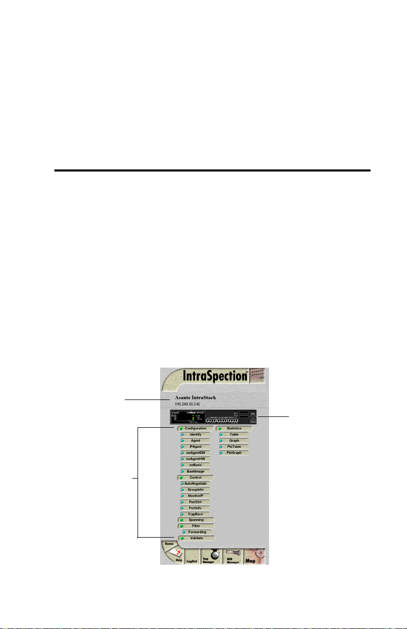
Management capabilities are accessed via the Personality Module’s
IntraSpection
IntraStack 6000 Series Personality Module
The IntraStack 6000 Series Personality Module allows for expanded
management of an Asanté IntraStack 6014DSB and any installed expansion units (such as the IntraStack 6008FX and IntraStack 6016DSE).
Device
Information
Device Page
. See Figure 1-1.
Front Panel
Image
Personality
Module
Information
Figure 1-1 IntraStack 6000 Series Device Page
Page 1-1
Page 10

Introduction
Management Options
The IntraStack 6000 Series Personality Module supports the following
management options:
Device identification
❏
information
❏
SNMP agent information
IP agent protocol infor-
❏
mation
❏
Software agent information
Hardware agent informa-
❏
tion
❏
Image bank information
Device- and group-
❏
level resets
❏
Port auto-negotiation
Group information
❏
See Chapter 5, “Menus,” for a detailed description of each management
option.
IP address monitoring
❏
❏
Port configuration and
information
Trap receivers
❏
❏
Spanning tree configu-
ration
Filter forwarding infor-
❏
mation
❏
Counter statistics
(table and graph formats) at the port-level
Packet statistics (table
❏
and graph formats) at
the port-level
Page 1-2
Page 11

IntraSpection Personality Modules
Minimum System Requirements
Server
❏
IntraSpection version 1.01 or greater
PC with 80486 or faster microprocessor
❏
❏
48MB RAM
100MB free disk space
❏
❏
Windows NT™ 3.51 or higher or Windows NT 4.0 (recommended)
Web server that supports Common Gateway Interface (CGI)
❏
1.1 (such as Netscape FastTrack Server™, Microsoft IIS,
NCSA HTTP, etc.)
❏
Any database management system that supports ODBC, such
as Microsoft Access™, Oracle™, or Microsoft SQL Server
Client
Any Windows™, Windows NT, Macintosh™ or UNIX®
❏
workstation
❏
Any World Wide Web browser with Java™ and Java Script
support such as Netscape Navigator® (version 3.0 required,
3.01 recommended), Netscape Communicator™, or
Microsoft Internet Explorer™
Page 1-3
Page 12

Page 13

2
Installation
Installing a Personality Module
This chapter explains how to install the IntraStack 6000 Series Personality Module.
Important:
▲
the computer where the IntraSpection Application
Server is installed.
Before installing the Personality Module, make sure
that IntraSpection (websuite.exe) is
the computer.
1
Insert the Personality Module CD into the computer .
2
Open the CD to display its contents.
3
Double-click the
4
Click Yes at the “IntraSpection Personality Module
Installation Confirmation” dialog box.
The IntraSpection Personality Module information
window appears.
The Personality Module is installed on
not
running on
IntraStack.exe
file.
5 Click Finish to continue.
The Personality Module files are decompressed.
The “IntraSpection Personality Module Welcome” dia-
log box appears.
6 Click Next.
The “Software License Agreement” window appears.
Review the agreement carefully.
Page 2-1
Page 14
Installation
7 Click Yes to accept the agreement and continue
with the installation.
To decline the agreement and exit the installation,
click No.
The “IntraSpection Personality Module Read Me” win-
dow appears. Review the information carefully.
8 Click Next to continue.
The decompressed Personality Module files are
installed onto your computer.
The “Decompression of the Source is Now Complete”
dialog box appears.
9 Click OK to continue with the installation.
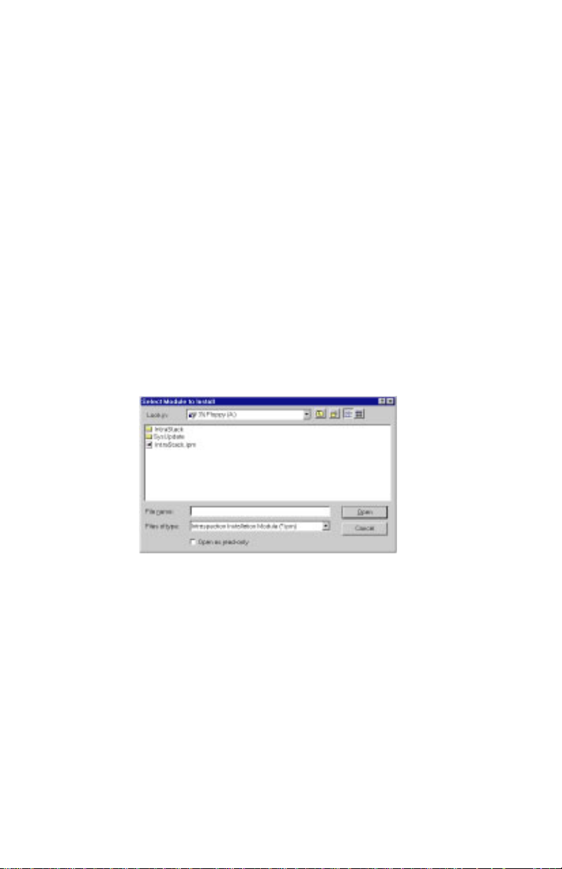
The “Select Module to Install” window appears, displaying the IntraStack.ipm file. See Figure 2-1.
Figure 2-1 Select Module to Install window
10 Click once on the IntraStack.ipm file.
11 Click Open.
The “Enter Product Serial Number” window appears.
12 Enter the serial number that came with your copy of
the Personality Module.
The serial number is located on the inside cover of this
User’s Manual.
▲ Important: The serial number is case-sensitive;
enter it exactly as shown.
Page 2-2
Page 15

Installing a Personality Module
13 Click OK.
The “IntraSpection Module Installation” window
appears.
▲ Important: This window should be pointing to
the directory that contains the IntraSpection
(websuite.exe) program. If it is not, click
Browse and locate that directory.
14 Click OK.
∆ Note: A “Select Database” window may appear.
If it does, select vendor.mdb, then click OK.
∆ Note: An “Updating IntraSpection System Files”
window may appear, if it does, click OK.
The installer program installs the IntraStack 6000
Series Personality Module into the IntraSpection Application Server.
Installation is complete when the “Installation Completed Successfully” dialog box appears.
15 Start the IntraSpection Application Server, following
the guidelines below:
❏ Windows NT 3.51 users: double-click the
IntraSpection icon (located in the Programs
group).
❏ Windows NT 4.0 users: open the Start menu, select
Programs, then IntraSpection.
For information on accessing the IntraStack for management, see Chapter 3, “Accessing the Device.”
Page 2-3
Page 16

Page 17

3
Accessing the Device
This chapter explains how to access the IntraStac k 6000 Series Personality Module’s Device Page. The Device Page provides access to the Personality Module’s management options.
Accessing the Device Page
To access the Device Page for an IntraStack, you must first create a map
of the network in IntraSpection.
1 Make sure the Personality Module is installed and the
IntraSpection Application Server is running.
2 Access IntraSpection from any Java-enabled Web
browser (requires logging into IntraSpection).
▲ Important: For help on accessing and logging
into IntraSpection, refer to the Intr
User’s Manual.
3 After you are logged into IntraSpection, click Auto-
Discovery on the IntraSpection Main Menu.
aSpection
The AutoDiscovery Page appears.
4 Complete each field on the AutoDiscovery Page, fol-
lowing the guidelines below:
❏ Type the IP subnet address of the IntraStack to
be managed in the Segment field.
❏ Type the IntraStack’s community string in the
Community field.
❏ Make sure the Enterprise ID field has a value of
all.
Page 3-1
Page 18
Accessing the Device
❏ Type the lowest (beginning) IP address on your
network in the Low IP Address field.
❏ Type the highest (last) IP address on your net-
work in the Hi IP Address field.
❏ Select New in the Discovery Mode field to create a
new map, or select Append to attach this map to
the map that is stored in your system’s buffer (if
any).
5 Click Apply.
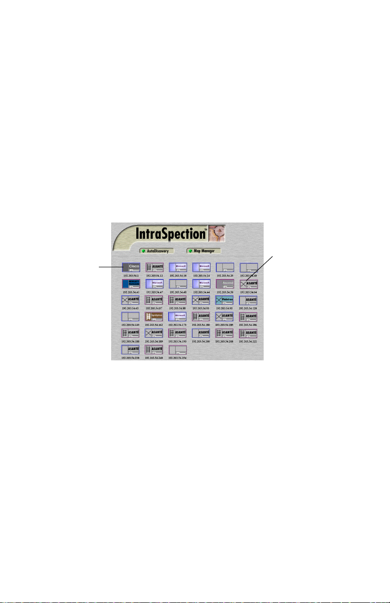
IntraSpection builds a map of your network. The map
contains icons that represent each “discovered” SNMP
device on the network. Figure 3-1 is an example map.
Device Icon
Device Symbol
Figure 3-1 Discovered network map
6 After the map is complete, click the map icon
(located at the bottom of the page on the navigation
bar) to validate the devices on the map.
∆ Note: The devices on the map are validated
when device symbols appear on certain icons.
7 Click once on the IntraStack 6000 Series’s icon.
∆ Note: This icon is labeled “Asanté” and has the
IntraStack 6000 Series’s IP address below it.
The Device Page for the IntraStack appears (see
Figure 3-2 on page 3-3).
For information on the Device Page’s components, see
“Device Page Components” on page 3-3.
Page 3-2
Page 19
Device Page Components
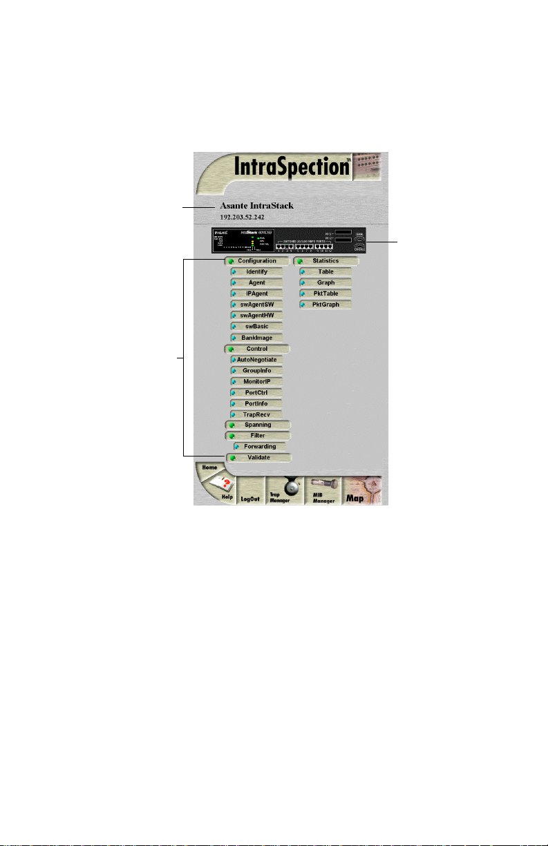
Device Page Components
A Personality Module’s Device Page consists of several components;
including, device information, a front panel image, and management
menu items. See Figure 3-2.
Device Information
Front Panel Image
Personality
Module
Information
(management
menu items)
Figure 3-2 Device Page components
Device Information
The following information is displayed at the top of the Device Page:
❏ Device description (i.e., Asanté IntraStack)
❏ Device IP address
Page 3-3
Page 20
Accessing the Device
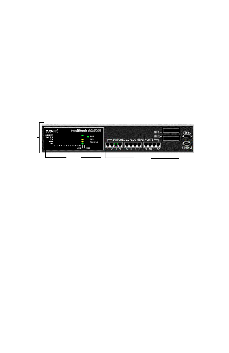
Front Panel Image
The front panel image contains the following components (as illustrated
in Figure 3-3):
❏ Device — the entire IntraStack 6000 Series switching
system (includes the IntraStack 6014DSB and any
installed expansion units).
❏ Group — each unit (module) within the device (such
as the IntraStack 6014DSB).
❏ Port — each port (including MII ports) on each group.
❏ Status LEDs — real-time LEDs that represent the LEDs
on the modules; they display port activity.
Device
LEDs
Figure 3-3 Front panel image components
Ports
▲ Important: Throughout this manual, the term device
refers to the IntraStack 6014DSB and any installed expansion units; the term group refers to an individual module
within the device stack; the term port refers to an individual port.
Group Numbering
For management purposes, each group within a device is assigned a
number:
❏ The bottom module (IntraStack 6014DSB) is group 1
❏ The next module up is group 2
❏ The top module is group 3
Port Numbering
Each port is assigned a number.
❏ Ports 1 – 12 on the IntraStack 6014DSB are referred to
as ports 1 – 12.
❏ MII (Media Independent Interface) ports I and II are
referred to as 13 and 14, respectively.
Page 3-4
Page 21

Selecting the Device for Management
Selecting the Device for Management
The IntraStack can be managed at different levels; that is, at the device,
group, or port level.
For example, if a group (such as the IntraStack 6014DSB base unit) is
selected and you select the Graph menu, statistics for that group are
displayed. If a port is selected and you select Graph, statistics for that
port are displayed.
Selecting an Item
Target Item Action
Device (entire stack) Do not click anything on the front panel
Group (single module) Click once on the group.
Port Click once on the port.
image.
Deselecting an Item
Target Item Action
Device Click once on a group or port.
Group Click again on the selected group.
Port Click again on the selected port.
Page 3-5
Page 22

Accessing the Device
Menu Components
The menus on the IntraStack 6000 Series Device Page provide access to
the different management options supported by the Personality Module.
Tables
Some menus contain tables with information that is configurable
directly on-screen from your Web browser while others contain information that is read-only. The following tables describe how to recognize
configurable and read-only information.
Configurable Information
Menu item Action
Drop-down menu Select from an available option.
White-colored fields Type information.
Read-only Information
Menu item Action
Green- or gray-colored fields None; field cannot be edited.
Table Columns
Some menus contain table columns that can be resized to fit the width
of your screen. To resize a table column, place the mouse pointer on a
column title’s left or right side (until a double arrow appears) and drag
the column to the left or to the right, as desired.
Buttons
Some menus contain buttons which allow you to edit/and or update the
page.
Button Action
Apply Applies any changes made to the device.
Refresh Updates the table with the latest information.
Modify Modifies a selected entry.
Add Adds an entry into the table.
Page 3-6
Page 23

4
Management
Performing Basic Management Functions
This chapter explains how to perform some basic management functions with the IntraStack 6000 Series Personality Module.
▲ Important: The tasks outlined in this chapter
require access to the IntraStack’s Device Page. See
Chapter 3, “Accessing the Device,” for instructions.
This chapter covers the following configuration and management tasks:
Configuration Tasks
Management Task Page
Setting community strings page 4-3
Configuring IP information page 4-5
Configuring out-of-band information page 4-6
Configuring bootstrap parameters page 4-7
Configuring device identification information page 4-8
Management Tasks
Management Task Page
Updating the Device Page page 4-9
Viewing port parameters page 4-10
Configuring port parameters page 4-11
Enabling or disabling a port page 4-14
Page 4-1
Page 24

Management
Management Task Page
Resetting the IntraStack page 4-15
Managing trap receivers page 4-16
Viewing the port address table page 4-18
Performing a software upgrade page 4-20
Downloading a configuration file page 4-23
Configuring Telnet idle time-out page 4-25
Configuring the Spanning Tree Protocol page 4-26
Viewing counter statistics (table and graph formats page 4-30
Viewing packet statistics (table and graph) formats page 4-33
Page 4-2
Page 25
Setting Community Strings
Setting Community Strings
Community strings define access rights for reading and writing SNMP
data objects for a device.
The community strings (read and write) for an IntraStack are manually
set in the IntraStack 6014DSB via the unit’s console port.
In order to access an IntraStack with IntraSpection, the community
strings must be set in IntraSpection to match those set in the IntraStack
6014DSB.
▲ Important: It is recommended that you set the commu-
nity strings for an IntraStack 6014DSB in IntraSpection
before you attempt to perform any network management
functions.
This section describes how to set the community strings in IntraSpection to match those set in the IntraStack 6014DSB.
To set the community strings in IntraSpection:
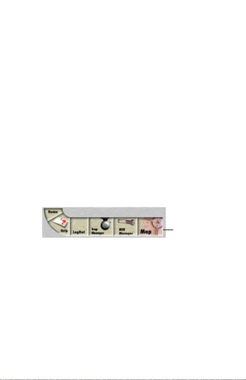
1 On the Device Page, click the map icon on the
IntraSpection navigation bar (located at the bottom of
the screen), as shown in Figure 4-1.
Figure 4-1 IntraSpection navigation bar
The most recently discovered map appears.
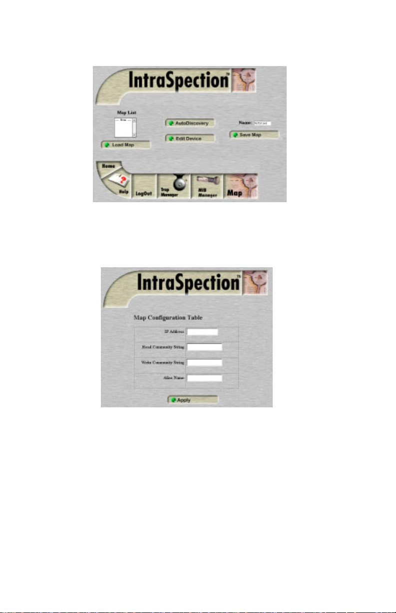
2 Click the Map Manager button.
The Map Manager Page appears, similar to Figure 4-2.
Map Icon
Page 4-3
Page 26
Management
Figure 4-2 IntraSpection Map Manager Page
3 Click the Edit Device button.
The Map Configuration table appears, similar to Figure 4-3.
Figure 4-3 Map Configuration table
4 Enter the IntraStack 6014DSB’s IP address in the IP
Address field.
5 Enter the IntraStack 6014DSB’s read community
string in the Read Community String field.
6 Enter the IntraStack 6014DSB ‘s write community
string in the Write Community String field.
7 Click Apply.
The read and write community strings for the IntraStack
6014DSB are configured.
Page 4-4
Page 27
Configuring IP Information
Configuring IP Information
To configure and/or manage an IntraStack over the network, the IntraStack 6014DSB needs to be properly configured with IP information (such
as the device’s IP address, subnet mask, and default gateway address).
This information is initially set-up in the IntraStack 6014DSB via the
unit’s console port; however, some information can be modified using
IntraSpection.
To configure the IntraStack 6014DSB’s IP information:
1 Do not select any item on the Device Page’s front-panel
image. (This selects the entire device.)
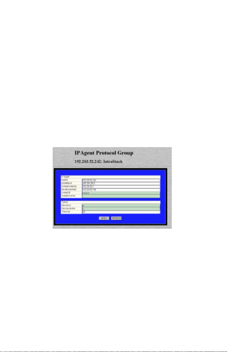
2 Click IPAgent.
The IP Agent Protocol Group table appears, similar to Figure 4-4.
Figure 4-4 IP Agent Protocol Group table
3 Click once in the IP Agent field to be edited.
▲ Important: Only those fields that are colored
white can be edited.
For a description of each field, see “IP Agent “ on page 5-7.
4 Type the new information.
5 Click Apply.
The IntraStack’s IP information is configured. Click
Refresh to view updated information.
Page 4-5
Page 28
Management
Configuring Out-of-Band Information
You can configure an IntraStack’s out-of-band parameters (i.e., the dialstring and baud rate) via the Agent menu.
To configure an IntraStack’s out-of-band information:
1 Do not select any item on the Device Page’s front-panel
image. (This selects the entire device.)
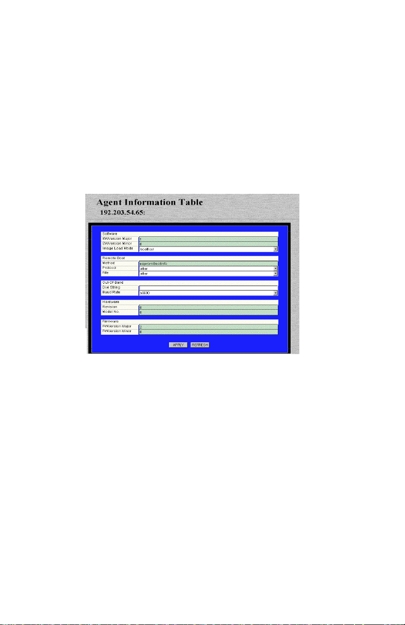
2 Click Agent.
The Agent Information table appears, similar to Figure 4-5.
Figure 4-5 Agent Information table
∆ Note: For a description of each field, see “Agent”
on page 5-5.
3 To change the IntraStack’s out-of-band dial string,
click once in the Dial String field and type the dial
string.
4 To change the IntraStack’s out-of-band baud rate,
open the Baud Rate drop-down menu and select a
new baud rate.
5 Click Apply.
The IntraStack 6014DSB’s out-of-band information is configured.
Click Refresh to view updated information.
Page 4-6
Page 29

Configuring Bootstrap Parameters
Configuring Bootstrap Parameters
Y ou can determine the method (local or remote) that the IntraStac k uses
to load its software at startup or during a reset via the Agent menu.
To configure the IntraStack’s bootstrap parameters:
1 Do not select any item on the Device Page’s front-panel
image. (This selects the entire device.)
2 Click Agent.
The Agent Information table appears, similar to Figure 4-5
on page 4-6.
∆ Note: For a description of each field, see “Agent”
on page 5-5.
3 Open the Image Load Mode field and select one of
the following options:
❏ localBoot — sets the IntraStack 6014DSB to
execute its software image file from its internal
flash memory.
❏ netBoot — sets the IntraStack 6014DSB to load
its software image file from a server on the network.
4 Click Apply.
The IntraStack 6014DSB’s bootstrap parameters are configured.
Page 4-7
Page 30
Management
Configuring Device Identification Information
To help with identification, you can add certain details about the IntraStack; such as, the device’s name, location, and contact information.
To configure device identification information:
1 Do not select any item on the Device Page’s front-panel
image. (This selects the entire device.)
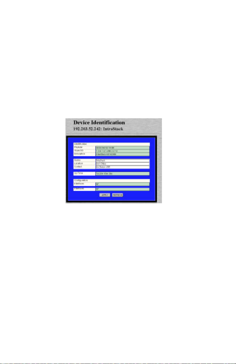
2 Click Identify.
The Device Identification table appears, similar to Figure
4-6.
Figure 4-6 Device Identification table
3 Click once in the Name, Location or Contact field
to be edited.
∆ Note: For a description of all the fields, see
“Identify “ on page 5-4.
▲ Important: Only those fields that are colored
white can be edited.
4 Type the new information.
A maximum of 254 characters (including spaces) is
allowed.
5 Click Apply .
The IntraStack’s identification information is configured.
Click Refresh to view updated information.
Page 4-8
Page 31

Updating the Device Page
Updating the Device Page
The files for the IntraStack 6000 Series Personality Module are stored
within the IntraSpection Application Server’s database.
Occasionally, these files should be updated from the Device Page to
ensure that you are viewing the IntraStack’s latest information.
To update the Personalty Module’s Device Page:
1 Click Validate.
The Device Page is updated with the latest information for
the Personalty Module.
After the Device Page is updated, the IntraSpection Map
Manager Page appears.
2 Click AutoDiscovery to r ediscover the networ k map
containing the IntraStack.
▲ Important: See “Accessing the Device Page” on
page 3-1 for instructions creating a network map.
Page 4-9
Page 32

Management
Viewing Port Parameters
You can view information about each port within an IntraStack switching system via the PortInfo menu.
The PortInfo (Port Information) menu displays the type of eac h port as
well as the port’s auto-negotiation status, link status, speed, and duplex
mode.
To view port parameters:
1 Click PortInfo.
You do not have to select any particular port on the frontpanel image.
The Port Information table appears, similar to Figure 4-7.
Figure 4-7 Port Information table
The table displays information about each of the IntraStack’s ports.
Each port is identified by its group number (GrpIndex)
and its port number (Index).
∆ Note: For a description of each field, see “Port-
Info” on page 5-21.
2 Click Refresh to view updated information.
Page 4-10
Page 33

Configuring Port Parameters
Configuring Port Parameters
You can configure each port within an IntraStack for the following:
❏ Auto-negotiation
❏ Broadcast filtering
❏ Store-and-forwarding
▲ Important: You cannot configure a port’s duplex
mode via the Personality Module.
Configuring Auto-Negotiation
Auto-negotiation allows two devices on a common segment to communicate their capabilities, allowing the devices to determine their highest
common speed and best communication parameters.
The options negotiated during auto-negotiation are: Ethernet type
(100Base-TX or 10Base-T) and duplex mode (half or full).
▲ Important: To use auto-negotiation, both devices
must support the auto-negotiation feature.
To configure a port for auto-negotiation:
1 Click AutoNegotiate.
You do not have to select any particular port on the frontpanel image.
The Port Auto-Negotiation table appears, similar to
Figure 4-8.
Figure 4-8 Port Auto-Negotiation table
Page 4-11
Page 34

Management
2 Click once on the row of the port you want to config-
ure.
The ports are identified by their group number (GrpIndex)
and port number (PortIndex).
∆ Note: For a description of each field, see “Auto
Negotiate” on page 5-15.
3 Click Modify.
The “Modify Dialog” box appears.
4 Open the Admin State drop-down menu and select
enable.
5 Click Apply.
The port is configured for auto-negotiation.
Configuring Broadcast Filtering
Broadcast filtering is a port’s ability to control the forwarding of broadcast packets.
If enabled, broadcast packets are discarded. If disabled, broadcast packets are processed normally.
To configure a port’s broadcast filtering ability:
1 Click PortCtrl.
You do not have to select any port on the front-panel image.
The Port Control table appears.
2 Click once on the row of the port you want to config-
ure.
3 Click Modify.
The “Modify Dialog” box appears.
4 Open the Filter drop-down menu and select Enable.
5 Click Apply.
The port is configured for broadcast filtering.
Page 4-12
Page 35

Configuring Port Parameters
Configuring Store-and-Forwarding
Store-and-forwarding is a port’s ability to store incoming packets before
forwarding them.
To configure a port’s store-and-forwarding ability:
1 Click PortCtrl.
You do not have to select any port on the front-panel
image.
The Port Control table appears.
2 Click once on the row of the port you want to config-
ure.
3 Click Modify.
The “Modify Dialog” box appears.
4 Open the StNFw drop-down menu and select
Enable.
5 Click Apply.
The port is configured for store-and-forwarding.
Page 4-13
Page 36

Management
Enabling or Disabling a Port
The enabling or disabling of a port is a manual operation that can be
used to isolate network devices possibly causing problems on the network. It can also be used to prevent unauthorized use of a port or station.
To enable or disable a port:
1 Click PortCtrl.
You do not need to select any particular item on the frontpanel image.
The Port Control table appears, similar to Figure 4-9.
Figure 4-9 Port Control table
∆ Note: For a description of each field, see “Port
Ctrl” on page 5-19.
2 Select the port to be enabled or disabled by clicking
once on the port’s row.
3 Click Modify.
The “Modify Dialog” box appears.
4 Open the State drop-down menu and select Enable
(to enable the port) or Disable (to disable the port).
5 Click Apply.
The port’s state is modified. Click Refresh to view updated
information.
Page 4-14
Page 37

Resetting the IntraStack
Resetting the IntraStack
You can reset the entire IntraStack device or a selected group via the
Reset menu.
To perform a reset:
1 To reset the device, do not select anything on the front-
panel image.
To reset a group, click once the group.
2 Click Reset.
The Reset table appears for the agent or a selected group,
similar to Figure 4-10 or Figure 4-11.
Figure 4-10 Reset Agent table (device reset)
Figure 4-11 Reset Group table (group reset)
3 Open the Action drop-down menu and select reset.
4 Click Apply.
The IntraStack 6000 Series switch (or the selected group) is
reset.
▲ Important: To abort the reset, click on the
browser’s back arrow to go back one page.
Page 4-15
Page 38

Management
Managing Trap Receivers
Trap receivers are the network management stations designated to
receive traps from the IntraStack when they occur.
▲ Important: A maximum of four trap receivers is
allowed.
This section describes how to add and delete a trap receiver.
To add a trap receiver entry:
1 Do not select any item on the Device Page’s front-panel
image. (This selects the entire device.)
2 Click TrapRecv.
The Trap Receiver table appears, similar to Figure 4-12.
Figure 4-12 Trap Receiver table
∆ Note: For a description of each field, see “Trap
Recv” on page 5-22.
If there are no entries, the table is blank.
3 Click Add.
The Add Dialog box appears.
4 Open the Status drop-down menu and select valid.
5 Type the IP address of the manag ement station that is
to receive traps in the Trap Receiver Address field.
▲ Important: Do NOT type an IP address of
0.0.0.0.
Page 4-16
Page 39

Managing Trap Receivers
6 Type the community string for the management sta-
tion in the Community String field.
7 Click Apply.
The entry for the management station is added and appears
in the table. If it does not appear, click Refresh.
Deleting a Trap Receiver Entry
To delete a trap receiver entry:
1 Click once on the row containing the entry to be
deleted.
2 Click Modify.
The “Modify Dialog” box appears.
3 Open the Status drop-down menu and select
invalid.
4 Click Apply.
The trap receiver’ entry is deleted.
Click Refresh to view updated information.
Modifying a Trap Receiver Entry
To change the IP address of a trap receiver entry:
1 Delete the trap receiver entry, following the directions
above.
2 Add a new trap receiver entry, following the instruc-
tions on page 4-16.
The trap receiver entry’s IP address is changed.
Click Refresh to view updated information.
Page 4-17
Page 40

Management
Viewing the Port Address Table
The IP Address Monitoring Table is a table of node addresses that the
IntraStack automatically builds by listening to and learning the information that is broadcast when a new node logs on.
The IntraStack checks the source and destination addresses as packets
pass through it and records the source address information in the table.
The IntraStack uses the information in this table to decide whether a
frame should be forwarded or filtered. Each entry consists of the MAC
address of the device and an identifier for the port on which it was
received.
To view the IntraStack’s IP address table:
1 Do not select any item on the front-panel image. (This
selects the entire device).
2 Click MonitorIP.
The IP Address Monitoring table appears, similar to Figure
4-13.
Page 4-18
Figure 4-13 IP Address Monitoring table
The table automatically sorts entries numerically by their IP
address.
Page 41

Viewing the Port Address Table
You can change the sorting order in which information is
displayed by click once on one of the following buttons:
❏ Grp, Port, IP — sorts by group number, port
number, then IP address.
❏ Grp, Port, Physical — sorts by group number,
port number, then physical address.
❏ Phys, Grp, Port — sorts by physical address,
group number, then port number.
∆ Note: The information displayed in the IP
Address Monitoring Table is read-only.
∆ Note: For a description of each field, see “Moni-
tor IP” on page 5-18.
3 Click Refresh to view updated information.
Page 4-19
Page 42

Management
Performing a Software Upgrade
An IntraStack’s software image file can be upgraded via IntraSpection.
To upgrade an IntraStack’s software image file requires two steps:
❏ Set up the IntraStack 6014DSB’s boot information.
❏ Configure the image file information.
Set up the Boot Information
To set up the IntraStack 6014DSB’s boot information:
1 Click Agent.
The Agent Information table appears.
2 Open the Image Load Mode drop-down menu and
select netBoot.
This sets the IntraStack 6014DSB to boot (download its soft-
ware) over the network from a remote server.
3 Open the Protocol drop-down menu and select
bootp-tftp or tftp.
This sets the IntraStack to download the software image file
through TFTP (trivial transfer file protocol).
4 Click once in the File field and type the name and
network path of the software image file.
5 Click Apply.
The IntraStack’s boot information is configured. Next, configure the image file information following the instructions
below.
Configure the Image File Information
1 Click swAgentSW.
The Switch Agent Software Group table appears, similar to
Figure 4-14.
Page 4-20
Page 43

Performing a Software Upgrade
Figure 4-14 Switch Agent Software Group table
∆ Note: For a description of each field, see
“swAgentSW” on page 5-9.
2 Open the Up/Download Action drop-down menu
and select Download.
3 Open the Download File drop-down menu and
select Image-File.
4 Type the server’s IP address where the software file
resides in the Image Server field.
5 Type the name and network path of the image file in
the Image File Name field.
6 Type the number of attempts the IntraStack will
make to download the file in the Image Retries
field.
7 Open the Active Image Bank drop-down menu and
select the image bank that will receive the downloaded image file.
∆ Note: The IntraStack 6014DSB has two image
areas (or “banks”) where its runtime software is
stored:
Page 4-21
Page 44

Management
8 Click Apply.
The IntraStack downloads the image file to the image bank
specified.
Click Refresh to view updated information.
❏ Active Image Bank — the bank that is used dur-
ing the system boot-up (also referred to as “Boot
Bank”
❏ Download Bank — the bank that receives the
new version of runtime code when it is downloaded (also referred to as “Destination Bank”).
Page 4-22
Page 45

Downloading a Configuration File
Downloading a Configuration File
The IntraStack’s configuration file can be downloaded to the device via
IntraSpection.
To download a configuration file:
1 Make sure the IntraStack is configured with valid boot
information.
See “Set up the Boot Information” on page 4-20 for instruc-
tions.
2 Click swAgentSW.
The Switch Agent Software Group table appears.
3 Open the Up/Download Action drop-down menu
and select Download.
4 Open the Download File drop-down menu and
select Config-File.
5 Type the server’s IP address where the configuration
file resides in the Config Server field.
6 Type the name of the configuration file in the Config
File Name field.
7 Type the number of attempts the IntraStack will
make to download the file in the Config Retries
field.
8 Open the Active Image Bank drop-down menu and
select the image bank that will receive the downloaded configuration file.
∆ Note: The IntraStack 6014DSB has two image
areas (or “banks”) where its runtime software is
stored:
❏ Active Image Bank — the bank that is used
during the system boot-up (also referred to as
“Boot Bank”
❏ Download Bank — the bank that receives the
new file when it is downloaded (also referred to
as “Destination Bank”).
Page 4-23
Page 46

Management
9 Click Apply.
The IntraStack downloads the configuration file to the
image bank specified.
Click Refresh to view updated information.
Page 4-24
Page 47

Configuring Telnet Idle Time-Out
Configuring Telnet Idle Time-Out
You can configure the amount of time an idle Telnet connection to the
IntraStack remains active via the swAgentSW menu.
If a Telnet connection to the IntraStack remains idle for the number of
specified time-out minutes, the remote Telnet connection to the IntraStack is automatically disabled.
To configure the IntraStack’s Telnet idle time-out:
1 Do not select anything on the front-panel image. (This
selects the entire device).
2 Click swAgentSW.
The Switch Agent Software Group table appears, similar to
Figure 4-15.
Figure 4-15 Switch Agent Software Group table
∆ Note: For a description of each field, see
“swAgentSW” on page 5-9.
3 Type the number of minutes for the time-out period
in the Telnet TimeOut field.
4 Click Apply.
The Telnet idle time-out period is configured.
Page 4-25
Page 48

Management
Configuring the Spanning Tree Protocol
The IntraStack is shipped with Spanning Tree enabled on all ports.
You can disable or enable Spanning Tree on the IntraStack or on an indi-
vidual port. You can also configur e the Spanning T r ee parameters on the
IntraStack.
▲ Important: Do not enable, disable, or configure the
Spanning Tree Parameters unless you have knowledge
and experience with the IEEE 802.1d specification.
Disabling or Enabling Spanning Tree
You can disable or enable Spanning Tree on the IntraStack or on an individual port.
To disable or enable Spanning Tree on the IntraStack:
1 Click swAgentSW.
The Switch Agent Software Group table appears.
2 Open the STP drop-down menu and select Disable
(to disable Spanning Tree on the IntraStack) or
Enable (to enable Spanning Tree on the IntraStack).
3 Click Apply.
Spanning Tree is disabled (or enabled) on the IntraStack.
To disable or enable Spanning Tree on a port:
1 Click PortCtrl.
The Port Control table appears, similar to Figure 4-16.
Page 4-26
Page 49

Configuring the Spanning Tree Protocol
Figure 4-16 Port Control table
2 Select the port you want to disable or enable Span-
ning Tree on by clicking once on its row.
3 Click Modify.
The “Modify Dialog” box appears.
4 Open the STP drop-down menu and select Disable
(to disable Spanning Tree on the port) or Enable (to
enable Spanning Tree on the port).
5 Click Apply.
Spanning Tree is disabled (or enabled) on the selected port.
Page 4-27
Page 50

Management
Configuring Spanning Tree Parameters
To configure the Spanning Tree Parameters on the IntraStack:
▲ Important: Do not change an y of the Spanning T ree
parameters unless you have knowledge and e xperience
with the IEEE 802.1d specification.
1 Do not select any item on the front-panel image. (This
selects the entire device.)
2 Click Spanning.
The Spanning Tree Device table appears, similar to
Figure 4-17.
Figure 4-17 Spanning Tree Device table
∆ Note: For a description of each field, see “Span-
ning” on page 5-23.
3 Within this table, you can configure the following
information:
❏ Spanning Tree Priority
❏ Bridge Maximum Age
❏ Bridge Hello Time
❏ Bridge Forward Delay
4 Click once in the Spanning Tree par ameter field to be
modified.
Page 4-28
Page 51

Configuring the Spanning Tree Protocol
5 Type the new information.
6 Click Apply.
The Spanning Tree parameters on the IntraStack are configured.
Click Refresh to view updated information.
Page 4-29
Page 52

Management
Viewing Statistics
There are two groups of statistics with the IntraStack 6000 Series Personality Module:
❏ Counter Statistics (such as broadcast packets, frag-
ments, and collisions)
❏ Packet Statistics
Both groups of statistics can be viewed in two differ ent formats: table or
graph.
▲ Important: Statistics are available at the port-level
only.
This section describes how to view counter and packet statistics in both
table and graph formats.
Viewing Counter Statistics (Table Format)
To view counter statistics in a table format:
1 Select a port for which statistics are to be gathered by
clicking on it once..
▲ Important: Statistics can be viewed at the port-
2 Click Table.
Counter statistics appear for the selected port, similar to
Figure 4-18.
Figure 4-18 Counter Statistics (table format)
For a description of each object, see “Objects” on page 5-
27.
Page 4-30
level only.
Page 53

3 Open the Sampling Interval drop-down menu and
select the number of seconds to poll for statistics.
Statistics are automatically gathered at the selected interval
in the following columns:
❏ Curr — (current) the number of occurrences each
second.
❏ Peak — the largest number of occurrences since
opening or resetting the screen.
❏ Avg — (average) the average number of occurrences
since opening or resetting the screen.
❏ Total — the total number of occurrences since open-
ing or resetting the screen.
4 Click Reset to reset the counters to zero.
Viewing Counter Statistics (Graph Format)
To view counter statistics in a graph format:
Viewing Statistics
1 Select a port for which statistics are to be gathered by
clicking on it once on the front-panel image.
▲ Important: Statistics can be viewed at the port-
level only.
2 Click Graph.
Counter statistics appear for the selected port, similar to
Figure 4-19.
Page 4-31
Page 54

Management
Count-PerSecond
Display
Figure 4-19 Counter Statistics (graph format)
3 Open the Statistics drop-down menu and select the
object to be monitored.
For a description of each object, see “Objects” on page 5-
27.
4 Open the Seconds drop-down menu and select the
number of seconds for which statistics are to be gathered.
5 Use the scroll button to change the gr aph’s count-per-
second display (scroll up to increase the count-persecond, scroll down to decrease it).
❏ Average per Second — the average number of
occurrences since opening or resetting the
screen.
Scroll Bar
Drop-Down
Menus:
Seconds
Statistics
❏ Peak per Second — the largest number of occur-
rences since opening or resetting the screen.
6 Click Reset to reset the counters to zero.
Page 4-32
Page 55

Viewing Packet Statistics (Table Format)
To view packet statistics in a table format:
1 Select a port for which statistics are to be gathered by
clicking on it once.
▲ Important: Statistics can be viewed at the port-
level only.
2 Click PktTable.
Packet statistics appear for the selected port, similar to Figure 4-20.
Viewing Statistics
Figure 4-20 Packet Statistics (table format)
For a description of each object, see “Objects” on
page 5-30.
3 Open the Sampling Interval drop-down menu and
select the number of seconds to poll for statistics.
Statistics are automatically gathered at the selected interval
in the following columns:
❏ Curr — (current) the number of occurrences each
second.
❏ Peak — the largest number of occurrences since
opening or resetting the screen.
❏ Avg — (average) the average number of occurrences
since opening or resetting the screen.
❏ Total — the total number of occurrences since open-
ing or resetting the screen.
4 Click Reset to reset the counters to zero.
Page 4-33
Page 56

Management
Viewing Packet Statistics (Graph Format)
To view packet statistics in a graph format:
1 Select a port for which statistics are to be gathered by
clicking on it once on the front-panel image.
▲ Important: Statistics can be viewed at the port-
level only.
2 Click PktGraph.
Packet Statistics appears for the selected port, similar to Figure 4-21.
Count-PerSecond
Display
Figure 4-21 Packet Statistics (graph format)
3 Open the Statistics drop-down menu and select the
object to be monitored.
For a description of each object, see “Objects” on page 5-
30.
4 Open the Seconds drop-down menu and select the
number of seconds for which statistics are to be gathered.
5 Use the scroll button to change the gr aph’s count-per-
second display (scroll up to increase the count-persecond, scroll down to decrease it).
❏ Average per Second — the average number of
occurrences since opening or resetting the
screen.
Scroll Bar
Drop-Down
Menus:
Seconds
Statistics
Page 4-34
Page 57

❏ Peak per Second — the largest number of occur-
rences since opening or resetting the screen.
6 Click Reset to reset the counters to zero.
Viewing Statistics
Page 4-35
Page 58

Page 59

5
Menus
This chapter describes each management menu on the IntraStack 6000
Series’s Device Page.
The table below provides a brief description of each menu; the sections
that follow explain each menu in detail.
Table 5-1 Device Page Menu Descriptions
Menu Description
Configuration Title for the submenus listed below it; this menu cannot be
selected. See “Configuration” on page 5-4.
Identify Allows you to view and configure device identification
information. See “Identify” on page 5-4.
Agent Allows you to view agent information. Also allows you to
configure the device’s image load mode, remote boot information, and out-of-band dial string and baud rate. See
“Agent” on page 5-5.
IPAgent Allows you to view and configure the IP address, default
gateway, and boot server address for the device. Also
allows you to set the Telnet idle time-out period. See
“IPAgent” on page 5-7.
swAgentSW Allows you to view and configure the information needed
for downloading a new image file or configuration file. Also
allows you to enable or disable the Spanning T ree Protocol.
See “swAgentSW” on page 5-9.
swAgentHW Allows you to view hardware information on the device’s
SNMP agent (such as DRAM and EEPROM size). See
“swAgentHW” on page 5-11.
swBasic Allows you to view basic information (such as the back-
plane type and group capacity) on the device or a particular
group. See “swBasic” on page 5-12.
Page 5-1
Page 60

Menus
Menu Description
BankImage Allows you to view the latest information on the device’s
two image banks. See “BankImage” on page 5-13.
Control Title for the sub-menus listed below it; this menu cannot be
selected. See “Control” on page 5-14.
Reset Allows you to reset the device or a selected group. See
“Reset” on page 5-14.
AutoNegotiate
GroupInfo Allows you to view information about each group within the
MonitorIP Allows you to view the device’s IP Address Monitoring
PortCtrl Allows you to enable or disable the following: a port, port
PortInfo Allows you to view general port information (such as port
TrapRecv Allows you to view, add, and delete trap receiver entries.
Spanning Allows you to view and configure the Spanning Tree Proto-
Filter Title for the sub-menu listed below it; this menu cannot be
Forwarding Allows you to view filter forwarding information on the
Allows you to view and configure port configuration information (including enabling/disabling a port and restarting a
port’s auto-negotiation ability). See “AutoNegotiate” on
page 5-15.
device. Also allows you to enable or disable a selected
group. See “GroupInfo” on page 5-17.
table, which displays the last addresses learned by the
device. See “MonitorIP” on page 5-18.
filtering, store-and-forwarding, or the Spanning Tree Protocol on a particular port. See “PortCtrl” on page 5-19.
type, auto-negotiation status, and port speed) for each port.
See “PortInfo” on page 5-21.
See “TrapRecv” on page 5-22.
col. See “Spanning” on page 5-23.
selected. See “Filter” on page 5-26.
device. See “Forwarding” on page 5-26.
Validate Updates the Device Page with the latest information from
the IntraSpection Application Server database. See “Validate” on page 5-27.
Statistics Title for the submenus listed below it; this menu cannot be
selected. See “Statistics” on page 5-27.
Table Allows you to view real-time counter statistics, in a table
format, on a selected port. See “Table” on page 5-27.
Page 5-2
Page 61

Menu Description
Graph Allows you to view real-time counter statistics, in a graph
format, on a selected port. See “Graph” on page 5-29.
PktTable Allows you to view real-time packet statistics, in a table for-
mat, on a selected port. See “PktTable” on page 5-30.
PktGraph Allows you to view real-time packet statistics, in a graph
format, on a selected port. See “PktGraph” on page 5-31.
Page 5-3
Page 62

Menus
Configuration
This menu is not a management option; it is a title for the configuration
sub-menus listed below it. This menu CANNOT be selected.
Identify
This menu provides read-only and configurable identification information for the device.
Table 5-2 describes each field in the Identify menu.
∆ Note: For instructions on using this menu, see “Config-
uring Device Identification Information” on page 4-8.
Table 5-2 Identify Menu
Field Description
PhyAddr Read-only field; displays the device’s hardware
address.
ObjectID Read-only field; displays the device’s SNMP identify-
ing number.
Description Read-only field; displays a description of the device.
Name Configurable field; assigns a name to the device.
Note:
A maximum of 254 characters (including
spaces) is allowed.
Location Configurable field; assigns a location to the device.
Note:
A maximum of 254 characters (including
spaces) is allowed.
Contact Configurable field; assigns a name of the person
responsible for the device.
Note:
A maximum of 254 characters (including
spaces) is allowed.
Up Time Read-only field; displays the amount of time the
device has been operational since the last time it was
off-line (in days, hours, minutes, and seconds).
Interfaces Read-only field; displays the number of network inter-
faces present on the device.
Page 5-4
Page 63

Agent
Agent
This menu displays read-only and configurable SNMP agent information
for the device; including; the image load method and protocol and the
out-of-band dial string and baud rate.
Table 5-3 describes each field in the Agent menu.
∆ Note: For instructions on using this menu, see “Config-
uring Out-of-Band Information” on page 4-6 and “Configuring Bootstrap Parameters” on page 4-7.
Table 5-3 Agent Menu
Field Description
SWVersion Major Read-only field; displays the major software version
number of the agent runtime image.
SWVersion Minor Read-only field; displays the minor software version
number of the agent runtime image.
Image Load Mode Configurable field; determines if the device is to load
the software image from its internal FLASH EPROM or
from the network.
❏ localBoot — the software image is loaded
from the device’s FLASH EPROM.
❏ netBoot — the software image is loaded from
the network.
Method Read-only field; displays the method for getting boot
parameter information (always displays eeprom-
BootInfo [use EEPROM boot parameters]).
Protocol Configurable field; determines the method used for
requesting the software image file from the network.
❏ bootp-tftp — the device requests an IP
address from a BootP server and downloads
the software image file through TFTP (trivial
transfer protocol).
❏ tftp — the device only downloads the soft-
ware image file through TFTP (an IP address is
not requested).
File Configurable field; determines the name and network
path of the software image file.
Dial String Configurable field; determines the initialization string
used by the network management station to establish
an out-of-band connection (such as a modem).
Page 5-5
Page 64

Menus
Field Description
Baud Rate Configurable field; determines the baud rate setting
for the out-of-band port.
❏ b1200 — 1200 baud rate
❏ b2400 — 2400 baud rate
❏ b4800 — 4800 baud rate
❏ b9600 — 9600 baud rate
❏ b19200 — 19200 baud rate
Revision Read-only field; displays the hardware reversion num-
ber of the device.
Model No. Read-only field; displays the hardware model number
of the device.
FWVersion Major Read-only field; displays the major firmware version
number of the agent prom code.
FWVersion Minor Read-only field; displays the minor firmware version
number of the agent prom code.
Page 5-6
Page 65

IP Agent
IP Agent
This menu displays read-only and configurable IP (Internet Protocol)
agent information for the device; including, the device’s IP address, subnet mask, default gateway, and Telnet information.
Table 5-4 describes each field in the IP Agent menu.
∆ Note: For instructions on using this menu, see “Config-
uring IP Information” on page 4-5.
Table 5-4 IP Agent Menu
Field Description
IpAddr Configurable field; determines the IP address of the
agent.
▲ Important: This parameter only takes effect after
an agent restart or reset.
IpNetMask Configurable field; determines the IP subnet mask of
the agent.
▲ Important: This parameter only takes effect after
an agent restart or reset.
DefaultGateway Configurable field; determines the default gateway IP
address of the agent.
▲ Important: This parameter only takes effect after
an agent restart or reset.
BootServerAddr Configurable field; determines the IP address of the
boot server that was used for booting this agent.
▲ Important: This parameter only takes effect after
an agent restart or reset.
UnAuthIP Read-only field; displays the IP address of the last sta-
tion that tried to access this device with an invalid
community string.
UnAuthComm Read-only field; displays the community string of the
last station that tried to access this device with an
invalid community string.
Sessions Read-only field; displays the number of simultaneous
Telnet sessions that can be used to access the device
for management.
SessionsActive Read-only field; displays the number of currently
active Telnet sessions.
Page 5-7
Page 66

Menus
Field Description
TimeOut Configurable field; determines the Telnet idle time-out
period.
Note: The default is 20 minutes.
Page 5-8
Page 67

swAgentSW
swAgentSW
This menu displays configurable and read-only software information for
the device’s SNMP agent. It allows y ou to download a ne w image file or
configuration file and enable or disable the Spanning Tree Protocol.
Table 5-5 describes each field in the swAgentSW menu.
∆ Note: For instructions on using this menu, see “Per-
forming a Software Upgrade” on page 4-20 and “Downloading a Configuration File” on page 4-23.
Table 5-5 swAgentSW Menu
Field Description
Up/Download
Action
Configurable field; displays the agent’s current
uploading or downloading action (for either the configuration file or the image file).
❏ off — the agent is not in the up/download
mode.
❏ Download — the agent is in the downloading
mode.
❏ Upload — the agent is in the uploading mode
(this action is only for the configuration file).
Up/Download
Status
Read-only field; displays the agent’s last uploading or
downloading action (for either the configuration file
or the image file).
❏ Action-Success — the up/download was suc-
cessful.
❏ Action-Failure — the up/download failed.
❏ In-Progress — up/download is in progress.
❏ No-Action — no up/download was attempted.
Download File Configurable field; determines which file (either the
configuration file or image file) to be downloaded.
Config Server Configurable field; determines the IP address of the
configuration file server. This IP address is specific for
the configuration file up/download server.
Config FileName Configurable field; determines the name and network
path of the device configuration file.
Config Retires Configurable field; determines the number of
attempts that will be made for downloading the configuration file.
Page 5-9
Page 68

Menus
Field Description
Image Server Configurable field; determines the IP address of the
image file server. This IP address is specific for the
agent image file download server.
Image File Name Configurable field; determines the name and network
path of the image file.
Image Retries Configurable field; determines the number of
attempts that will be made for downloading the image
file.
Active Image Bank Configurable field; determines the image bank for the
next boot-up.
Note: The IntraStack has two areas (or “banks”)
where its runtime software is stored (the Active Image
Bank and Download Bank).
Download Bank Read-only field; displays the number of the current
download image bank.
Reset Wait Configurable field; determines the amount of time the
system waits before performing a reset.
▲ Important: This value can be from 0 seconds to
86400 seconds (24 hours).
Reset Left Read-only field; displays the amount time remaining
until the system performs a reset.
Telnets Read-only field; displays the number of Telnet ses-
sions that can be used to access the device for management.
TelnetsActive Read-only field; displays the number of currently
active Telnet sessions.
Telnet TimeOut Configurable field; determines the Telnet idle time-out
period.
Note: The default is 20 minutes.
STP Configurable field; enables or disables the Spanning
Tree Protocol on the device.
Page 5-10
Page 69

swAgentHW
swAgentHW
This menu displays read-only hardware information for the device’s
SNMP agent.
Table 5-6 describes each field in the swAgentHW menu.
Table 5-6 swAgentHW Menu
Field Description
DRAMSize Read-only field; displays the DRAM size (in bytes) on
the device’s hardware board.
FlashRAMSize Read-only field; displays the FlashRAM size (in bytes)
on the device’s hardware board.
EEPROMSize Read-only field; displays the EEPROM size (in bytes)
on the device’s hardware board.
Page 5-11
Page 70

Menus
swBasic
This menu displays read-only information on the device; such as, its
backplane type and group capacity.
Table 5-7 describes each field in the swBasic menu.
Table 5-7 swBasic Menu
Field Description
Type Read-only field; displays the Ethernet switch type.
Back Plane Type Read-only field; displays the back plane of this device.
Group Capacity Read-only field; displays the number of groups that
can be contained within the device.
StackLastChange Read-only field; displays the sysUpTime value of the
last change of stack status since the entire stack has
been in operation.
If no change has occurred since the stack has been in
operation, the value displayed is 0s.
Page 5-12
Page 71

BankImage
BankImage
This menu displays read-only information on the device’s two image
banks.
Table 5-8 describes each field in the BankImage menu.
Table 5-8 BankImage Menu
Field Description
Index Read-only field; displays the number of the entry in
the BankImage Table.
MajorVersion Read-only field; displays the major version number of
the bank image software.
MinorVersion Read-only field; displays the minor version number of
the bank image software.
Date Time Read-only field; displays the date and time of the bank
image software.
Page 5-13
Page 72

Menus
Control
This menu is not an actual management option; it is a title to the submenus listed below it. This menu CANNOT be selected.
Reset
This menu allows you to reset the device or a selected group.
Table 5-9 describes each field in the Reset table at the device level;
Table 5-10 describes each field in the Reset table at the group level.
∆ Note: For instructions on using this menu, see
“Resetting the IntraStack” on page 4-15.
Table 5-9 Reset Menu (Device Level)
Field Description
Action Configurable field; resets the device.
❏ not-reset — does not reset the device.
❏ reset — resets the device
Table 5-10 Reset Menu (Group Level)
Field Description
Group Number Read-only field; displays the number of the selected
group.
Action Configurable field; resets the device.
❏ noReset — does not reset the device.
❏ Reset — resets the device
Page 5-14
Page 73

AutoNegotiate
AutoNegotiate
This menu displays configurable and read-only auto-negotiation information on each of the device’s ports.
Table 5-11 describes each field in the AutoNegotiate menu.
∆ Note: For instructions on using this menu, see “Config-
uring Auto Negotiation” on page 4-11.
Table 5-11 AutoNegotiate Menu
Field Description
GrpIndex Read-only field; displays the number of the group for
which information is displayed.
PortIndex Read-only field; displays the number of the port for
which information is displayed.
AdminState Configurable field; determines the auto-negotiation
status of the port.
❏ enable — the port is enabled for auto-negotia-
tion.
❏ disable — the port’s auto-negotiation ability is
disabled.
RemoteAble Read-only field; displays the auto-negotiation capabil-
ities of the connected device (remote device).
❏ able — auto-negotiation capabilities are
enabled.
❏ not_able — auto-negotiation capabilities are
not enabled.
AutoConfig Read-only field; indicates whether auto-negotiation
signaling is in progress or has completed.
Page 5-15
Page 74

Menus
Field Description
LocalAbility Read-only field; displays the connecting ability of the
local port in the device (what the port is capable of).
The information displayed is in hexadecimal format;
for example, IE:00 (where “IE” is Byte 1 and “00” is
Byte 2).
Bit definitions:
Byte 1:
❏ 0 — undefined
❏ 1 — 10Base-T capable
❏ 2 — 10Base-T full duplex capable
❏ 3 — 100Base-TX capable
❏ 4 — 100Base-TX full duplex capable
❏ 5 — 100Base-FX full duplex
❏ 6 — 100Base-T4 capable
❏ 7 — 802.9 capable
Byte 2: All bits reserved
AdvertisedAbility Configurable field; determines the port’s advertised
capabilities.
For example, a port may be capable of full duplex
operation; however, you can change its Advertised-
Ability so that it appears to not be capable of full
duplex operation.
The information displayed is in hexadecimal format.
See “LocalAbility” above for a description of the format and its definitions.
ReceivedAbility Read-only field; displays what the port is actually
doing.
The information displayed is in hexadecimal format.
See “LocalAbility” above for a description of the format and its definitions.
RestartAutoConfig Configurable field; forces auto-negotiation to begin
link negotiation.
▲ Important: This has no effect if auto-negotiation
signaling is disabled.
Page 5-16
Page 75

GroupInfo
GroupInfo
This menu displays configurable and read-only information on each of
the device’s groups.
Table 5-12 describes each field in the GroupInfo menu.
Table 5-12 GroupInfo Menu
Field Description
Index Read-only field; displays the number of the entry in
the Group Basic Info Table.
Physical Addr Read-only field; displays the ID of this group (it uses
the MAC address of the first port in this group as the
ID).
State Configurable field; enables or disables the group
within the device stack.
Ports Read-only field; displays the number of ports (includ-
ing MII expansion ports) contained in this group.
Module Type Read-only field; displays the type of module of the
selected group.
Description Read-only field; displays a description of this group.
FanStatus Read-only field; displays the status of the group’s fan.
❏ normal — the fan is in good condition
❏ no-fan — no fan is in this module
❏ fail — the fan is in “failed’ condition
❏ fan-1 bad — fan #1 is in “failed” condition
❏ fan-2 bad — fan #2 is in “failed” condition
❏ fan-1-2 bad — fan #1 and fan #2 are in
“failed” condition
ExpPorts Read-only field; displays the number of expansion
ports in this group.
LastChange Read-only field; displays the sysUpTime of last
change of group status since this group has been in
operation.
Reset Configurable field; resets the selected group.
Page 5-17
Page 76

Menus
MonitorIP
This menu displays the device’s MAC address table.
The MAC address table is a table of node addresses that the IntraStack
receives on its ports. It uses the information in this table to decide
whether a frame should be forwarded or filtered.
Each entry consists of the MAC address of the device and an identifier
for the port on which it was received.
Table 5-13 describes each field in the MonitorIP menu.
∆ Note: For instructions on using this menu, see “View-
ing the Port Address Table” on page 4-18.
Table 5-13 MonitorIP Menu
Field Description
IP Address Read-only field; displays the corresponding IP address
to the MAC address.
MacAddress Read-only field; displays the source MAC address of a
monitor entry.
VLANID Read-only field; displays the VLAN number of this
monitor address entry.
Group Read-only field; displays the group number from
which the IP address is learned.
Port Read-only field; displays the port number from which
the IP address is learned.
Page 5-18
Page 77

PortCtrl
PortCtrl
This menu displays read-only and configurable port parameter information for each port within the device.
It allows you to enable or disable a port as well as enable or disable the
following:
❏ Broadcast filtering
❏ Store-and-forwarding
❏ The Spanning Tree protocol
Table 5-14 describes each field in the PortCtrl menu.
∆ Note: For instructions on using this menu, see “Config-
uring Port Parameters” on page 4-11 or “Enabling or Disabling a Port” on page 4-14.
Table 5-14 PortCtrl Menu
Field Description
Group Read-only field; displays the number of the group to
which the selected port belongs.
Port Read-only field; displays the number of the selected
port.
State Configurable field; allows you to enable or disable the
selected port.
▲ Important: This not only enables or disables the
selected port, but it also controls the port’s Spanning
Tree Protocol and LED status.
Filter Configurable field; enables or disables the broadcast
packet filtering control on the selected port.
❏ enabled — broadcast packets are discarded.
❏ disabled — broadcast packets are processed
normally.
StNFw Configurable field; enables or disables the store-and-
forward control information for the selected port.
❏ enabled — the port stores the received
packet then forwards it.
❏ disabled — the store-and-forward ability is
disabled.
Page 5-19
Page 78

Menus
Field Description
STP Configurable field; enables or disables the Spanning
Tree Protocol on the selected port.
❏ Enable — the port joins the Spanning Tree
Protocol calculation; the state of the port is
decided by STP and will be in blocking, listening, learning, or forwarding mode.
❏ Disable — the port is removed from the Span-
ning Tree Protocol calculation.
▲ Important: if the port’s state is enabled and
the STP is disabled, the port remains in the
forwarding mode.
Page 5-20
Page 79

PortInfo
PortInfo
This menu displays read-only port information (such as the port’s type,
auto-negotiation status, link status, speed, and duplex mode) for each
port within the device.
Table 5-15 describes each field in the PortInfo menu.
∆ Note: For instructions on using this menu, see “View-
ing Port Parameters” on page 4-10.
Table 5-15 PortInfo Menu
Field Description
GrpIndex Read-only field; displays the number of the group to
which the port belongs.
Index Read-only field; displays the number of the port.
Port Type Read-only field; displays the type of port.
❏ RJ45 — regular TX port
❏ MII_RJ45 — expansion port TX
❏ MII_Empty — expansion port empty
❏ MII — expansion port, type unknown
❏ MII_FOIL — expansion port FX
❏ FOIL — regular FX port
AutoNeg Read-only field; displays the auto-negotiation ability
of the port.
❏ with — the port is capable of auto-negotiation
❏ without — the port is not capable of auto-
negotiation
Link Read-only field; displays the link status of the port.
Port Speed Read-only field; displays the working speed of the
port.
❏ 10Mbps — the port is operating at 10Mbps
❏ 100Mbps — the port is operating at 100Mbps.
Port Duplex Read-only field; displays the working mode of the
port.
❏ Half-Duplex — the port is operating in half-
duplex mode.
❏ Full Duplex — the port is operating in full-
duplex mode.
Page 5-21
Page 80

Menus
TrapRecv
This menu allows you to determine the management stations that will
receive traps from the device.
Table 5-16 describes each field in the TrapRecv menu.
∆ Note: For instructions on using this menu, see “Manag-
ing Trap Receivers” on page 4-16.
Table 5-16 Trap Receiver Menu
Field Description
Status Configurable field; determines the status of the trap
receiving station’s entry.
❏ valid — the trap receiving station’s entry is
active.
❏ invalid — the trap receiving station’s entry is
not active (deletes the entry when selected).
Trap Receiver
Address
Community String Configurable field; determines the write community
Configurable field; determines the IP address of the
management station that can receive traps.
string of the trap receiving management station.
Page 5-22
Page 81

Spanning
Spanning
This menu allows you to view and configure the Spanning Tree Protocol.
▲ Important: Do not change any of the Spanning Tree
Protocol parameters unless you are familiar with the
IEEE 802.1d specification.
Table 5-17 describes each field in the Spanning menu.
∆ Note: For instructions on using this menu, see “Con-
figuring Spanning Tree Parameters” on page 4-28.
For clarity, the IntraStack device is referred to as a
“bridge” in this table.
Table 5-17 Spanning Menu
Field Description
Protocol Specification
Priority Configurable field; integer (from 0 - 65535) used to
Designated Root Read-only field; displays the unique bridge ID of the
Root Cost Read-only field; displays the calculated distance from
Root Port Read-only field; displays the port on the selected
Read-only field; displays the IEEE protocol specification.
determine the priority of the selected bridge during
Spanning Tree configuration.
The lower the value, the higher the bridge priority and
the more likely it will be selected as a forwarding
bridge (and possible, the root bridge) in a Spanning
Tree.
current root bridge in the Spanning Tree. The ID is
based on its physical address and priority.
Designated Root is sometimes referred to as Root
Bridge ID.
the selected bridge to the root bridge, as seen from
the selected bridge.
bridge with the lowest cost route to the current root
bridge.
The port is determined during Spanning Tree configuration. If the selected bridge is the root bridge, the
value is 0.
Page 5-23
Page 82

Menus
Field Description
Maximum Age Read-only field; displays the maximum permissible
age, in seconds, provided by the current Root Bridge
for Spanning Tree configuration information to
remain active on the selected bridge.
When the time-span expires and the bridge has not
received any BPDUs, it discards the current Spanning
Tree information and initiates a new round of Spanning Tree configuration.
All the bridges in the Spanning T ree receive this value
in a BPDU from the root bridge, and they display the
value in this field.
If the age value is too small, it can cause unnecessary
Spanning Tree reconfigurations and possibly a temporary loss of connectivity on the network. If the
value is too large, the network takes longer than necessary to adjust to a new Spanning T ree after a bridge
goes down or a link is lost, which can cause collisions.
Hello Time Read-only field; displays the amount of time, in sec-
onds, provided by the current Root Bridge between
transmissions of configuration BPDUs.
The parameter works in parallel with the Spanning
Tree Hold Time, which should be greater than the
Hello Time. If it is smaller, the Spanning Tree Algorithm responds more quickly to configuration
changes, resulting in increased network traffic.
Hold Time Read-only field; displays the amount of time, in sec-
onds, provided by the current root bridge that each
configuration BPDU is held by the bridge before being
sent out.
This timer works in parallel with the Spanning Tree
Hello Time and should be smaller than the Hello Time.
Forward Delay Read-only field; displays the delay time, in seconds,
provided by the current Root Bridge before a bridge
starts forwarding data packets.
Before a bridge changes a port from blocking to forwarding, it passes through the listening and learning
transition states. The time the bridge spends between
the listening and learning states and between the
learning and forwarding states is the forward delay
time.
Page 5-24
Page 83

Field Description
Spanning
Bridge Maximum
Age
Bridge Hello Time Configurable field; the amount of time, in seconds,
Bridge Forward
Delay
Time Since Topology Change
Configurable field; the maximum permissible age, in
seconds, provided by the current root bridge for
Spanning Tree configuration information to remain
active on the selected bridge.
When the time-span expires and the bridge has not
received any BPDUs, it discards the current Spanning
Tree information and initiates a new round of Spanning Tree configuration.
The recommended IEEE 802.1d time is 20s (twenty
seconds).
provided by the current root bridge between transmissions of configuration BPDUs. This timer works
with the Spanning Tree Hold Time, which should be
greater than the Hello Time.
If it is smaller, the Spanning Tree algorithm responds
more quickly to configuration changes, resulting in
increased network traffic.
The recommended IEEE 802.1d time is 2s (two seconds).
Configurable field; the delay time, in seconds, provided by the current root bridge before a bridge starts
forwarding data packets.
The recommended IEEE 802.1d time is 15s (15 seconds).
Read-only field; displays the length of time since the
topology was changed.
Number Topology
Changes
Read-only field; displays the number of topology
changes that have occurred.
Page 5-25
Page 84

Menus
Filter
This menu is not an actual management option; it is a title to the submenus listed below it. This menu CANNOT be selected.
Forwarding
This menu provides read-only forwarding and/or filtering information
on the device.
Table 5-18 describes each field in the Forwarding menu.
Table 5-18 Forwarding Menu
Field Description
Index Read-only field; displays the number of the entry in
the Filter Forwarding Information table.
Physical Address Read-only field; displays the device’s hardware
address.
Receive Port Read-only field; displays the port number on which
the IntraStack detected this device.
Status Read-only field; displays the address status:
❏ other — none of the following:
❏ invalid — this entry is no longer valid
(e.g., it was learned but has since aged-out),
but has not yet been flushed from the table.
❏ learned — the address was learned and is
being used.
❏ self — this is the address of the selected
bridge.
Page 5-26
Page 85

Table
Validate
This menu updates the Personality Module’s Device Page with the latest
information stored in the IntraSpection Application Server database.
For instructions on using this menu, see “Updating the Device Page” on
page 4-9.
Statistics
This menu is not an actual management option; it is a title to the submenus listed below it. This menu CANNOT be selected.
Table
This menu provides real-time counter statistics, in a table format, on a
selected port.
Table 5-19 describes each field in the Table menu.
∆ Note: For instructions on using this menu, see “View-
ing Counter Statistics (Table Format)” on page 4-30.
Table 5-19 Table Menu
Field Description
Sampling Interval Configurable field; allows you to set the amount of
time (in seconds) that the port is polled for information.
Reset Button; resets the counters to zero in the table.
Objects
❏ etherStatsOctets — the total number of octets
of data (including those in bad packets)
received on the network (excluding framing
bits but including FCS octets).
❏ etherStatsPkts — the total number of packets
(including error packets) received.
❏ etherStatsBroadcastPkts — the total number
of good packets received that were directed to
the broadcast address.
❏ etherStatsMulticastPkts — the total number
of good packets received that were directed to
a multicast address. Note that this number
does not include packets directed to the
broadcast address.
Page 5-27
Page 86

Menus
Field Description
❏ etherStatsCRCAlignErrors — the total number
of packets received that had a length (excluding framing bits, but including FCS octets) of
between 64 and 1518 octets, inclusive, but
were not an integral number of octets in
length or had a bad Frame Check Sequence
(FCS).
❏ etherStatsUndersizePkts — the total number
of packets received that were less than 64
octets long (excluding framing bits, but including FCS octets) and were otherwise well
formed.
❏ etherStatsOversizePkts — the total number of
packets received that were longer than 1518
octets (excluding framing bits, but including
FCS octets) and were otherwise well formed.
❏ etherStatsFragments — the number of frames
received that were less than the minimum permitted frame size and have a bad FCS or alignment error.
❏ etherStatsJabbers — the total number of
packets received that were longer than 1518
octets (excluding framing bits, but including
FCS octets), and were not an integral number
of octets in length or had a bad Frame Check
Sequence (FCS).
❏ etherStatsCollisions — the total number of
collisions.
❏ Datarate Mismatch — the number of errors
where the incoming data rate is not within the
tolerance level of 10Mhz (+ or - 0.01%).
❏ Short Events — the number of data bursts,
where data is less than 10 bytes in length.
❏ MauJabberLockups — the number of times
the repeater chip goes into a lockup state.
❏ Auto Partitions — the number of times the
port was automatically partitioned in response
to 31 or more continuous collisions.
❏ Bad Frames — the number of invalid frames.
❏ Readable Octets — the total number of octets
received from valid frames.
Page 5-28
Page 87

Graph
Graph
This menu provides real-time counter statistics, in a graph format, on a
selected port.
Table 5-20 describes each field in the Graph menu.
∆ Note: For instructions on using this menu, see “Viewing
Counter Statistics (Graph Format)” on page 4-31.
Table 5-20 Graph Menu
Field Description
Seconds Drop-down menu; specifies the amount of time (in
seconds) that the port is polled for information.
Statistics Drop-down menu; determines the object for which
statistics are gathered.
Note:
For a description of each object, see “Objects”
on page 5-27.
Average per second
Reset Statistics Button; resets the counters to zero.
Peak per second Displays the largest number of occurrences since
Count-per-second
display
Objects For a description of each object, see “Objects” on
Displays the average number of occurrences since
opening or resetting the screen.
opening or resetting the screen.
Displays the amount of counts (per second) displayed
on the graph.
Note:
To control the count-per-second display, use
the scroll bar on the right side of the graph (scroll up
to increase the count-per-second; scroll down to
decrease it).
page 5-27.
Page 5-29
Page 88

Menus
PktTable
This menu provides real-time packet statistics, in a table format, on a
selected port.
Table 5-21 describes each field in the PktTable menu.
∆ Note: For instructions on using this menu, see “View-
ing Packet Statistics (Table Format)” on page 4-33.
Table 5-21 PktTable Menu
Field Description
Sampling Interval Configurable field; allows you to set the amount of
time (in seconds) that the port is polled for information.
Reset Button; resets the counters to zero in the table.
Objects
❏ etherStatsPkts64Octets — the total number of
packets (including error packets) received that
were 64 octets in length (excluding framing
bits but including FCS octets).
❏ etherStatsPkts65to127Octets — the total
number of packets (including error packets)
received that were between 65 and 127 octets
in length inclusive (excluding framing bits but
including FCS octets).
❏ etherStatsPkts128to255Octets — the total
number of packets (including error packets)
received that were between 128 and 255
octets in length inclusive (excluding framing
bits but including FCS octets).
❏ etherStatsPkts256to511Octets — the total
number of packets (including error packets)
received that were between 256 and 511
octets in length inclusive (excluding framing
bits but including FCS octets).
❏ etherStatsPkts512to1023Octets — the total
number of packets (including error packets)
received that were between 512 and 1023
octets in length inclusive (excluding framing
bits but including FCS octets).
❏ etherStatsPkts1024to1518Octets — the total
number of packets (including error packets)
received that were between 1024 and 1518
octets in length inclusive (excluding framing
bits but including FCS octets).
Page 5-30
Page 89

PktGraph
PktGraph
This menu provides real-time packet statistics, in a graph format, on a
selected port.
Table 5-22 describes each field in the PktGraph menu.
∆ Note: For instructions on using this menu, see “View-
ing Packet Statistics (Graph Format)” on page 4-34.
Table 5-22 PktGraph Menu
Field Description
Seconds Drop-down menu; specifies the amount of time (in
seconds) that the port is polled for information.
Statistics Drop-down menu; determines the object for which
statistics are gathered.
Note:
For a description of each object, see “Objects”
on page 5-30.
Average per second
Reset Statistics Button; resets the counters to zero.
Peak per second Displays the largest number of occurrences since
Count-per-second
display
Objects For a description of each object, see “Objects” on
Displays the average number of occurrences since
opening or resetting the screen.
opening or resetting the screen.
Displays the amount of counts (per second) displayed
on the graph.
Note:
To control the count-per-second display, use
the scroll bar on the right side of the graph (scroll up
to increase the count-per-second; scroll down to
decrease it).
page 5-30.
Page 5-31
Page 90

Page 91

Technical Support
Contacting Asanté Technical Support
To contact Asanté Technical Support:
Telephone (800) 622-7464
Fax (408) 432-6018
Fax-Back (800) 741-8607
(408) 954-8607
Internet Mail support@asante.com
W orld Wide W eb http://www .asante.com
Bulletin Board Service (BBS) (408) 432-1416
ARA BBS (guest log in) (408) 894-0765
AppleLink mail/BBS ASANTE
FTP Archive ftp.asante.com
A
Technical Support Hours
6:00 A.M. to 5:00 P.M. Pacific Standard Time USA, Monday – Friday.
Page A-1
Page 92

Page 93

Index
Numerics
100Mbps port speed 5-21
10Mbps port speed 5-21
A
about this manual vii
add button 3-6
address
boot server 5-7
configuring 4-5
gateway, default 5-7
IP
agent 5-7
configuring 4-5
viewing 3-3
monitoring table
sorting 4-19
viewing 4-18
physical
description 5-4
forwarding 5-26
viewing 4-8
admin state, auto-negotiation 5-15
advertised ability, auto-
negotiation 5-16
agent
IP parameters, configuring 4-5
menu 5-5
alignment errors, crc 5-28
apply button 3-6
assistance. See technical support
audience viii
auto
configuration 5-15
negotiation
ability of a port 5-21
admin state 5-15
advertised ability 5-16
auto config 5-15
configuring 4-11
description of 4-11
local ability 5-16
, 5-16
auto (continued)
negotiation (continued)
received ability 5-16
remote able 5-15
partitions 5-28
AutoDiscovery. See network map
autonegotiate menu 5-15
B
back plane type 5-12
bad frames 5-28
bank
active image 4-22, 5-10
download 4-22, 5-10
image menu 5-13
baud rate, out-of-band
configuring 4-6
description 5-6
boot
information, setting up 4-20
method
configuring 4-7
description 5-5
protocol 5-5
server address
configuring 4-5
description 5-7
bootp-tftp 5-5
bootstrap parameters, configuring
bridge
forward delay
configuring 4-28
description 5-25
hello time
configuring 4-28
description 5-25
maximum age
configuring 4-28
description 5-25
broadcast
filtering, configuring 4-12
packet filtering 5-19
4-7
Index-i
Page 94

buttons
add 3-6
apply 3-6
modify 3-6
refresh 3-6
C
chapter contents vii
client requirements 1-3
community strings
configuring 4-3
invalid, accessing 5-7
trap receivers 5-22
unauthorized 5-7
configurable information 3-6
configuration
file
downloading 4-23
name of 5-9
retry count 5-9
server of 5-9
up/download 5-9
menu, description 5-4
tasks, overview 4-1
contact information
configuring 4-8
description 5-4
control menu 5-14
counter statistics 5-27
auto partitions 5-28
bad frames 5-28
broadcast packets 5-27
collisions 5-28
crc alignment errors 5-28
data rate mismatch 5-28
fragments 5-28
graph format
description 5-29
viewing 4-31
jabbers 5-28
mau jabber lockups 5-28
multicast packets 5-27
counter statistics (continued)
octets, total 5-27
oversize packets 5-28
packets, total 5-27
readable octets 5-28
short events 5-28
table format
description 5-27
reset 5-27
sampling interval 5-27
viewing 4-30
undersize packets 5-28
count-per-second display
crc alignment errors 5-28
5-29, 5-31
D
database management system 1-3
datarate mismatch 5-28
default gateway
configuring 4-5
description 5-7
description information
defined 5-4
group 5-17
viewing 4-8
designated root, Spanning Tree 5-23
device
accessing 3-1
back plane type 5-12
defined 3-4
group capacity 5-12
identification information,
configuring 4-8
interfaces, number of 5-4
last stack change 5-12
page
components 3-3, 3-4
menus, overview 5-1
updating 4-9
reset 4-15
selecting 3-5
type 5-12
Index-ii
Page 95

dial string, out-of-band
configuring 4-6
description 5-5
disable
group 5-17
port 4-14, 5-19
Spanning Tree, port 5-20
document conventions viii
download bank 5-10
DRAM size, viewing 5-11
duplex mode, port
description 5-21
viewing 4-10
E
EEPROM size, viewing 5-11
eeprombootinfo 5-5
enable
group 5-17
port 4-14, 5-19
Spanning Tree, port 5-20
enterprise ID field 3-1
etherStats
BroadcastPkts 5-27
Collisions 5-28
CRCAlignErrors 5-28
Fragments 5-28
Jabbers 5-28
MulticastPkts 5-27
Octets 5-27
OversizePkts 5-28
Pkts 5-27
1024to1518Octets 5-30
128to255Octets 5-30
256to511Octets 5-30
512to1023Octets 5-30
64Octets 5-30
65to127Octets 5-30
UndersizePkts 5-28
expansion ports, group,
number of 5-17
F
fan status 5-17
file
configuration, downloading 4-23
image, upgrading 4-20
filter
menu 5-26
port 5-19
firmware version
major 5-6
minor 5-6
flash
memory, booting from 4-7
RAM size, viewing 5-11
foil 5-21
forward delay, bridge
configuring 4-28
description 5-25
Spanning Tree 5-24
forwarding
menu 5-26
physical address 5-26
status 5-26
fragments 5-28
frames, bad 5-28
front panel image 3-4
full duplex, port 5-21
fwversion
major 5-6
minor 5-6
G
gateway
configuring 4-5
default 5-7
graph menu
description 5-29
statistics
packet, viewing 4-34
counter, viewing 4-31
graphic, of device. See front
panel image
Index-iii
Page 96

group
capacity 5-12
defined 3-4
description 5-17
disabling 5-17
enabling 5-17
fan status 5-17
info menu 5-17
last change 5-17
module type 5-17
numbering 3-4
physical address of 5-17
ports, number of 5-17
reset 4-15
groups
numbering of 3-4
viewing image of 3-4
, 5-17
H
half duplex, port 5-21
hardware
address, description 5-4
model number 5-6
revision number 5-6
hello time
bridge, description 5-25
configuring 4-28
Spanning Tr ee, description 5-24
help. See technical support
hold time, Spanning Tree 5-24
I
identification information, device,
configuring 4-8
identify menu 5-4
idle time-out, telnet
configuring 4-25
description 5-7
image
banks 5-10
active 4-22
download 4-22
image (continued)
file
info., configuring 4-20
name of 5-10
retry count 5-10
server of 5-10
software 5-5
upgrading 4-20
up/download 5-9
front panel 3-4
load mode, description 5-5
version number
major 5-13
minor 5-13
initialization string. See dial string
installation 2-1
IntraSpection Application
Server 2-3
requirements, system 1-3
select database window 2-3
serial number, entering 2-2
interfaces
description 5-4
viewing 4-8
IntraSpection
Application Server, starting 2-3
map manager 4-4
navigation bar 4-3
IntraStack
accessing 3-1
icon 3-2
personality module,
overview 1-1
IP (Internet protocol)
address 5-7
configuring 4-5
monitoring table 4-18, 4-19
agent menu 5-7
information, configuring 4-5
netmask 4-5, 5-7
See also subnet mask
Index-iv
Page 97

IP (continued)
subnet mask 5-7
J
jabbers 5-28
L
LEDs, viewing 3-4
link status, of port
description 5-21
viewing 4-10
load mode, image 5-5
local
ability, auto negotiation 5-16
boot
configuring 4-7
description 5-5
location information
configuring 4-8
description 5-4
M
MAC addresses
table, sorting 4-19
viewing 4-18
VLAN ID 5-18
management
accessing the device 3-1
agent menu 5-5
autonegotiate menu 5-15
bank image menu 5-13
community strings,
configuring 4-3
configuration
file, downloading 4-23
menu 5-4
control menu 5-14
device
identification info,
configuring 4-8
page
components 3-3
updating 4-9
management (continued)
filter menu 5-26
forwarding menu 5-26
graph
menu 5-29
statistics 5-29, 5-31
group info menu 5-17
identify menu 5-4
IPagent menu 5-7
menus
components of 3-6
configurable information,
determining 3-6
overview 5-1
read-only information,
determining 3-6
monitor IP menu 5-18
out-of-band information,
configuring 4-6
performing basic functions 4-1
pkt
graph menu 5-31
table menu 5-30
port
ctrl (control) menu 5-19
info menu 5-21
reset 4-15
software, upgrading 4-20
spanning menu 5-23
statistics menu 5-27
swAgentHW menu 5-11
swAgentSW menu 5-9
swBasic menu 5-12
table
menu 5-27
statistics 5-27, 5-30
tasks, overview 4-1
trap
receivers, deleting 4-17
recv menu 5-22
validate menu 5-27
Index-v
Page 98

manual
about vii
audience viii
chapter contents vii
document conventions viii
overview vii
map
network, creating 3-1
manager page 4-4
mau jabber lockups 5-28
maximum age
bridge
configuring 4-28
description 5-25
Spanning Tr ee, description
media independent interface ports.
See MII
menus
buttons 3-6
components of 3-6
configurable information 3-6
overview of 5-1
read-only information 3-6
selection levels 3-5
tables, resizing 3-6
Microsoft
IIS 1-3
Access 1-3
Internet Explorer 1-3
SQL Server 1-3
MII 5-21
-empty 5-21
-foil 5-21
-rj45 5-21
ports, selecting 3-5
model number, hardware 5-6
modify button 3-6
module type 5-17
See also group
monitor IP menu 5-18
5-24
N
name information
configuring 4-8
description 5-4
navigation bar, IntraSpection 4-3
NCSA HTTP 1-3
netboot, description 5-5
netmask. See subnet mask
Netscape
FastTrack Server 1-3
Navigator 1-3
network
booting from, configuring 4-7
map
creating 3-1
icons 3-2
node addresses, viewing 4-18
number of topology changes,
Spanning Tree 5-25
, 4-19
O
object ID
description 5-4
viewing 4-8
octets, readable 5-28
ODBC 1-3
Oracle 1-3
out-of-band
baud rate, description 5-6
dial string, description 5-5
parameters, configuring 4-6
overview
configuration tasks 4-1
installation 2-1
management
options 1-2
tasks 4-1
menus 5-1
personality modules 1-1
Index-vi
Page 99

P
packet statistics
128 to 255 octets 5-30
256 to 511 octets 5-30
512 to 1023 octets 5-30
64 octets 5-30
65 to 127 octets 5-30
etherStatsPkts1024to1518-
octets 5-30
graph format
description 5-31
viewing 4-34
table format
description 5-30
reset 5-30
viewing 4-33
packets
broadcast filtering,
configuring 4-12
store-and-forwarding,
configuring 4-13
personality modules
device page, components of
files, updating 4-9
installing 2-1
management options 1-2
menus, overview 5-1
overview 1-1
using 3-1
physical address
description 5-4
forwarding 5-26
group 5-17
viewing 4-8
pkt
graph menu 5-31
table menu 5-30
port
auto negotiation
ability 5-21
configuring 4-11
port (continued)
broadcast
connecting ability, viewing
ctrl (control) menu 5-19
defined 3-4
disable field 5-19
disabling 4-14
duplex mode
enable field 5-19
enabling 4-14
expansion, groups, number
in groups, number 5-17
info menu 5-21
link status
parameters
3-3
receive, forwarding 5-26
root, designated 5-23
selecting on device image 3-5
speed
state, description 5-19
store-and-forwarding
type
viewing image of 3-4
priority, Spanning Tree
configuring 4-28
description 5-23
filtering, configuring 4-12
packet filtering 5-19
5-16
description 5-21
viewing 4-10
of 5-17
description 5-21
viewing 4-10
configuring 4-11
viewing 4-10
description 5-21
viewing 4-10
configuring 4-13
description 5-19
description 5-21
viewing 4-10
Index-vii
Page 100

R
RAM, flash, viewing 5-11
rate, baud 5-6
read community 4-3
readable octets 5-28
read-only information 3-6
receive port 5-26
received ability, auto-
negotiation 5-16
receivers, trap
adding 4-16
address 5-22
community string 5-22
deleting 4-17
status 5-22
refresh button 3-6
remote
able, auto negotiation 5-15
boot, configuring 4-7
requirements
client 1-3
server 1-3
system 1-3
reset
counter statistics 5-27
group 4-15
IntraStack 4-15
left 5-10
packet statistics 5-30
time remaining 5-10
wait time 5-10
restart, auto configuration 5-16
revision number, hardware 5-6
rj-45 5-21
root
cost, Spanning Tree 5-23
designated, Spanning Tree 5-23
port, Spanning Tree 5-23
, 5-17
S
sampling interval
counter statistics 5-27
sampling interval (continued)
packet statistics 5-30
select database window 2-3
selecting
device 3-5
group 3-5
port 3-5
serial number, location of 2-2
server requirements 1-3
short events 5-28
SNMP
identifying number
(object ID) 5-4
community strings 4-3
software
image file 5-5
load
methods, configuring 4-7
mode, description 5-5
upgrading 4-20
version
major 5-5
minor 5-5
number
major 5-13
minor 5-13
spanning menu 5-23
Spanning Tree Protocol
bridge
forward delay
configuring 4-28
description 5-25
hello time
configuring 4-28
description 5-25
maximum age
configuring 4-28
description 5-25
designated root 5-23
disabling 4-26
enable/disable field 5-10
Index-viii
 Loading...