

Page 1
AOM-7694
7" FLAT PANEL COLOR OBSERVATION
MONITOR OWNER'S MANUAL
VOLUME
DN
MENU
SELECT
UP
AOM-7694 Feat ur es:
High-per for man ce Aut omo tiv e Grade 7" Color LCD Panel
4 Camera / A/ V Inputs
A/V Select abl e Nav iga tio n (RGB) or Camera (Composite)
Single / Spl it / Qu ad Di spl ay Mo des
PAL/NTSC Compatible
1 Video Output for Display on Exter nal Video Monitor
DC Auto Sourc e for S wit chi ng Tri gge rs (Turn Signal Compa tib le)
Backlit Co ntr ol Bu tto ns
Built-in Au dio S pea ker
Compatib le wi th Voy age r Sta nda rd or Motorized Tilt Cameras
Manual/A uto D ay/ Nig ht Di spl ay Brightness Modes
Programm abl e Sou rce N ame O SD
Flush-Mo unt I nst all ati on Ki t Inc luded
The Mobile Electronics Company
AUDIOVOX PECIALIZED APPLICATIONS, L.L.C.SAUDIOVOX PECIALIZED APPLICATIONS, L.L.C.S
www.asaelectronics.com
Camera-Monitor Warnings!
1. Came ra/ mon itor system aids in the use of , but does not replace vehicle
side/rear-view mi rrors.
2. Obj ects in came ra/monitor view are closer tha n the y appear.
Whe n backing up, proc eed cautiou sly and be prep ared to stop.
Page 2
IMPORTANT! - Please Read This Manual Before Installing!
Congratulations on your purchase of a Voyager AOM-7694 LCD Observation Monitor.
With proper installation and use, your AOM-7694 LCD is designed to provide you with years
of trouble-free operation. Please read this manual thoroughly prior to beginning.
All Voyager Observation products are strictly intended to be installed as a supplemental aid
to standard rear-view mirror systems that may already exist in your vehicle. Voyager
Observation products are not intended for use as substitutes for rear-view mirror devices or for
any other standard motor vehicle equipment required by law.
While Voyager observation products contribute to improving the vehicle operator's field
of view, these products are no substitute for proper defensive driving techniques and
observance of traffic laws and motor vehicle safety regulations.
Warnings!
RED POWER WIR E MUS T BE CONNEC TED TO ACCES SORY TO AVO ID CURRENT
DRAW IN THE KEY OF F POSITIO N.
Installation Location
It is unlawful in most jurisdictions for a person to drive a motor vehicle equipped with a
television viewer or screen located at any point forward of the back of the driver's seat or
in any location that is visible, directly or indirectly, to the driver while operating
the vehicle. The AOM-7694 product is designed to be used primarily as a rear observation
device in conjunction with a closed circuit camera. In any installation where the AOM-7694
is used to display television broadcasts or recorded video, the installation location
must adhere to local laws and regulations.
Tampering
Moisture
Your Voyager AOM-7694 was not designed to be water-resistant. While it will withstand short
periods of exposure to moisture, this product does contain sensitive electronic
components and exposure to moisture should be limited by the user/installer. This product is
not designed for constant exposure to moisture or immersion.
This unit should NEVER be cleaned with a power washer or used where direct power washer
spray may be encountered.
Depth of view
OBJECTS VIE WED I N MONITOR AR E CLO SER THAN THEY APP EAR .
2
Page 3
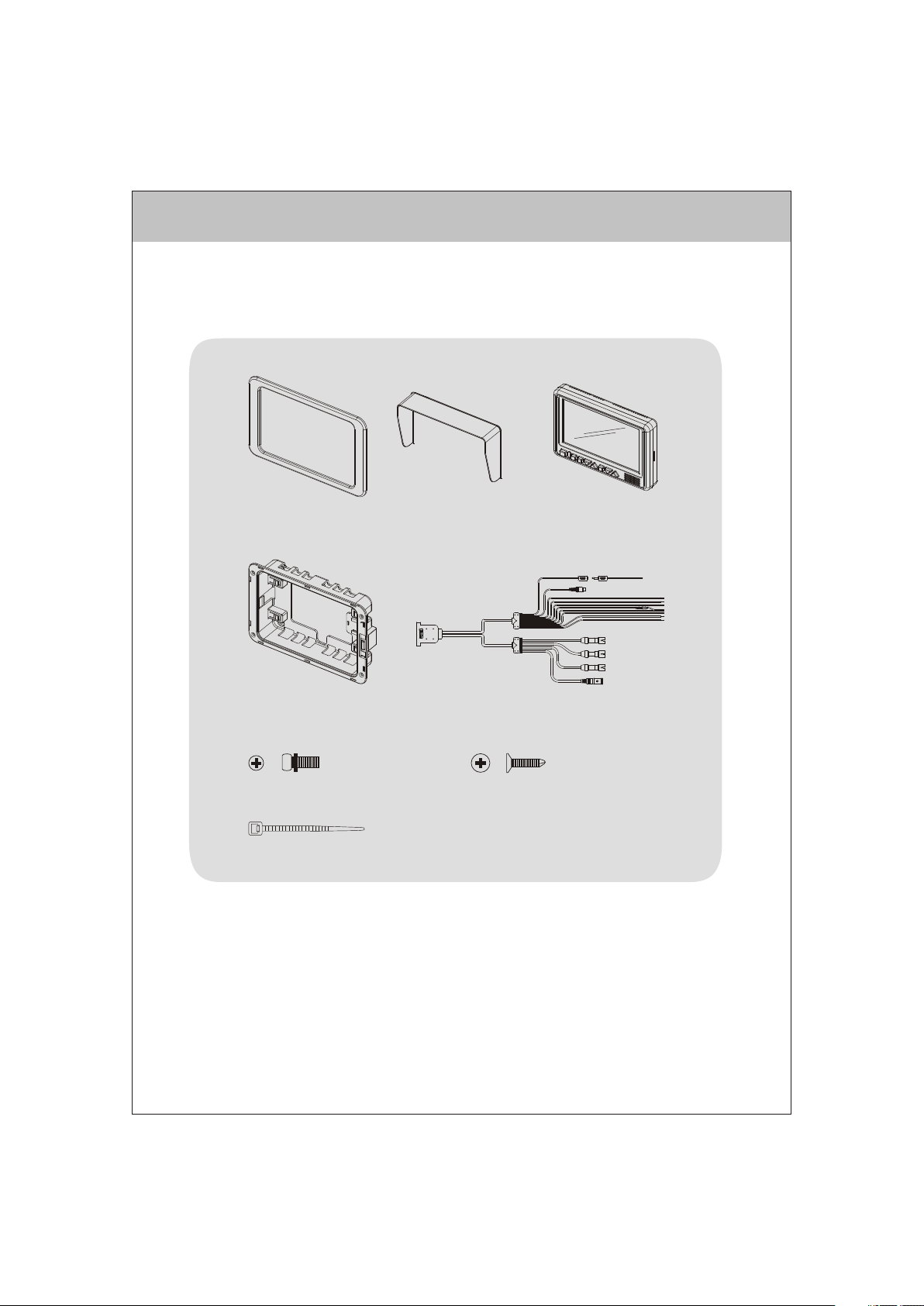
PACKING CONTENTS
TRIM RING
QTY. 1
FLUSH MOUNT BRACKET
QTY. 1
P/H Machine Screw
M4X10mm
QTY. 4
SUN SHIELD
QTY. 1
4" BLACK WIRE TIE
QTY. 1
CABLE QTY. 1
LCD MONITOR
QTY. 1
Flat Head Tapping Screw
M4X12mm
QTY. 4
3
Page 4
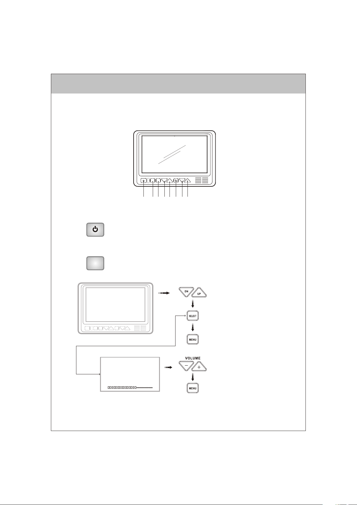
CONTROLS AND OPERATION
1. P OWER ON/O FF
-Press once to turn the unit on.
-Press again to turn the unit off.
-With power applied and the unit turned off, only the red power button is backlit.
-When unit is turned on, all buttons are backlit.
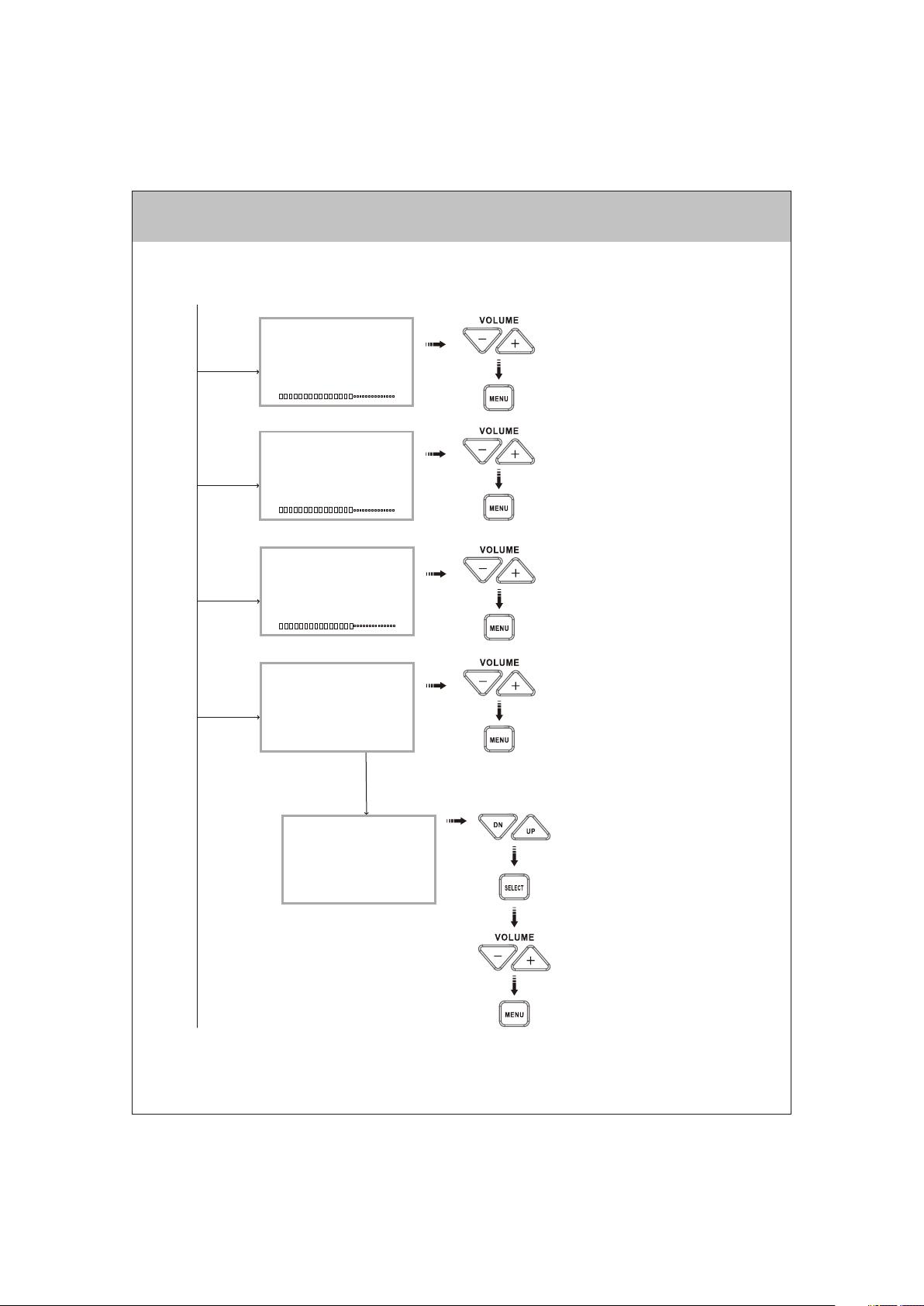
2. M EN U
-Press once to enter main menu mode (See Figure1).
MENU
-Press again before time out to exit the menu mode.
-Time out of OSD menu is approximately 8 seconds from when the last
key was pressed.
MAI N MENU
BRI GHTNE SS
CON TRAST
COLO R
TIN T
INP UT SETU P
AUT O-SC AN
SPL IT SCRE EN
DIS TANCE MA RKERS
ADVA NCED ME NU
Figur e. 1 Main menu
DN
MENU
SELECT
VOLUM E
UP
1 2 3 4 5 6 7 8
PRE SS TO NAVIG ATE U P/DOW N
PRE SS TO EXI T MAIN ME NU
PRE SS TO GO BA CK TO
MAI N MENU
SELECT
'BRIGHTNESS'
BR IGHT NESS
PRE SS TO ADJU ST +/-
PRE SS TO GO BA CK TO
MAI N MENU
4
Page 5
SELECT
'CONTRAST'
SELECT
'COLOR'
CO NTRA ST
CO LOR
PRE SS TO ADJU ST +/-
PRE SS TO GO BA CK TO
MAI N MENU
PRE SS TO ADJU ST +/-
PRE SS TO GO BA CK TO
MAI N MENU
SELECT
"TINT"
SELECT
"INPUT SETUP"
TI NT
INPUT SETUP
CH1: [ON(NORMAL) ; ON(MIRROR) ; OFF]
CH2: [ON(NORMAL) ; ON(MIRROR) ; OFF]
CH3: [ON(NORMAL) ; ON(MIRROR) ; OFF]
CH4: [ON(NORMAL) ; ON(MIRROR) ; OFF]
SOURCE NAME
SELECT
' 'SOURCE NAME
SOURCE NAME
CH1: _ _ _ _ _ _ _ _
CH2: _ _ _ _ _ _ _ _
CH3: _ _ _ _ _ _ _ _
CH4: _ _ _ _ _ _ _ _
PRE SS TO ADJU ST +/-
PRE SS TO GO BA CK TO
MAI N MENU
PRE SS TO ADJU ST +/-
PRE SS TO GO BA CK TO
MAI N MENU
PRE SS TO NAVIG ATE U P/DOW N
PRE SS TO SEL ECT CHA NNEL TO
REN AME
PRE SS TO MOV E TO NEXT L ETTE R
PRE SS TO SCR OLL THR OUGH
ALP HA-NU MERIC C HARAC TER SET
PRE SS TO GO BA CK TO
INP UT SETU P MENU
5
Page 6

SELECT
"AUTO - SCAN"
AUTO SCAN
SCAN: [OFF ; ON]
DELAY TIME: [1 sec. to 10 sec.]
PRE SS TO NAVIG ATE U P/DOW N
THR OUGH ME NU OPTI ONS
PRE SS TO TOGG LE THR OUGH O R
SEL ECT MEN U OPTI ON
PRE SS TO GO BA CK TO
MAI N MENU
SELECT
"SPLIT
SCREEN"
SPLIT SCREEN
2 - WAY
3 - WAY
4 - WAY
2-WAY SPLIT
3-WAY SPLIT
SELECT
"2-WAY"
SOURCE 1: [CH1 ; CH2 ; CH3 ; CH4]
SOURCE 2: [CH2 ; CH3 ; CH4 ; CH1]
AUDIO: [CH? ; CH? ; OFF]
SOURCE 1: [CH1 ; CH2 ; CH3 ; CH4]
SOURCE 2: [CH2 ; CH3 ; CH4 ; CH1]
SOURCE 3: [CH3 ; CH4 ; CH1 ; CH2]
AUDIO: [CH? ; CH? ; OFF]
PRE SS TO NAVIG ATE U P/DOW N
THR OUGH ME NU OPTI ONS
PRE SS TO TOGG LE THR OUGH O R
SEL ECT MEN U OPTI ON
PRE SS TO GO BA CK TO
MAI N MENU
PRE SS TO NAVIG ATE U P/DOW N
THR OUGH ME NU OPTI ONS
PRE SS TO TOGG LE THR OUGH O R
SEL ECT MEN U SETT ING
PRE SS TO GO BA CK TO
SPL IT SCRE EN MEN U
PRE SS TO NAVIG ATE U P/DOW N
THR OUGH ME NU OPTI ONS
PRE SS TO TOGG LE THR OUGH O R
SEL ECT OPT ION SE TTIN G
PRE SS TO GO BA CK TO
SPL IT SCRE EN MEN U
6
Page 7

4-WAY SPLIT
SOURCE 1: [CH1 ; CH2 ; CH3 ; CH4]
SOURCE 2: [CH2 ; CH3 ; CH4 ; CH1]
SOURCE 3: [CH3 ; CH4 ; CH1 ; CH2]
SOURCE 4: [CH4 ; CH1 ; CH2 ; CH3]
AUDIO: [CH1 ; CH2 ; ]CH4
PRE SS TO NAVIG ATE U P/DOW N
THR OUGH ME NU OPTI ONS
PRE SS TO TOGG LE THR OUGH O R
SEL ECT OPT ION SE TTIN G
PRE SS TO GO BA CK TO
SPL IT SCRE EN MEN U
SELECT
"DISTANCE
MARKERS"
SELECT
"ADVANCED
MENU"
DISTANCE MARKERS
MARKER OSD: [OFF ; CH1 TRIGGER]
ADVANCED MENU
TRIGGER PRIORITY : [CH1 ; CH2 ; CH3 ; CH4 ; SPLIT]
TRIGGER DELAY : [1 sec. to 10 sec]
PRESET
VIDEO FORMAT: [NTSC ; PAL]
OSD COLOR : [YELLOW ; WHITE ; MAGENTA]
CH4 SOURCE : [AV ; NAVIGATION]
CH. SEL. ON TRIGGER : [ON ; OFF]
SELECT
'PRESET'
PRESET
PRE SS TO TOGG LE THR OUGH O R
SEL ECT MEN U OPTI ON
PRE SS TO GO BA CK TO
MAI N MENU
PRE SS TO NAVIG ATE U P/DOW N
THR OUGH ME NU OPTI ONS
PRE SS TO TOGG LE THR OUGH O R
SEL ECT OPT ION SE TTIN G
PRE SS TO GO BA CK TO
MAI N MENU
PRE SS TO REC ALL BRI GHTN ESS,
CON TRAST, CO LOR AND TI NT
PRE SS TO GO BA CK TO
MAI N MENU
7
Page 8

3. S EL ECT
SELECT
Primary Function Input Source Select
-Pressing the SELECT button to sequence the source input modes
indicated in Figure 2.
as
-Source input modes that are skipped through the menu control
function will be skipped. (Figure 3 shows sequence with
CAM/INPUT 3 skipped.)
-Source ID is indicated by OSD in the top left corner of the screen.
-Source NAME is indicated by OSD in the bottom center of the screen.
Secondary Function Menu Option Selection
-While in Menu mode, the SELECT button is used to select the
highlighted function or option setting.
Third Function Scan Pause / Start
-While in source "SCAN" mode, pressing the select button will stop
the scan and display the current source. "Pause" will be displayed
by OSD.
Press SELECT again to resume source scan.
CH1 CH2 CH3 CH4
SPLIT(2-WAY)SPLIT(3-WAY)SPLIT(4-WAY)
Figure 2: Source Select Sequence
(All Source Options "On" )
CH1 CH2 CH4
SPLIT(2-WAY)SPLIT(3-WAY)SPLIT(4-WAY)
Figure 3: Source Select Sequence
(CH3 "Skip" )
8
Page 9

4. U P / DOWN
DN
UP
5. D ay / Night
6. Volu me +/-
Primary Function Camera Control
-Press the DN button to adjust the camera position downward.
-Press the UP button to adjusts the camera position upward.
Secondary Function Menu Navigation
-While in Menu modes, the UP and DN buttons are used to
navigate through available menu options.
Primary Function DAY/NIGHT Mode Setting
-Press the DAY/NIGHT button to sequence day/night backlight
compensation through "DAY", "NIGHT" and "AUTO" modes.
-Current mode setting is indicated by a temporary OSD located
at the bottom center of the screen.
Primary Function Speaker Volume Control
-Press the + button to increase the speaker volume.
-Press the - button to decrease the speaker volume.
Secondary Function Menu Option Setting Selection
-While in certain Menu modes ( Picture Adjustment, Source
Naming), the + and - buttons adjust settings or navigate through
available menu settings.
9
Page 10

Installation Instructions
BE FO RE YO U BE GIN INS TAL LAT ION:
Before drilling, be sure that no cable or wiring is on the other side. Clamp all wires securely
to reduce the possibility of them being damaged during installation and use.
Keep all cables away from hot or moving parts and electrically noisy components.
Wiring Definitions:
Power C onnectio n: Pin 1 C HANNEL 1 TRIGGER -Blue
Pin 2 Pin 3
Pin 4 POW ER IN DC (10 TO 32V) -Red
Pin 5 AUDIO/M UTE (AUDIO ON/OFF) -White
Pin 6
Pin 7 GRO UND -Black
Pin 8 2-WAY SPLIT TRIGGER - Yellow
Camer a 1 Input: 5-Pin C onnectio n for tilt cam era or camer a
exten sion cable
Camer a 2 Input:
Camer a 3 Input:
Camer a 4 Input:
LCD Pan el:
4-Pin C onnectio n for camera o r camera ext ension cab le
4-Pin C onnectio n for camera o r camera ext ension cab le
4-Pin C onnectio n for camera o r camera ext ension cab le
25-Pi n D-Sub Cabl e connecti on to monito r
CHANN EL 2 TRIGGER Br own
CHANN EL 3 TRIGGER -G reen
CHANN EL 4 TRIGGER -O range
Gener al:
1. Choo se the monit or and camer a location s.
2. Inst all all requ ired cable s in vehicle . A 3/4" (19mm) hole should be drilled for
passi ng camera ca bles throu gh vehicle w alls, barr iers, etc.
Insta ll split gro mmets wher e applicab le. If addition al cable pro tection is
requi red, insta ll convolu ted tubing o ver the cabl e.
3. After c able/wir ing has been r outed and co mponents a re in place, t emporari ly make all
syste m connecti ons and perf orm a system f unction ch eck. If the sy stem does no t
opera te properl y, see t he trouble shooting s ection.
4. Make s ure all cabl es are route d away from ho t or moving pa rts and away f rom
sharp e dges. Secu re cables wi th wire ties .
10
Page 11

Backup (Rear) Camera
Rear- mounted c ameras us ed for mon itoring w hile back ing up mus t be
conne cted to th e CA1 inpu t. Trigge r#1 must b e connect ed to the r everse ge ar light
circu it in the v ehicle.
There are two ca mera opti ons for re ar camera installa tions: st andard an d tilt.
Tilt c ameras an d cables w ill conne ct direct ly to the 5 -pin CA1 i nput. If a
stand ard(non- tilt) cam era is ins talled as the rear c amera, a 5 -pin to 4- pin adapt er
harne ss (inclu ded) must be used.
Side Camera
If sid e monitor ing camer as are ins talled, t hey shoul d be conne cted to ei ther CA2 o r
CA3 in puts. Tri ggers 2 an d 3 should be connec ted to the vehicle' s turn sig nal circu its.
Navigation
If a na vigation computer is instal led using the Compo nent inpu t, select the
Navig ation set ting from the Advan ced menu f or Source 4. Connec t the Red, Green,
Blue a nd Brown R CA connec tors from the AOM-7 694 to the Navigati on unit. A dapter
harne ss (11268 10) is req uir d to conv ert from t he 4-pin c amera con nector to RCA
conne ctors and must be co nnected t o Camera 4 input. Ue s the R d RCA connecto r
from t he harnes s to conne ct to the N avigatio n unit's a udio outp ut.
If a na vigation computer is instal led using the Compo site inpu t, select the A/V
setti ng from th e Advance d menu for Source 4. Adapter h arness (11268 10) is req uired
to con vert from the 4-pin camera co nnector t o RCA conn ectors. U se the Yel low RCA
conne ctor to th e Navigat ion unit' s composi te Video outp ut and the Red RCA
conne ctor to co nnect to t he Naviga tion unit 's audio o utput.
e
e
Note: If connecting a Camera to the Camera 4 input, the Advanced Menu setting for
Source A/V 4 must be set to A/V.
A remote c ontrol rep eater conn ection (1/ 8 jack) is inc luded to all ow control o f the
navig ation comp uter throu gh the senso r on the front o f the AOM-7694 monitor.
External (Additional) Monitors
An RCA vid eo output is i ncluded an d intended f or connect ion to an exte rnal monit or
(i.e. bedroom TV).
Channel Selection On Trigger
The nor mal (defau lt) operat ion is "OFF" . To turn this feature on go to the Advanced
Menu an d select "ON ". When "OFF ", the Camer a selectio n button wil l not functi on
when a tr igger wire i s active. Wh en "ON", the user c an manuall y override
the tri ggered cam era by using t he Camera se lection bu tton.
11
Page 12

Typical System
Connection
AO M- 76 94
MO NI TO R
A
- OPTION -
For s tan dard
ASA 4 pi n
camera
in CH ANN EL 1
CH AN NE L1
5- PI N FE MA LE C ON NE CT OR
(S -V ID EO T YP E)
CH AN NE L2 ~4
4- PI N AS A FE MA LE
CA ME RA C ON NE CT OR
(3 -V ID EO T YP E)
31 10 00 14 C AB LE
FEMALE
MALE
VIDEO OUT
RED GRN BLU BRO
DE TAI L-A
CA MER A4
RE D : R Sig nal I npu t
GR EEN : G Sig nal I npu t
BL UE : B Si gna l Inp ut
BR OWN : H ,V Sy nc Si gna l
MO LD -O VE R
ST RA IN R EL IE F
YE LL OW F EM AL E
RC A CO NN EC TO R
(V ID EO O UT )
1/ 8" S TE RE O JA CK
(3 -W IR E)
(IR COMMAND REPEAT)
TO N AV IG AT IO N
1
2 34567 8
BLUE
BROWN CHANNEL 2 TRIGGER
GREEN CHANNEL 3 TRIGGER
RED
WHITE
ORANGE CHANNEL 4 TRIGGER
BLACK GROUND
YELLOW 2-WAY SPLIT TRIGGER
CHANNEL 1 TRIGGER
POWER IN DC (10 TO 32V)
AUDIO/MUTE (AUDIO ON/OFF)
12
Page 13

PRODUCT SPECIFICATIONS
LC D PAN EL SPEC IF ICATIO NS
Size/Type
Brightness
Contrast Ratio
View Angles
(@ CR≥1 0)
Response Ti me
Backlight Type
Backlight Life
Operatio n Temperature Ran ge : -2 0℃ ~ +6 5℃
Storage Temperature Range : - 40℃ ~ + 80℃
Max Humidi ty : 85 %
Operatio n Voltage Range : DC 10V ~ 32V
Current Dr aw (t ypi cal ) : Max 3 0W
Signal sys tem : N TSC o r PAL (se lec tab le)
Video Aspect Rat io : 16 : 9
7" (DIAGONA L) TFT LCD
500 cd/㎡ (typ )
300 (typ)
Top (12 o'clock )
Bottom (6 o'c loc k)
Horizonta l
Rise : 12 ms (typ )
Fall : 18 ms (typ )
CCFL
10,000 hrs (mi n)
40° (min)
60° (min)
±6 0° (mi n)
Input Level : 1Vp -p 75
Audio Input Leve l : Max 0 .2 W- 150
Product Weight :
Product Di men sio ns :
2.2 Ibs / 1Kg
Monitor Only Dimens ion s:
7.75 W X 5.25 H X 1.25D inche s
Flange Dimensions
9.25 W X 6.25 H X 2 D inches
Ω Ω
㎷ ㎷
13
Page 14

AUDIOVOX PECIALIZED APPLICATIONS, L.L.C.SAUDIOVOX PECIALIZED APPLICATIONS, L.L.C.S
www.asaelectronics.com
Pr int ed in Kore a Pr int ed in Kore a
 Loading...