

Page 1
OPEMTION mNUAL
®
Voyager
7" Monochrome Four Camera Observation Monitor
VOM-784CT
with adjustable tilt camera control
VOM-784CT Features:
Four Camera input
Adjustable tilt camera control
Brightness / Contrast / Volume Day-night
Adjustment Control
Audio output
Automatic Trigger Operation
(Standby-On, Camera Switching)
Illuminated Front Panel
Mirror / Normal selectable
Auto-trigger switching compatible with turn signals
Camera-Monitor Warnings!
1. Camera/monitor system aids in the use of, but does not replace vehicle
side/rear-view mirrors.
2. Objects in camera/monitor view are closer than they appear.
When backing up, proceed cautiously and be prepared to stop.
Auoiovox SpEctAUZH) Applications, ll.c.
www.asaelectronics.com
Page 2

VOM-78 4C T O PER ATI ONS MA NUA L
IMPORTANT:
The VOYAGER Observation System has been designed to provide years of trouble-free operation.
Please read this manual thoroughly. This manual contains instructions to ease installation of the camera and monitor.
The VOYAGER Observation System is a supplement to standard rearview mirror systems, and will provide additional
rearview vision when installed and maintained properly.
The VOYAGER Observation System is not intended in any way to be a substitute for careful, cautious, defensive driving or for
the consistent adherence to all applicable traffic laws and motor safety regulations. This product is not intended to be a
substitute for rearview mirrors or for any other motor vehicle or boat equipment mandated by laws.
FEATURES:
VOM-784CT Monochrome 7" Monitor
• Day / night switch
• Brightness and contrast controls
• Volume control.
• Power / stand-by switch
• Audio output
• Four camera inputs
• Auto-trigger switching compatible with turn signals
• Tilt up / down switch
CONTENTS OF VOM-784CT T Monochrome Monitor
1-7" monitor
1- Snap-on sun visor
1- Monitor bracket
1- Power harness with locking connector
1- Range markers
4- Thumb screws (M5 x 15) with plain washer & spring washers
4- Attachment screws with washers(M5 X 12)
VOM-784CT 1
Page 3

VOM-784CT OPERATIONS MANUAL
VEC-65 Cable
1 - 65ft cable with waterproof connector. (Not supplied)
VCT-655 Cable
1-65ft cable with waterproof connector for tilt camera. (Not supplied)
Documents:
1- Operations manual
BEFORE INSTALLATION:
1. This system operates from 10 volts DC to 32 volts DC , negative ground.
2. Please install this system according to the instructions in this manual.
3. DO NOT DISASSEMBLE THE CAMERA OR THE MONITOR.
4. Connect the system to a switched ignition power source. Connection to a non-switched battery
battery life.
** WARNING**
1. To prevent electrical shock, DO NOT OPEN THE MONITOR CASE. There are potentially lethal voltages inside the monitor,
there are no serviceable parts inside, if evidence of tampering is detected, the warranty will be considered void.
2. Keep monitor away from leaking water, rain, moisture etc. It is not waterproof. Any moisture inside the monitor could cause
extensive damage.
Disassembling the camera will compromise the waterproof seal and this voids the Warranty.
power source will reduce
2 Voyager
Page 4

VOM-78 4C T O PER ATI ONS MA NUA L
INSTALLATION INSTRUCTIONS
VOM-784CT MONITOR
1. Attach monitor inside vehicle in a location convenient to the driver (e.g. Center of dash, overhead or in dash).
Do not impede the operator's view of any vehicle controls or the view outside the vehicle.
2. Use a compression plate to attach the monitor bracket to the dash or overhead (See Fig.1).
3. Adjust mounting angle of the monitor to allow driver to easily view the screen from all seat position (See Fig.2).
4. If necessary, snap sun visor into groove on front face of monitor. Press all (4) sides of the visor to snap it into place.
VEC-65 & VCT-655 CABLE (Not supplied)
1. The camera-to-cable connection is waterproof. The cable-to-monitor connection is not waterproof.
Be sure to orient the cable properly. The cylindrical end attaches to the camera. The rectangular box end attaches to
the monitor.(See Fig.3)
2. Do not run the VEC-65 & VCT-655 cable over sharp edges. Do not kink the cable.
Keep the cable away from hot and rotating parts.
3. Place all excess cable in convoluted tubing.
4. Tie the cable securely.
MAINTENANCE:
Remove dust and dirt with a damp soft cloth. Heavier dirt should be removed with a damp soft cloth
and mild detergent. Do not use strong cleaning agents containing gasoline, thinner, benzene or
alcohol. These substances may damage the exterior surface of the monitor.
VOM-784CT 3
Page 5

VOM-78 4C T O PER ATI ONS MA NUA L
** CAUTION **
1. Before drilling, be sure no cable or wiring is on the other side. Be sure to drill a 3/4" diameter hole only.
2. Feed as much cable as possible into vehicle and clamp securely. This reduces the possibility of being hooked
during production.
3. Keep all cables away from HOT, ROTATING and ELECTRICALLY NOISY components.
4. To increase protection of cable, place all excess wire and extension cable in convoluted tubing.
5. Do not twist camera cable and do not cut camera pigtail or cable.
WIRING MONITOR
1. See wiring diagram for connections.(See Fig.3)
2. Wiring Monitor:
Insert extension cable into camera #1 position if four cameras are used , be sure to mark each extension cable
properly, plug second ,third and four cables into camera #2, #3 or #4 position.
Bundle excess cable together using a cable tie or vinyl tape. This will avoid possible damage to cable during
operation.(See Fig.3)
3. The red wire is connected to an ignition power source, the black wire
is connected to chassis ground, and the blue wire is connected to the rear gear position, the brown, green and orange
wires are connected to the direction signals.(See Fig.3)
4 Voyager
Page 6

VOM-78 4C T O PER ATI ONS MA NUA L
FUNCTIONS AND OPERATION
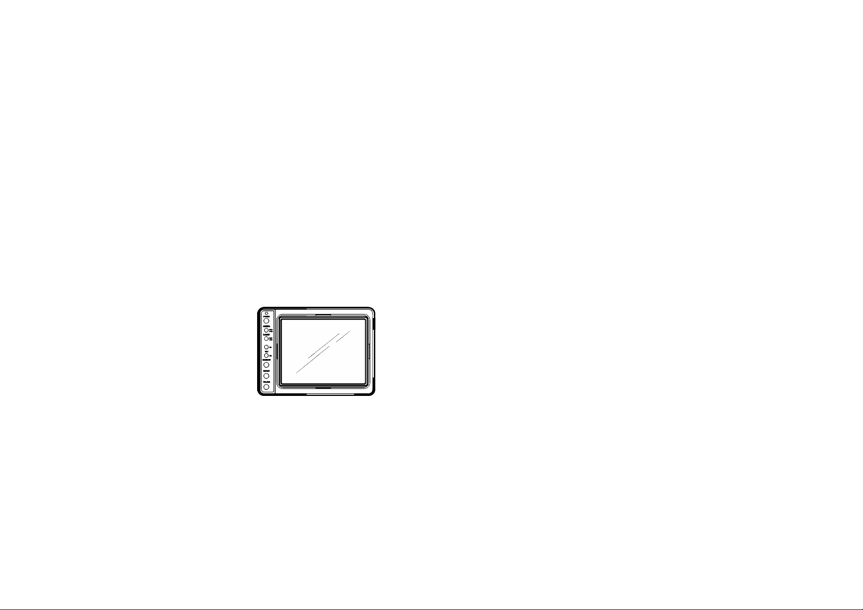
Front of Monitor : See FIGURE 4
1. Power switch
2. Camera selection
3. Day/ Night switch
4. UP switch
5. Down switch
6. Contrast
7. Brightness
8. Volume
FUNCTIONS AND OPERATION CONTINUED
Rear of monitor : See FIGURE 4
9. POWER CONNECTION :
(6) (J) (4)
d) (2) (l)
STAND- BY Monitor operates when vehicle transmission is switched into
"REVERSE" ON - monitor and system operate when ignition switch is "ON"
"CAT' used mainly for rear mounted camera or as specified by the installer.
"CA2", "CA3" & "CA4" and used mainly for side or mirror mounted camera or as specified by the installer.
Pre-set brightness and contrast levels optimized for day or night operation.
Adjustable tilt control to see upward image when use tilt camera.
Adjustable tilt control to see downward image when use tilt camera.
Variable control of contrast. Should be adjusted if the "DAY/ NIGHT"
switch does not achieve the most desirable picture.
Variable control of brightness. Should be adjusted if the "DAY/ NIGHT"
switch does not achieve the most desirable picture.
Variable control of internal speaker volume and output audio level.
Pin No.
Power ( DC lOV ~32V)
I
Trigger3 (DC 12V ~24V)
2
3 Ground
4 Trigger4 (DC 12V~ 24V)
Trigger I (DC 12V~24V)
5
Trigger2 (DC 12V~ 24V)
6
Description
VOM-784CT 5
Page 7

VOM-78 4C T O PER ATI ONS MA NUA L
10. MIR/NOR OPTION
Voyager camera switch
(magnet) in "MIR" position
- When the switch is in MIR ( ||) position, the picture will be reversed.
- When the switch is in NOR (|j) position, the picture will be normally displayed.
- Camera 2 & Camera 3 are operated individually.
11. AUDIO JACK
- Connects audio connector to an (option) external speaker.
12. CA1/CA2/CA3/CA4 INPUT JACK
- "CA1" used mainly for rear mounted camera or as specified by the installer.
- "CA2", "CA3" & "CA4" used mainly for side or mirror mounted camera or as specified by the installer.
6 Voyager
'Æ
Voyager Tilt camera
P" '
(VBC-130CT)
1
Page 8

VOM-78 4C T O PER ATI ONS MA NUA L
AFFIXING DISTANCE MARKERS TO THE MONITOR SCREEN
1. Clean monitor screen surface of fingerprints. Place distance indicators behind the vehicle at (3) feet, (6) feet and
(9) feet along the width of the vehicle.
These distances are measured from the rear bumper.(Refer to fig. 5)
2. Attach the markers to the monitor screen over the images of the distance indicators.
These markers represent distances of (3) feet, (6) feet and (9) feet from the back of the vehicle (See fig.5)
3. Affix the "STOP" marker on the monitor screen over the image of the rear bumper to locate the rear bumper.
4. The monitor screen is now "calibrated" for distances behind the vehicle of (3) feet, (6) feet and (9) feet.
DASH BOARD
OR OVERHEAD
STEEL PLATE FOR REINFORCEMENT
(RECOMMENDED FOR SECURE MOUNTING)
FIGURE 1
VOM-784CT 7
Page 9

VOM-78 4C T O PER ATI ONS M ANUA L
Unit : Inch MONITOR MOUNTING HOLE PATTERN
8 Voyager
FIGURE 2
Page 10

VOM-784CT OPERATIONS MANUAL
For Tilt Camera Installation in the CA1 Postion
TO MONITOR
CAMERA #1 INPUT
For Tilt Camera / Monitor Installation with existing VEC65 cable installed
WATERPROOF CAMERA CONNECTOR
GROMMET TO SEAL THOUGH
VEHICLE EXTERIOR
TO VOM-784CT
65 ft ^ '5
31100031
ADAPTOR CABLE
EXISTING VEC 65 CABLE
For Non Tilt Camera Installation in the CA1 Postion
TO MONITOR
CAMERA #1 INPUT
31100033
ADAPTOR CABLE GROMMET TO SEAL THOUGH VEHICLE EXTERIOR
=00 H3D=^=clliMin
WATERPROOF CAMERA CONNECTOR
65 ft
31100032
ADAPTOR CABLE
<u
note:
The audio line will
be used as the camera
tilt line resulting in
no Audio
VOM-784CT 9
Page 11

VOM-78 4C T O PER ATI ONS MA NUA L
REAR OF MONITOR
CONNECTIONS
RED(To Power
DC 10V-32V)
BLK (Ground)
TRIGGER 1
TRIGGER 2
TRIGGER 3
TRIGGER 4
Caution
Before making the connections, disconnect
the ground terminal of the car battery to avoid
short circuiting.
The plugs should be fully inserted into the
connectors or jacks. A loose connection may
cause the unit to malfunction.
10 Voyager
FIGURE 3
Page 12

VOM-78 4C T O PER ATI ONS MA NUA L
- MONITOR FRONT VIEW - MONITOR BACK VIEW -
MONITOR OPERATING CONTROLS AND CONNECTIONS
FIGURE 4
VOM-784CT 11
Page 13

VOM-78 4C T O PER ATI ONS MA NUA L
12 Voyager
(H) (ID
dZ)
dZ)
dZ)
(Tj)
WIDTH OF VEHICLE MARKERS EXAMPLE
FIGURE 5
dZ
ISTORI
1
ISTORI
© © ©
0 © ©
0 © ©
0 © ©
1
1
Page 14

VOM-78 4C T O PER ATI ONS MA NUA L
Operation Manual
SPECIFICATIONS:
System
VOM-784CT monitor
Rated voltage
Operating voltage
Current consumption 3.0 amperes (at 12vdc)
TV system
Picture tube Black and White
Picture image Factory preset to normal image
Picture resolution 600 TV lines
Power connector
Inputs 4-pin mini jack
Power requirements
Power consumption
12 volt DC, negative ground
10 to 32 volt DC
EIA
7 inch picture measured diagonally
90°degree deflection angle
• Red : Positive Power • Brown :
• Black : Ground • Green :
• Blue : Trigger 1 (12V ~ 24V) • Crange Trigger 4 (12V~ 24V)
1) Video input: 1,0V p-p Sync. Negative
2) 12V Tilt control power (CA1 only)
3) Audio input
4) 12V, 0.2A DC (output)
5) Shield Ground
10V to 32V DC
20W Maximum
Trigger 2 (12V ~ 24V)
Trigger 3 (12V ~ 24V)
VOM-784CT 13
Page 15

VOM-78 4C T O PER ATI ONS MA NUA L
Operating Temperature Range -15°C to + 50°C (+5°F to +122°F)
Storage Temperature Range -25°C to + 85°C (-13°F to +185"F)
Dimensions
Weight Approx. 2.5Kg/5 lbs
Accessories Supplied: A-
Power cable
DISCLAIMER: The use of the VOYAGER Observation system does not guarantee or promise that the user will not be in an
accident or otherwise not collide with an object.
The VOYAGER Observation system is not intended in any way to be a substitute for careful and cautious driving or for
the consistent adherence to all applicable traffic laws and motor safety regulations.
This product is not intended to be a substitute for rearview mirrors or for any other motor vehicle or boat equipment mandated
by law.
200(W) X 152(H) X 220(D) mm
7.9(W)X 6.0(H) X 8.7(D) Inch
Including projecting parts and controls
Including mounting bracket
Mounting bracket 1EA
NUT 4EA
Machine screws 4EA
Tapping screws 4EA
Spring washers 4EA
Flat washers (12X5) 4EA
Flat washers (20X5) 4EA
B- Cable bracket 1EA
Machine screws 3EA
c-
Handle screws 4EA
D- Sun visor 1EA
5 ft
* Design And Specifications Are Subject To Change Without Notice.
14 Voyager
Page 16

 Loading...