

Page 1
M-01335, Rev. A
The DBS-4500 / Land Version
In-Motion Satellite Television System
User’s Guide
Includes:
– 100 Series Antennas
IMPORTANT!
DO NOT OPERATE THIS SYSTEM
WITHOUT FIRST READING
SECTIONS 3 & 7 OF THIS MANUAL.
All rights reserved, patent pending
Copyright ? 1999 by Datron/Transco Inc.
A subsidiary of Datron Systems Incorporated
Page 2

M-01335, Rev. A
NOTICE!!
Important Warranty Information
Keep this User Guide with the Antenna
System at all times.
For Customer Service, contact an Authorized Service Center
nearest you, or call Datron at 1-(800)-287-5052.
Page 3

M01335, Rev. A
Page 1
TABLE OF CONTENTS
1. INTRODUCTION............................................................................................................ 2
1.1 What to Expect While Operating the DBS-4500..................................................2
1.2 Features of your DBS-4500.................................................................................2
2. SYSTEM OVERVIEW .................................................................................................... 3
2.1 Antenna/Radome Assembly................................................................................3
2.2 Antenna Control Unit (ACU) ................................................................................3
2.3 Satellite Receiver.................................................................................................3
3. SYSTEM OPERATION................................................................................................... 5
3.1 General................................................................................................................5
3.2 Powering On the System.....................................................................................5
3.3 First Time Start-Up ..............................................................................................5
3.4 Automatic Satellite Signal Acquisition and Tracking............................................6
3.5 Power Conservation Mode ..................................................................................6
3.6 Operating Tips.....................................................................................................6
4. REGULAR SERVICE AND PREVENTIVE MAINTENANCE........................................... 8
5. SPECIFICATIONS.......................................................................................................... 8
5.1 Mechanical ..........................................................................................................8
5.2 Electrical..............................................................................................................8
6. TROUBLESHOOTING................................................................................................... 9
6.1 Failure Messages ..............................................................................................11
7. PRECAUTIONS ........................................................................................................... 11
8. GLOSSARY................................................................................................................. 12
9. WARRANTY................................................................................................................. 13
APPENDIX A – DATRON SATELLITE SYSTEM RECEIVER COMPATABILITY MATRIX
Page 4

M-01335, Rev. A
Page 2
1. Introduction
Thank you for purchasing CruiseTV?, Datron’s DBS-4500 Land In-Motion Satellite Television
System. You now own one of the most advanced automatic satellite systems available, providing
access of more then 200 channels of digital television and CD quality audio programming while your
vehicle is in motion. The DBS-4500 is specially designed for Direct Broadcast Satellite (DBS)
television viewing while traveling on highways and thoroughfares in the lower 48 states that have a
clear view to the southern sky.
1.1 What to Expect While Operating the DBS-4500
The DBS-4500 has been designed as an open road, cross-country system that works best on open
stretches of road. It has not been designed to drive around town, but may surprise you with its intown capabilities. As you drive your DBS-4500 you will learn its characteristics and how it works
best for you. If you encounter any conditions that you don’t expect, just contact us at 1-800-2875052 and we will discuss them with you.
1.2 Features of your DBS-4500
? Automatic signal acquisition from anywhere in the Continental United States on roads with an
unobstructed view to the DBS satellite in the southern sky.
? Automatic satellite tracking and TV viewing while your vehicle is in motion
? Dual LNBF allowing two receivers to be used simultaneously
? Automatic system calibration
? On-screen status reporting
? Compatibility with most digital satellite system receivers equipped with a low speed data port
? Power conservation mode when vehicle is parked
This User’s Guide describes the operation and use of the DBS-4500 satellite system. Operation of
your satellite receiver is covered in your receiver’s operating instructions.
Please take the time to read this booklet completely. Your new CruiseTV? system by Datron
represents the very latest in satellite tracking technology. Therefore it is very important that you
understand the proper operation of both your receiver and your satellite antenna system.
Page 5

M-01335, Rev. A
Page 3
2. System Overview
Your Datron DBS-4500 is the first fully automatic in-motion satellite system specifically designed for
use with the new high-power DBS television satellites. The satellites have revolutionized television in
the United States and have made DBS television receiving systems the fastest selling consumer
electronics product in history.
The DBS-4500 has been designed for simplicity of operation. The DBS-4500 incorporates the latest
solid state satellite tracking technology with advanced computer software to give you, our customer,
true value and years of entertainment enjoyment.
Datron has been designing and manufacturing satellite tracking systems for military and commercial
customers worldwide since 1969. This experience has created this revolutionary new satellite
television receiving system.
The DBS-4500 has three main parts, the Antenna/Radome Assembly, the ACU, and the Satellite
Receiver. Since your DBS-4500 was probably installed by a Datron dealer, we will give you some
background on the system.
2.1 Antenna/Radome Assembly
The DBS-4500 uses a specially designed 12” x 24” parabolic reflector (dish) and an LNBF to receive
the DBS satellite’s signals. The antenna and its drive motors are covered by a low-profile protective
cover called a radome. The dish is automatically and continuously pointed at the satellite by the
antenna control unit (ACU) while the vehicle rolls down the road. The radome is specially designed
and molded from a material that is strong and light weight and must not be painted with metallic based
paints. The metallic content of many paints will severely impair system performance.
2.2 Antenna Control Unit (ACU)
The ACU is located under the radome. The ACU contains the motion sensing devices that give the
ACU’s computer the information it needs to keep the antenna accurately pointed at the satellite as the
vehicle turns, sways and rolls over bumps. Your only interface with the ACU is “ON” or “OFF”
through the remote switch in your vehicle.
2.3 Satellite Receiver
The final main part of the system, other than your TV, is the satellite receiver. The receiver is the
same type of unit you would use to view DBS television in your home. Appendix A contains a matrix
of compatible receivers.
Page 6
M-01335, Rev. A
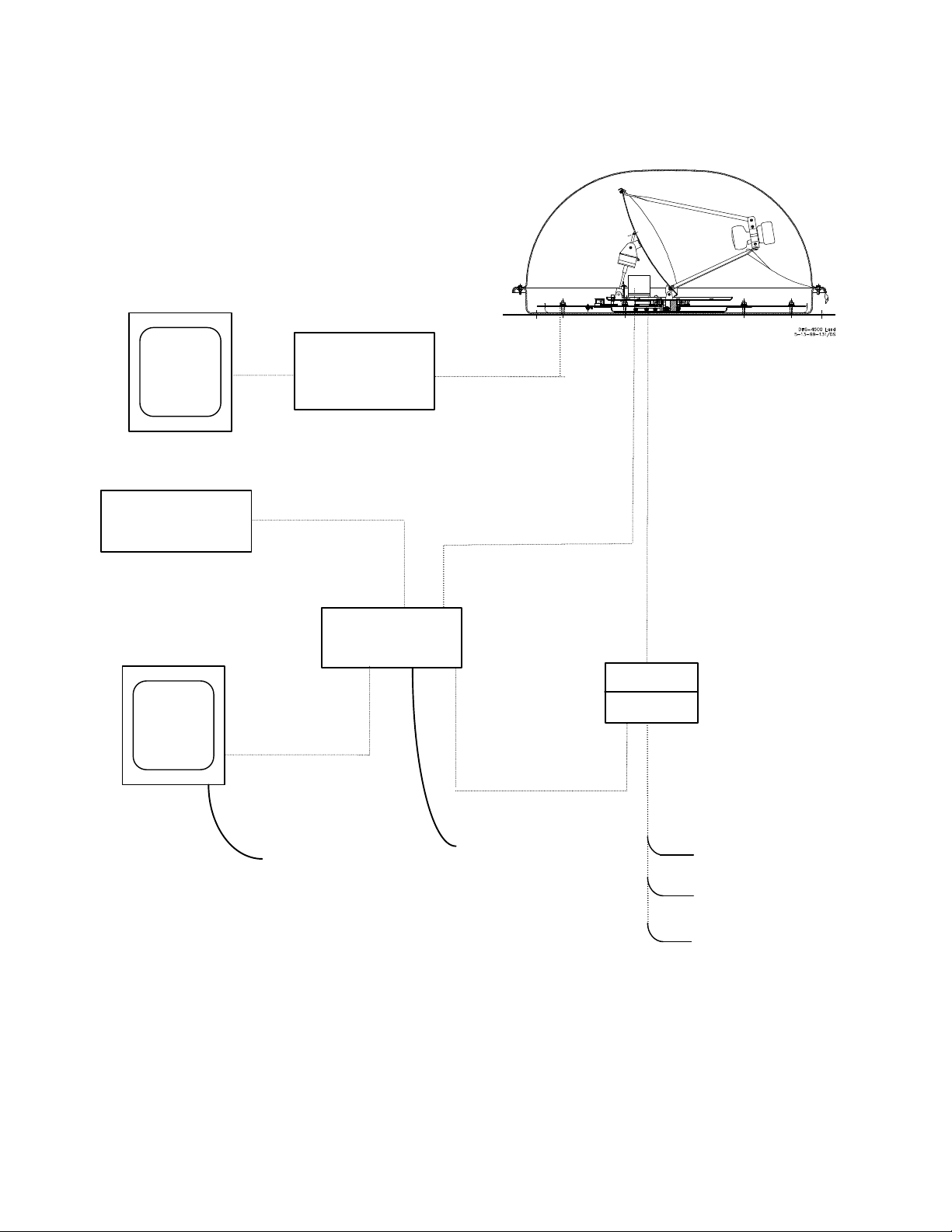
TV
Page 4
2nd
TV
2nd
Satellite
Receiver
? Coax Cable
ANTENNA
Stereo
Optional
Audio Connection
Satellite
Receiver
Video Connection
110 VAC OR 12 VDC
? Coax Cable
Receiver Control
110 VAC
?
Antenna Control Cable
Receiver
Control Interconnect
Power Switch
GND
+12 VDC
Figure 1. Diagram of DBS-4500 System Connections
Page 7

M-01335, Rev. A
Page 5
3. System Operation
This section describes the operation of the DBS-4500 satellite system. It does not focus on the
operation of the receiver, except where it pertains directly to the operation of the DBS-4500 satellite
system. For questions about your satellite receiver, refer to the receiver’s operating instructions.
3.1 General
The satellite system must have an unobstructed view of the southern sky. Mountains, buildings,
overpasses, dense trees and other objects can block the satellite’s signal from reaching the antenna and
will result in signal dropouts. If the signal is blocked, the antenna will continue to track the satellite at
its last known position. Re-acquisition should occur within seconds in most cases. If blockage is
sustained for long periods of time (e.g., going through a tunnel) re-acquisition may take several
minutes. For situations where there is blockage or loss of satellite signal for five (5) minutes or more,
the system power should be shut down, the blockage cleared, and the system restarted. This will reboot the system, and restart the initialization process. Satellite acquisition should occur within two (2)
minutes. Sharp turns of the vehicle at accelerated speeds may also cause the antenna to briefly lose the
satellite signal. This is normal operation.
3.2 Powering On the System
To apply power to the system, toggle the power switch to the ON position. The on-screen status
message should read “INIT-REV XXXX”. If the status message is not displayed on the television set,
turn off the power and check to see that cable and power connections are properly engaged and
secure. It is recommended that when first acquiring the signal, as indicated by the “INIT-REV
XXXX” message, that your vehicle remain stationary. Drop-outs for the first few minutes may occur
if the vehicle is in motion while the system is initialized.
To turn off power, return the power switch to the OFF position.
3.3 First Time Start Up
The first time the DBS-4500 is turned on after installation it may take several minutes for the unit to
acquire the satellite. This initialization feature determines where you are geographically with respect
to the satellite. Once the system is initialized, the unit will remember where you are and continually
update your position as you move. Future start-ups will use this information to minimize acquisition
time.
Page 8

M-01335, Rev. A
Page 6
If the vehicle is moved great distances (approximately 100 miles), with the DBS-4500 turned off, a
new location finder mode will be automatically entered and the initialization may take a little longer
than normal. This new location will then be stored for all future start-ups.
3.4 Automatic Satellite Signal Acquisition and Tracking
Satellite signal acquisition and tracking is fully automatic. No action on your part is necessary. It is
recommended that the initial signal acquisition of the satellite be done when the vehicle is not moving.
Acquisition will occur in less than two (2) minutes.
The rest of this section describes what to expect during the acquisition and tracking process.
Immediately after the system is turned on the message “INIT-REV XXXX” will appear during which
time the vehicle should be kept stationary. “Searching for satellite signal” will appear after “INITREV XXXX” is complete.
When a signal has been located, your receiver will begin displaying the programming for the selected
channel and the DBS-4500 will automatically begin tracking the satellite.
During the tracking process, you may experience a momentary loss of picture. This behavior is
normal. Your picture will return within a few seconds.
3.5 Power Conservation Mode
If the vehicle has remained stationary for approximately five (5) minutes with the unit on, it will
automatically enter a reduced power mode and the antenna will stop moving. Once the vehicle is
placed in motion the unit will automatically revert back to its tracking mode.
You may also turn power off and continue to watch television if the vehicle is stationary. The unit will
re-initialize when power is reapplied. With the power turned off, the antenna may eventually lose the
satellite signal and re-initializing will be required.
3.6 Operating Tips
? To minimize signal dropouts in the first few minutes of use it is best to allow the DBS-4500 to
warm up for five (5) minutes before placing the vehicle in motion.
? The antenna may be started while the vehicle is in motion. However, the vehicle should be moving
in a straight path for best results. Allow approximately three (3) minutes to locate the signal while
the vehicle is in motion. You may acquire the signal while traveling up or down a grade as long as
the vehicle is moving in a straight path.
Page 9

M-01335, Rev. A
Page 7
? When stopping in an area where the antenna will be blocked from the satellite (i.e., gas stations,
parking structures, heavy foliage, etc.) it is recommended the antenna be turned off and restarted
when the antenna’s line of sight to the satellite is clear.
? When the vehicle is stationary for long periods of time, turn antenna system off after acquiring
signal. Turning system off will reduce power drain and extend operating life of antenna and vehicle
battery.
? If the antenna loses track for approximately two (2) minutes, it will automatically re-initialize, as
indicated by the “INT-REV XXXX” message. The vehicle should be kept in a straight path during
this re-initializing mode.
? If there is excessive vehicle motion during the initializing process, the system will remain in the
initializing mode until motion has reduced to an acceptable level, or until five (5) minutes has
elapsed.
? If the antenna loses track for five (5) minutes or more switch the power off and on again to reboot
the system.
? The antenna can move 360° from the center position in either direction. The word “repositioning”
will appear when the antenna unwraps the wiring bundle. When the antenna repositioning is
complete, the system will start tracking the satellite again. This process will take approximately
five (5) seconds.
? Sharp turns or curves at high acceleration may result in brief signal loss. This is normal operation.
Signal should reappear in a few seconds.
? Do not attempt to remove the radome (cover). Contact with the internal components may cause
serious damage to the unit and void any warranties.
? Clean the outside radome surface of bugs, debris and other contamination with water and a mild
detergent periodically.
? In heavy dew conditions operation can be optimized by wiping the excess moisture from the
radome or just spraying the unit off with a water hose. The vehicle may be driven to blow the
moisture from the radome. The antenna radome may be treated with rain repellent to minimize
moisture buildup.
Page 10

M-01335, Rev. A
Page 8
4. Regular Service and Preventive Maintenance
CruiseTV? has been designed for trouble-free operation. You can enhance the life of your equipment
by having an authorized Datron dealer inspect and service your antenna system once a year. To locate
the authorized dealer nearest you, contact Datron/Transco Inc. at 1-800-287-5052.
5. Specifications
5.1 Mechanical
Antenna (Elliptical) ..........................................................................................12” X 24”
Operating Temperature ........................................................................................0ºF - 125ºF
Operating Wind Level ........................................................................................... No Limit
Radome Height ................................................................................................. 15.0”
Radome Diameter ................................................................................................. 33.0”
Antenna Movement ....................................................22º to 66º Elevation, 720º Azimuth
Weight on Roof ................................................................................................35 lbs.
Mounting Footprint .......................................................................................34.5” Circle
5.2 Electrical
Operating Voltage .............................................................................. 12VDC Nominal
Operating Current .....................................................................2.0 Amps DC Nominal
.................................................................. 3.0 Amps DC Maximum
Page 11

M-01335, Rev. A
Page 9
6. Troubleshooting
Error conditions are described in Table 1 and possible solutions are indicated for each symptom. If
you have trouble and cannot resolve it with this guide, contact your Datron dealer or Datron/Transco
Inc. at 1-800-287-5052.
Table 1. Error Conditions and Solutions
Symptom Indication Cause Possible Solution
Does not
acquire
“INIT-REV XXXX”
“INIT-REV XXXX”
“Searching for
No screen display
does not display on
monitor
continuously
displayed on monitor
Satellite”
continuously
displayed on monitor
? Switch not turned on
? Battery dead
? Power not
connected to battery
? Antenna not
connected
? Bad switch
? Monitor not turned
on
? Receiver not turned
on
? ACU not connected
? Receiver not
connected
? Excessive motion ? Normal operation;
? View is obstructed
? Antenna coax not
connected
? Radome covered
with debris
? Initialized during
excessive motion
? Radome covered
with dew
? Turn on switch
? Recharge/replace
battery
? Connect power to
battery
? Connect missing/loose
cable
? Replace switch
? Turn on/plug in monitor
? Turn on/plug in receiver
? Connect missing/loose
cable
? Connect missing/loose
cable
reduce vehicle motion
? Move vehicle to new
location
? Connect all cables
? Clean radome
? Stop motion during
initialization
? Spray radome with hose,
or wipe excess moisture
from radome, or drive
vehicle to remove
moisture coating
Page 12

M-01335, Rev. A
Page 10
Table 1. Error Conditions and Solutions
Symptom Indication Cause Possible Solution
Picture drops
out
Continuous freeze
Picture pixeling
“Searching for
“Repositioning”
“INIT-REV XXXX”
“Cal. Required”
NVROM INITZD
Momentary freeze
frame
frame
satellite” displayed
on monitor
displayed on monitor
displayed
displayed on monitor
? View obstructed
? Large vehicular
motion
? Receiver
malfunction
? View obstructed
? Large vehicular
motion
? Long time view
obstruction or
? Very large vehicular
motion
? Vehicle turned past
limits
? Re-acquisition not
successful
? Displays when
calibration reset
required
? System reset to
factory defaults
? Normal operation
? Turn receiver off and on
? Normal operation
? Normal operation;
picture should return
within three minutes
? Reboot system
? Normal operation;
picture should return
within 30 seconds
? Normal operation;
picture should return
within three (3) minutes
? Calibration performed by
turning power off and on
every ten seconds, five
times
? Normal operation during
reset calibration
Page 13

M-01335, Rev. A
Page 11
6.1 Failure Messages
Failure messages are described in Table 2. If any of these messages are displayed, contact your
nearest Authorized Service Center or call Datron directly at (800) 287-5052.
Table 2. Failure Messages
Failure Messages Displayed
on Screen
CODE: 01 AZ & EL Both AZ and EL index
CODE: 02 AZIDX AZ index switch/motor failed.
CODE: 03 ELIDX EL index switch/motor failed.
CODE: 04 A2D Fault in the analog-to-digital
CODE: 05 XRATE X gyro rate sensor failed.
CODE: 06 YRATE Y gyro rate sensor failed.
CODE: 07 ZRATE Z gyro rate sensor failed.
CODE: 08 PLEVL Pitch level sensor failed.
CODE: 09 RLEVL Roll level sensor failed.
CODE: 10 LNBFV Failure of the R-hand/L-hand
Reason for Message Display Possible Solution
switches/motors failed.
converter.
polarity of the LNBF.
Contact nearest Authorized
Service Center or call Datron
at (800) 287-5052
? Repair or replace coax
? Check receiver voltage to
LNBF
7. Precautions
? Do not open or remove any part of the antenna control unit or the antenna/radome assembly.
There are no user serviceable parts inside.
? Operate the antenna system on a clean, continuous 12 VDC supply only. Fluctuations in voltage
can degrade performance. OBSERVE PROPER POLARITY ON THE POWER
CONNECTION.
? To locate the authorized dealer nearest you, f you are in need of assistance, contact Datron/Transco
Inc. Customer Service Department at 1-800-287-5052.
? Turn antenna system OFF after acquiring signal if vehicle is to be stationary for a long time. Power
off will reduce power drain and extend operating life of antenna and vehicle battery.
Page 14

M-01335, Rev. A
Page 12
8. Glossary
The following is a glossary of terms used both within this User Guide and when talking about digital
satellite television systems and DIRECTV?.
Azimuth – refers to the azimuth axis, indicating the rotating movement of the antenna about an axis
perpendicular to the surface. Looking down on the antenna from above, the azimuth movement is
either clockwise or counterclockwise.
Azimuth Angle – the angle from true north or from the vehicle’s fore and aft center line, in a plane
parallel with the surface, to which the antenna is pointing. In general, the angle increases as the
antenna turns clockwise, as viewed from above.
Cable Wrap – a method of securing the cable, yet allowing the antenna to rotate freely. The DBS4500 has 720° of rotation. When the limit is reached the antenna will unwind.
DBS – Direct Broadcast Satellite. A special high power TV satellite that broadcasts to 18” dishes.
Satellite Receiver – an electronic device which decodes and processes the DBS data. Usually, this
data produces a viewable picture which can be displayed on a television set.
Elevation – usually refers to the elevation axis, indicating a rotating movement of the antenna about
an axis parallel to the surface.
Elevation Angle – the angle between the surface and the antenna’s pointing angle. The values can
range from 0º (parallel with the surface) to 90º (straight up in the sky) to 180º (parallel with the
surface again, but in the opposite direction from 0º.)
Page 15

M-01335, Rev. A
Page 13
9. Warranty
Datron/Transco Inc. (DTi) warrants this product to be free from defects in material and workmanship
for two (2) years’ parts and one (1) year labor. Proof of purchase in the form of a bill of sale or
invoice indicating the product installation date must be presented to obtain warranty service.
Datron/Transco Inc. liability hereunder is limited to cost of parts for two (2) years and labor costs for
one (1) year to replace or repair, at its discretion, any part or parts determined to be defective in
material or workmanship. Parts manufactured other than by Datron/Transco Inc. are warranted
separately by the applicable parts manufacturer.
This warranty does not cover cosmetic damage of a non-functional nature or damage due to acts of
God (including but not limited to lightning, windstorm, hail). This warranty also does not cover
damage caused by improper voltage regulation. This warranty does not apply if the product has been
improperly installed or subjected to misuse, neglect, or accidental damage.
This warranty is invalid if the factory-applied serial number has been altered or removed from the
product.
Repair or replacement as provided under this warranty is the exclusive remedy of the consumer.
Datron/Transco Inc. shall not be liable for any incidental or consequential damages for breach of any
expressed or implied warranty of this product. In no event will Datron/Transco Inc. liability, if any,
exceed the purchase price paid for the product. THERE ARE NO WARRANTIES EXPRESSED
OR IMPLIED EXCEPT AS STATED HEREIN.
To locate the authorized dealer nearest you, contact Datron/Transco Inc. Customer Service
Department at: 1-800-287-5052.
Page 16

M-01335, Rev. A
Appendix A
Datron Satellite System
Receiver Compatibility Matrix
Page 17

Receiver
DIRECTV/DISH Compatible
SONY
SAT-A50
OK - DIRECTV (6)
RCA
HNS
ECHOSTAR
All Others
Not Compatible
Datron Satellite System Receiver Compatibility Matrix
SAT-B1 Not Compatible
SAT-B2 Not Compatible
SAT-B3 OK - DIRECTV
SAT-A1 OK - DIRECTV
SAT-A2 OK - DIRECTV
SAT-A3 OK - DIRECTV
SAT-A4 OK - DIRECTV
DRD122RW Not Compatible
DRD102RW Not Compatible
DRD203RW Not Compatible
DRD303RA Not Compatible
DRD403RA OK - DIRECTV (5)
DRD703RA OK - DIRECTV (5)
DRD505RB OK - DIRECTV (5)
DRD523RB OK - DIRECTV (5)
DRD515RB OK - DIRECTV (5)
DRD203RB OK - DIRECTV (5)
M-01335, Rev. A
July 2, 1999
Page 1 of 2
HIRD-A33 OK - DIRECTV (5)
ISD2350 OK - DISH (4)
ISD4000 OK - DISH (4)
ISD5000 OK - DISH (4)
ISD3350 OK - DISH (4)
ISD4500 OK - DISH (4)
Page 18

NOTES:
3
4
5
FOR OPTIMUM PERFORMANCE OF THE DBS-4000 AND DBS-4500 "CRUISETV" IT IS SUGGESTED THAT THE SONY
SAT-A1, SAT-A2, SAT-A3 or SAT-A4 RECEIVERS BE USED.
6
Compatible with software revision D or above.
ADDITIONAL
NOTES:
Datron Satellite System Receiver Compatibility Matrix
HNS Receivers: Requires special ACU/Satellite Receiver Interface Cable - Datron Part Number: 128649-006
ECHOSTAR Receivers: Reference Technical Bulletin #11
Echostar Receivers requires special interface cable:
DBS-4500-100 Datron Part Number: 130742-101
M-01335, Rev. A
July 2, 1999
Page 2 of 2
No models of the Uniden receivers are compatible with Datron products.
Hitachi and Toshiba receiver compatibility pending
Call Datron Datron Technical Support 1-800-287-5052 if you have questions regarding this data.
 Loading...