

Page 1
Arzel R Zoning Technology, Inc.
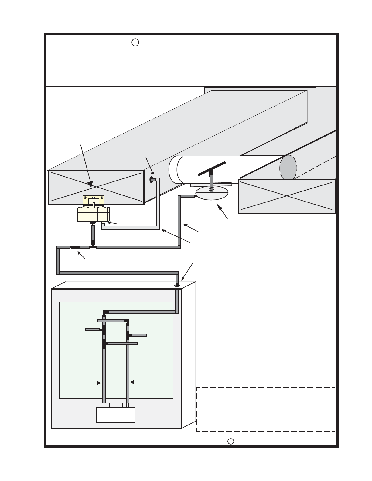
Modulating Bypass Control
Adjustable from .05” to .5” wc Static Pressure
Locate Pressure Transmitter within
24” of Bypass Damper.
Mount in Verticle position
Static Press Transmitter
Pitot Tube (3/16”OD)
“Low” port
Fixed Restrictor (.012”)
Bypass Duct
3/8” OD Static Press Sensing Tube (clear)
1/4” Bulkhead Port
Supply Duct
Return Duct
Spring Open Bypass Damper
1/4” OD PVC Air Tube (black w/color stripe)
Operating Sequence of the Arzel
Modulating Bypass Control;
Bypass
Arzel Zoning Panel- 200 mps/AirBoss
Bypass Pressure line
Zone # 1
Press/Vac Lines
Pressure Line
Vacuum Line
Pump
When static pressure in the duct is within the
normal range (.05 to .10), the static pressure transmitter
allows pressure to increase in the Bypass actuator and
closes the Bypass damper.
When the static pressure increases above the
the preset level, the Static Pressure Transmitter reduces
the pressure allowing the actuators internal spring to
open the bypass damper until the maximum allowable
static is reached.
The Modulating Bypass control can maintain
a desired maximum static pressure by holding the
bypass damper position anywhere between 0 and
100%.
Page # 1 - Modulating Bypass Operation
Page # 2 - Field Retro-fit Installation instructions
Page # 3 - Field Up-grade from Press Switch Control
Page # 4 - Installation of Factory Installed Modulating
Bypass control.
C
Copyright 2002 Arzel Zoning Technology, Inc.
Arzel® Zoning Technology, Inc.
Page 2
R
Arzel Zoning Technology, Inc.
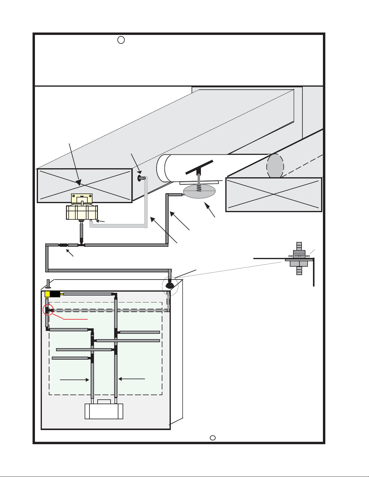
Modulating Bypass Control
Field Retro-Fit Installation Instructions
Locate Pressure Transmitter within
18” of Bypass Damper.
Mount in Verticle position
Static Press Transmitter
Pitot Tube (3/16”OD)
Supply Duct
Bypass Duct
Return Duct
Fixed Restrictor (.012”)
zone #1
Add Tee
Zone #1 Press
Zone #3 Vac
Zone #3 Press
Pressure Line
“Low” port
Bypass Press line
Zone #2 Vac
Zone #2 Press
Vacuum Line
Spring Open Bypass Damper
1/4” OD PVC Air Tube (black w/color stripe)
3/8” OD Static Press Sensing Tube (clear)
1/4” Bulkhead Port
Retro-Fit Installation Process
1 Install the bypass duct and “Spring Open” Bypass damper.
Bypass duct should enter return duct as far from equipment
as possible, prior to first reducer or take off. Bypass damper
should be located on the supply end of the bypass duct.
2 Mount the Pressure Transmitter on the supply duct within
24” of the Bypass damper.
3 In the panel, insert bulkhaed fitting into blank opening
(see illustration), cut a tee into the pressure line (left side
of pump) and connect with tube. Connect an air line from the
bulkead (top) to the Restrictor on the Pressure Transmitter
tee. (black w/ red cap).
4 Insert the Pressure sensing tube into the supply duct (5/16”
hole) between the equipment and the bypass duct.
Nut
Pump
Arzel Zoning Panel- 200 mps/AirBoss
Arzel® Zoning Technology, Inc.
5 Connect the damper tubing to the Pressure Transmitter Tee,
opposite of the restrictor (remove red cap).
6 With only the smallest zone calling for cooling, adjust the
C
Copyright 2002 Arzel Zoning Technology, Inc.
Page 3
R
Arzel Zoning Technology, Inc.
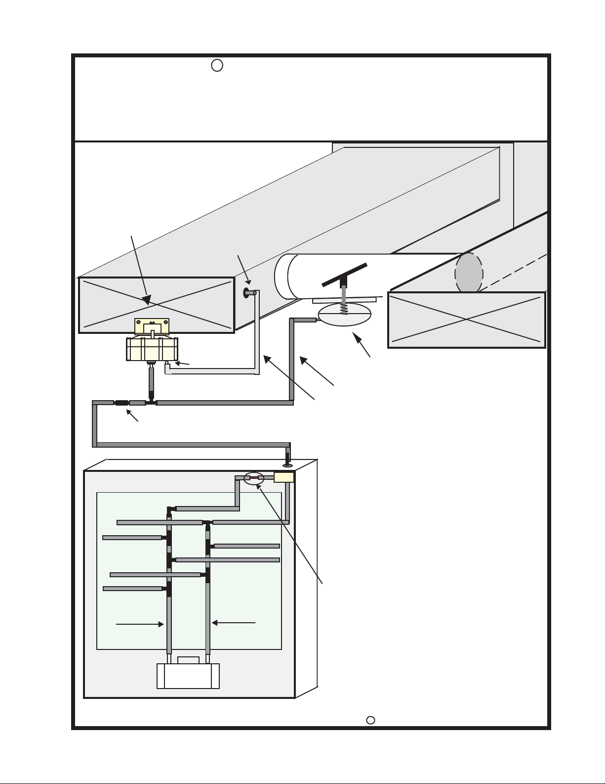
Modulating Bypass Control
Field Upgrade from the “Pressure Switch” Bypass Control
Locate Pressure Transmitter within
24” of Bypass Damper.
Mount in Verticle position
Static Press Transmitter
Pitot Tube (3/16”OD)
Supply Duct
Bypass Duct
Return Duct
Fixed Restrictor (.012”)
Arzel Zoning Panel
Bypass Pressure line
Zone #1 Vac
Zone #1 Press
Zone #3 Vac
Zone #3 Press
Pressure Line
“Low” port
Zone #2 Vac
Zone #2 Press
Vacuum Line
Bypass
sol
Spring Open Bypass Damper
1/4” OD PVC Air Tube (black w/color stripe)
3/8” OD Static Press Sensing Tube (clear)
Up-grade Installation Process
1 Remove existing Bypass damper and replace with the “Spring
Open” damper.
2 Disconnect the wires connected to the “A” & “B” Bypass
Terminals on the PC board in the panel (upper right corner).
3 Remove the Bypass Pressure Switch Control and 18-2 wire
from “A” & “B” “Bypass Damper” terminals in the panel.
4 Mount the Pressure Transmitter on the supply duct in the
vicinity of the Bypass damper (within 24”).
5 Connect the Bypass air tube (from panel) to the
Restrictor (Black) on the Pressure Transmitter tee.
(remove red cap).
6 Remove and discard the Red orfice (coupling) in the Bypass
Solenoid Pressure line. (in the panel) Reconnect tube to
solenoid.
7 Insert the Pressure sensing tube into the existing opening in
the supply duct or drill a new 5/16” hole.
8 Connect the damper tubing to the Pressure Transmitter Tee,
opposite of the restrictor (remove red cap).
Pump
9 With only the smallest zone calling for cooling, adjust the
Pressure transmitter for maximum branch run velocity
without air noise at the registers.
C
Copyright 2002 Arzel Zoning Technology, Inc.
Arzel® Zoning Technology, Inc.
Page 4
R
Arzel Zoning Technology, Inc.
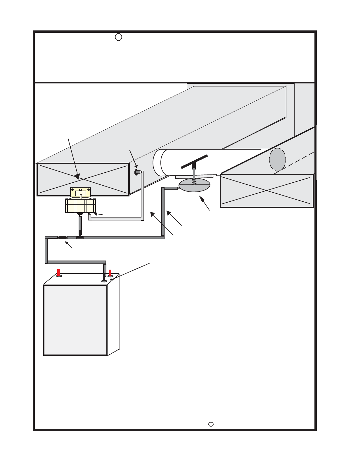
Modulating Bypass Control
Installation and Set-Up Instructions
Locate Pressure Transmitter within
24” of Bypass Damper.
Mount in Verticle position
Static Press Transmitter
Pitot Tube (3/16”OD)
Supply Duct
Bypass Duct
Return Duct
Fixed Restrictor (.012”)
Zone 1
Zone 2
Bypass
Arzel Zoning Panel
200 mps/AirBoss
“Low” port
1/4” Bulkhead Port
Spring Open Bypass Damper
1/4” OD PVC Air Tube (black w/color stripe)
3/8” OD Static Press Sensing Tube (clear)
Installation Process
1 Install the bypass duct and “Spring Open” Bypass damper.
Bypass duct should re-enter return duct as far from equipment
as possible prior to first reducer or take off. Bypass damper
should be located on the supply end of the bypass duct.
2 Mount the Pressure Transmitter on the Supply Duct within
24” of the Bypass Damper.
3 Connect the Bypass air tube (pressure line from panel) to the
Restrictor (Black) on the Pressure Transmitter tee.
(remove red caps).
4 Insert the Pressure Sensing Tube into the supply duct (5/16”
hole) on the equipment side of the bypass duct.
5 Connect the damper tubing to the Pressure Transmitter Tee,
opposite of the restrictor (remove red cap).
6 With only the smallest zone calling for cooling, adjust the
Pressure Transmitter (adj screw at the top, CW decreases
static press, CCW increases static press) for maximum branch
run velocity, with minimal air noise at the registers.
C
Copyright 2002 Arzel Zoning Technology, Inc.
Arzel® Zoning Technology, Inc.
Page 5
R
Arzel Zoning Technology, Inc.
Modulating Bypass Control
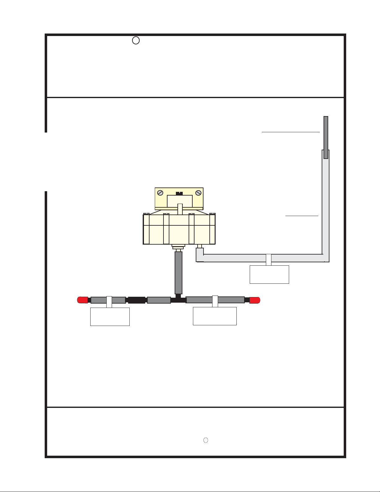
Tubing Diagram
Static Sensing Tube
Inserts into
supply duct
Clear Vinyl
Pressure Tube
Pitot Tube
To Supply Duct
To Bypass Port
at top of Panel
To “Spring Open”
Bypass Damper
Arzel® Zoning Technology, Inc.
Patent pending, Copyright Arzel R Zoning Technology, Inc.
All Rights Reserved.
 Loading...