

Page 1

INTERNATIONAL LIMITED WARRANTY
ARX Systems (ARX) warrants to the first purchaser of any ARX equipment that it is
free from defects in materials and workmanship under normal use and service.
ARX’s sole obligation under this warranty shall be to provide, without charge, parts
and labour necessary to remedy defects, if any, which appear within twelve (12)
months from date of purchase, and for a further twelve (12) months supply parts only.
This is our only warranty. It does not cover finish or appearance items, or if the
equipment has been, in ARX’s sole judgement:
•Subjected to misuse, abuse, negligence or accident;
•Repaired, worked on, or altered by persons not authorized by ARX;
•Connected, installed, adjusted or used for a purpose other than that for which it was
designed.
This warranty gives you and us specific legal rights and you may also have other
rights which may apply.
Warranty Service Procedure
Should it become necessary to have your equipment serviced under the terms of the
warranty, please follow these steps:
1. Call your ARX distributor for a Return Authorization (RA) number;
2.
Carefully
a note with a description of the problem, and a copy of the receipt showing
date of purchase. Attach these to the actual unit itself. Don’t forget to write
your name and address clearly, and include a phone number where you can
be contacted during normal business hours. Make it easy for our service
technicians to contact you if they have a question. Also, use
packing material - better to be safe than sorry.
3. Send the unit freight prepaid to ARX Systems, at the address given you with
your RA number. We will pay the return freight when the serviced unit is
returned to you.
4. We strongly recommend you insure the package. We can’t fix it if it gets lost!
Send it by UPS, Fedex, or any similar service that can track the package.
Parcel Post is
If Warranty Registration Card is missing, please write to ARX in the country of purchase, stating model and where purchased, or to ARX, PO Box 15, Moorabbin, Victoria
3189, Australia.
Or you can Email us at:
repack the unit, in its original packaging where possible, including
plenty
of
not
recommended
Level 8
8 channel
Audio Balancer and
Level Optimizer
OWNER’S
MANUAL
ARXARX
ARX Systems Pty Ltd, PO Box 15,
ARXARX
Moorabbin, Victoria 3189, Australia
PhonePhone
Phone: (03) 9555 7859
PhonePhone
International FaxInternational Fax
International Fax: +61-3 -9555 6747
International FaxInternational Fax
On the WebOn the Web
On the Web: www.arx.com.au
On the WebOn the Web
EmailEmail
Email: [email protected]
EmailEmail
FaxFax
Fax: (03) 9555 6747
FaxFax
8
LEVEL 8 Owner's Manual v 2.21 CE ©2003 ARX® LEVEL 8 Owner's Manual v 2.1 CE ©2003 ARX®
Page 2
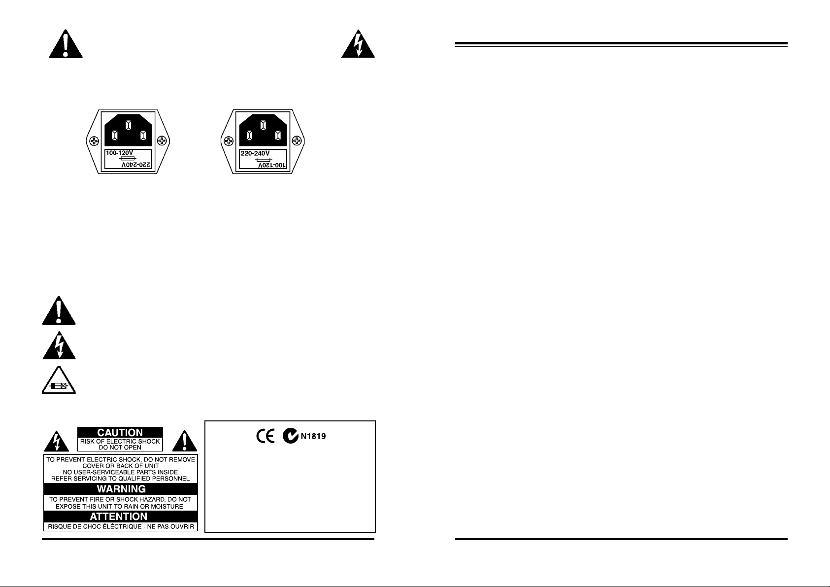
IMPORTANT - PLEASE READ THIS FIRST
This is a dual voltage unit. It is essential that you check that the voltage on the
fuseholder cover below the AC connector on the rear of the chassis is set correctly
before connecting it to AC power.
THIS IS SET FOR
100 V AC TO 120 V
AC OPERATION
To change, pull fuseholder out and rotate 180o, then push in again. Do not insert
power cable into unit until voltage has been correctly set. Do not plug power cable into
AC power until voltage has been correctly set
WARNING SYMBOLS USED ON THIS EQUIPMENT
This symbol is intended to alert you to the presence of important operating
instructions contained in this owner's manual
This symbol is intended to alert you to the presence of uninsulated dangerous voltage within the product's enclosure that may be of sufficient magnitude to constitute a risk of electric shock.
This symbol indicates that a Slow Blow fuse is used in this equipment.
Replace with same type and value only
THIS IS SET FOR
220 V AC TO 240 V
AC OPERATION
LEVEL 8 Specifications
Mode of operation 8:8 Level Optimizer / Balancer
Input Impedance 100K Ohms Unbalanced
Output Impedance 300 Ohms Balanced
Input Headroom +21dB
Output Level (max) +26dB
Signal/Noise
(@ unity gain) -94dB unweighted
-100dB A weighted
Gain 0dB Unity, Mode switch OUT, or
14 dB, Mode switch IN
(–10dB to +4dB level matching)
Dynamic Range 120dB
Output Impedance 300 Ohms Balanced
150 Ohms Unbalanced
Frequency Response 10Hz-20 KHz ±0.25dB
Distortion
(@ unity gain) .0025% THD, 0dB 1 KHz
Input Connector Type ¼”Jack
Output Connector Type Male XLR, wired Pin 1 Gnd, Pin 2 + Hot,
Pin 3 – Cold
Power Requirements 100–120 V/ 220/240 V AC
50 - 60 Hz 8 Watts (8 VA)
Size 19”W x 6”D x 1¾”H, 482 x 155 x 44mm
Weight 2.2 Kg (5 lbs)
Complies with 89/336/EEC EMC Directive,
amended by 92/31/EEC and 93/68/EEC and
meets the following standards:EN 55013 :
1990, Sections 3.2 and 3.5 EN 55020 : 1988,
Sections 4.3, 5.4, 6.2, 7.0, 8.0.
Complies with Australian Standard AS/N25
1053
2
LEVEL 8 Owner's Manual v 2.21 CE ©2003 ARX® LEVEL 8 Owner's Manual v 2.1 CE ©2003 ARX®
7
Page 3
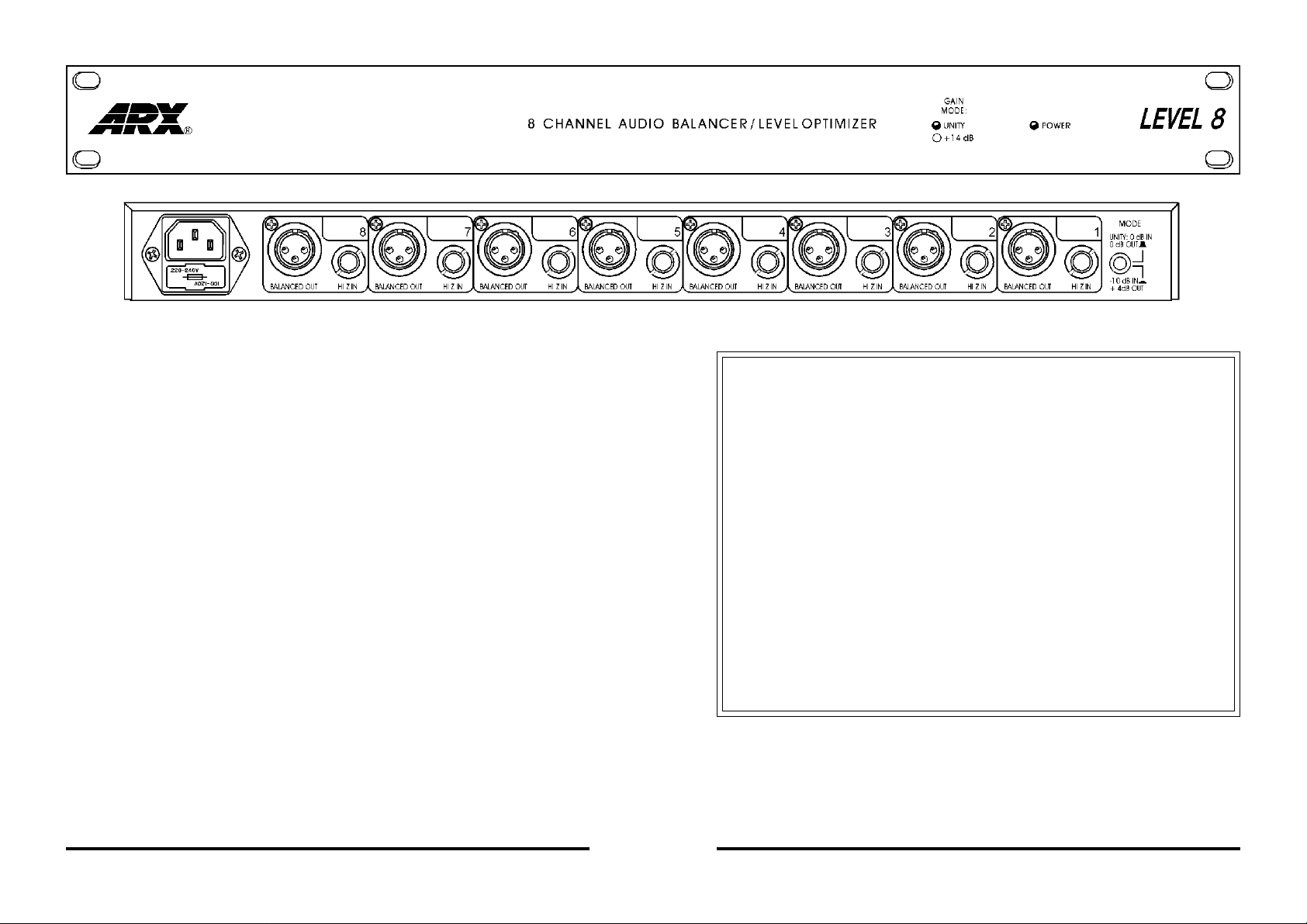
Front panel
• Unity Gain status LED
• –10dB to +4dB status LED. One of these will always be illuminated if the
unit is connected to AC mains power
Rear Panel Connectors
• Channels 1 - 8 Unbalanced Jack Input sockets. Tip + (Hot), Sleeve
Ground
• Channels 1 - 8 Balanced XLR Output sockets. Pin 2 HOT +, Pin 3 Cold –,
Pin 1 Ground
• Unity Gain or –10 to +4dB Gain Mode switch
• IEC 3 pin AC connector and integral fuseholder. Replace fuse with
correct value only: 100 - 120 V AC 1 amp, 220-240 V AC 0.5 amp.
Please also refer to voltage details on Page 2
Architects’ and Engineers’ Specifications
The unit shall be an 8 channel device that electronically converts unbalanced audio
signals to balanced signals. It shall be mounted into a standard 1 RU all steel chassis
with extruded aluminium front panel.
All Inputs shall be unbalanced jack connectors, wired Tip + (Hot), Sleeve Ground.
All Outputs shall be Balanced 3 pin XLR type, wired Pin 2 + (Hot), Pin 3 – (Cold), and
Pin 1 Ground.
The Signal to Noise ratio shall be -94dB unweighted, and -100 dB ‘A’ weighted.
The Input impedance shall be 100 K Ohms, and the Output impedance shall be 300
ohms. A switch on the rear panel shall offer the option of unity gain or -10 dB to +4 dB
level matching. There shall be corresponding status LED indicators on the front panel.
Maximum Input headroom shall be +21 dB, and maximum Output Level shall be +26 dB.
THD shall be 0.025%, 0 dB @ 1KHz.
AC power range shall be switchable 100 to 120V or 220 to 240V AC, using a standard
three pin IEC connector, with built-in fuse and voltage change switch.
The unit shall be the ARX LEVEL 8
4
LEVEL 8 Owner's Manual v 2.21 CE ©2003 ARX® LEVEL 8 Owner's Manual v 2.1 CE ©2003 ARX®
5
Page 4

Applications
• Studio, Live and Broadcast
• Sound Reinforcement
• AV Systems/CD/Audio-for-Video
• Anywhere unbalanced signals need converting to professional balanced signals
The primary benefits of running balanced low impedance signals are (a) low noise, and
(b) the ability to run a signal down long lengths of cable, e.g. multicore snakes from
one end of an auditorium to the other, without picking up noise along the way.
Any induced noise is dumped to ground via the cable shielding and also cancelled out
in the summing circuit of the balanced input receiving the signal.
Setting Up
Like so many of our best ideas, setting up your LEVEL 8 is simplicity itself.
Firstly connect the unit to AC power.
Please Note:
This is a dual voltage unit. It is essential that you check that the voltage on the
fuseholder cover below the AC connector on the rear of the chassis is set correctly
before connecting it to AC power. See Page 2 for more details on this.
Your high impedance unbalanced signal plugs into the input jack connectors of, say,
Channel 1, and the balanced output appears at the corresponding XLR output connector next to it. Continue on for all 8 channels if required.
That’s all there is to it. From the LEVEL 8 the balanced signals can be run to the next
item in the signal chain. Since each channel of the LEVEL 8 is independent of the
others, 8 different sources or up to 4 separate stereo pairs can be balanced in this
way.
The Gain Mode switch on the rear panel gives you the choice of unity gain through the
LEVEL 8, using it as a balancer only, or as a level optimizer as well, bringing the -10 dB
levels up to +4 dB (14dB overall gain).
LEDs on the front panel indicate which mode has been selected. One of these will
always be illuminated if the unit is connected to AC mains power
Introduction
Thank you for choosing this ARX LEVEL 8 Audio Balancer and Level Optimizer. We
hope you enjoy using it as much as we enjoyed creating it. As with all ARX equipment, it has undergone extensive factory calibration and ‘burn in’ before shipping. To
ensure continued trouble free use, please familiarise yourself with the contents of this
manual before using the LEVEL 8.
About the LEVEL 8
Innovation
Silently interfacing -10dB unbalanced consumer electronics with +4 dB Balanced
professional equipment has always been a problem. Hum and noise generated by a
mismatch at this point will be amplified throughout the studio, broadcast or live sound
system.
But luckily it’s a problem of the past, now that ARX has introduced the LEVEL 8, an 8
channel audio balancer and level optimizer specifically designed to handle this critical
task.
ARX’s proprietary balancing circuits take the -10 dB levels from CD players, cassette
and tape players, DAT recorders, digital 8 track recorders, and effortlessly transform
them into the balanced signals that all professional audio systems require.
Inputs are unbalanced jack connectors, and outputs are industry standard balanced 3
pin XLR type.
A Gain Mode switch on the rear panel lets you select unity gain through the LEVEL 8,
using it as a balancer only, or as a level optimizer as well, bringing the -10 dB levels up
to +4 dB (14dB overall gain). LEDs on the front panel indicate which mode has been
selected.
Housed in a rugged all steel chassis with extruded aluminium front panel, the ARX
LEVEL 8 is the ideal professional engineer’s tool for the critical task of impedance and
level converting.
6
LEVEL 8 Owner's Manual v 2.21 CE ©2003 ARX® LEVEL 8 Owner's Manual v 2.1 CE ©2003 ARX®
3
 Loading...