

Page 1

INTERNATIONAL LIMITED WARRANTY
ARX Systems (ARX) warrants to the first purchaser of any ARX equipment that it is free
from defects in materials and workmanship under normal use and service. ARX’s sole
obligation under this warranty shall be to provide, without charge, parts and labour
necessary to remedy defects, if any, which appear within twelve (12) months from date
of purchase, and for a further twelve (12) months supply parts only.
This is our only warranty. It does not cover finish or appearance items, burned voice
coils, or if the equipment has been, in ARX’s sole judgement:
•Subjected to misuse, abuse, negligence or accident;
•Repaired, worked on, or altered by persons not authorized by ARX;
•Connected, installed, adjusted or used for a purpose other than that for which it was
designed. This includes running a speaker system with the ISC leads disconnected, or
with a non-ARX crossover, or with the wrong processor.
This warranty gives you and us specific legal rights and you may also have other rights
which may apply.
AV AV
AV streamTM
AV AV
Audio and Video
Zoner/Mixer
Warranty Service Procedure
Should it become necessary to have your equipment serviced under the terms of the
warranty, please follow these steps:
1. Call your ARX distributor for a Return Authorization (RA) number;
2. Carefully repack the unit, in its original p ackaging where possible, including a note
with a description of the problem, and a copy of the receipt showing date of
purchase. Att ach these to the actual unit it self. Don’t forget to write your name and
address clearly , and include a phone number where you can be contacted during
normal business hours. Make it easy for our service technicians to contact you if
they have a question. Also, use plenty of p acking material - better to be safe than
sorry.
3. Send the unit freight prepaid to ARX Systems, at the address given you with your
RA number. We will pay the return freight when the serviced unit is returned to
you.
We strongly recommend you insure the package. We can’t fix it if it gets lost! Send it
by UPS, Fedex, or any similar service that can track the package. Parcel Post is not
recommended
If Warranty Registration Card is missing, please write to ARX in the country of
purchase, stating model and where purchased, or to ARX, PO Box 15, Moorabbin,
Victoria 3189, Australia.
Or you can Email us at: [email protected]
8 1
AVstream Owner’s Manual V1.2 © 2007 CE ARX Systems® AVstream Owner’s Manual V1.2 © 2007 CE ARX Systems®
OWNER’S MANUAL
ARX Systems Pty Ltd, PO Box 15,
Moorabbin, Victoria 3189, Australia
Phone: (03) 9555 7859 Fax: (03) 9555 6747
International Fax: +61-3 -9555 6747
On the Web: www.arx.com.au
Email: [email protected]
Page 2
IMPORTANT - PLEASE READ THIS FIRST
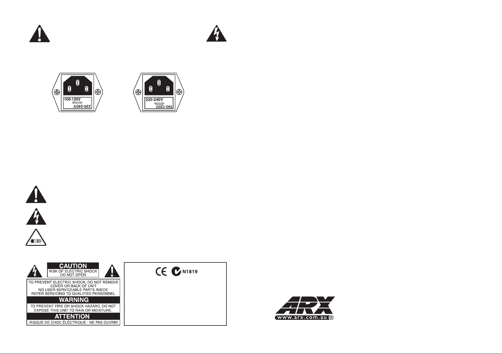
This is a dual voltage unit. It is essential that you check that the voltage on the
fuseholder cover below the AC connector on the rear of the chassis is set correctly
before connecting it to AC power.
THIS IS SET FOR 100 V
AC TO 120 V AC
OPERATION
To change, pull fuseholder out and rotate 180o, then push in again. Do not insert
power cable into unit until voltage has been correctly set. Do not plug power cable into
AC power until voltage has been correctly set
WARNING SYMBOLS USED ON THIS EQUIPMENT
This symbol is intended to alert you to the presence of important operating
instructions contained in this owner's manual
This symbol is intended to alert you to the presence of uninsulated
dangerous voltage within the product's enclosure that may be of sufficient
magnitude to constitute a risk of electric shock.
This symbol indicates that a Slow Blow fuse is used in this equipment.
Replace with same type and value only
THIS IS SET FOR 220 V
AC TO 240 V AC
OPERATION
AVstream™Specifications
Input Impedance Mic 4 KOhms balanced
Line 100 KOhms unbalanced
Input Gain Mic Variable 20 dB to 60 dB with rear trim control
Line –10 to +10 dB
Output Level (Max) + 21dB
Signal to Noise ratio@ Unity
-90 dB ‘A’ weighted Note: All inputs @ unity, Master @ unity
Distortion @ Unity Gain
Below .005% 100Hz to 10 KHZ
Dynamic Range 115 dB
Mic Channel EQ
Low 100Hz 15dBCut/Boost
High 10KHz 15dBCut/Boost
Zone EQ
Loudness Control (Out) Flat
(In) 50z and 10KHz up to max +6dB
Level Control oo to +6dB Gain (0 to 11)
Hi Z Input Connectors Phono (RCA type)
Video Type Composite Video
Video Input Connectors RCA type
Balanced Output Connectors Male XLR: Pin 1 Ground, Pin 2 +, Pin 3 –
Video Output Connectors RCA type
Frequency Response 20Hz—20KHz ±1dB
Power Requirements 100-120/220-240 V AC 50/60 Hz 8VA (8 watts)
on 3 pin IEC connector
Weight 5 lbs/2.2 Kg
Dimensions 19"W x 1¾"H x 6"D, 482 x 44 x 155mm
Complete online documentation is available on the ARX website:
www.arx.com.au/AVstream.htm
Complies with 89/336/EEC EMC Directive,
amended by 92/31/EEC and 93/68/EEC and
meets the following standards:EN 55013 : 1990,
Sections 3.2 and 3.5 EN 55020 : 1988, Sections
4.3, 5.4, 6.2, 7.0, 8.0.
Complies with Australian Standard AS/N25 1053
2
AVstream Owner’s Manual V1.2 © 2007 CE ARX Systems® AVstream Owner’s Manual V1.2 © 2007 CE ARX Systems®
Specific queries can be emailed to the factory at [email protected]
Our policy is one of continuous improvement, and therefore designs may change
without notice. However, unless otherwise stated, specifications will always equal or
exceed those previously given. ARX® is a Registered Trade Mark of ARX Systems Pty
Ltd. AVstream™ is a trade mark or ARX Systems Pty Ltd. Any other names and
trademarks are used for information purposes only, and no other intent is expressed
or implied
7
Page 3
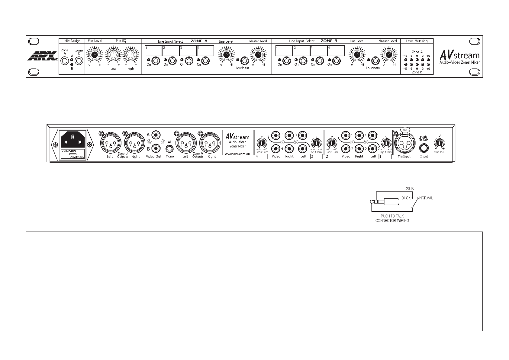
Front Panel
• Microphone Zone assign switches and LEDs
• Microphone Level control
• EQ controls for the microphone
• Zone A program source switches, with label panels and LED
indicators to show active source
Rear Panel
• IEC 3 pin AC connector and integral fuseholder. Replace fuse with correct
value only: 100 - 120 V AC 1 amp, 220-240 V AC 0.5 amp. Please also
refer to voltage details on Page 2
• Zone A and B Balanced XLR Outputs wired Pin 1 Ground, Pin 2+ (Hot), Pin
3 – (Cold)
• Zone A and B Composite video Outputs wired Sleeve Ground, Cetre Pin+
(Hot)
• All Outputs to Mono switch
• Sources 1, 2, 3 and 4 Input Gain trim controls
ARCHITECTS’ AND ENGINEERS’ SPECIFICA TIONS
The signal processor shall be mounted in a steel chassis six inches deep and one rack unit high.
The unit shall be a Zoner/Mixer, i.e, it shall accept inputs from four separate stereo sources and
composite video sources as well as a microphone, and send them to two separate zones. A
switch on the rear panel shall switch the output of the two zones to either stereo (Left and
Right), or Mono.
The microphone input shall have a level control and two way Equalisation controls. The microphone connector shall be a balanced XLR input with an Input impedance of 4 K Ohms. There
shall also be an input for a ducker control to attenuate line inputs by 20 dB, and LEDs to indicate
microphone status. The microphone shall be able to be routed to either or both output zones.
Each Line source shall have High Z Left and Right phono (RCA type) connectors, with associated Gain trim controls –10dB to +10 dB on the rear panel, and an overall line level control on
the front panel. A switch and status LED on the front panel shall indicate which source is active
• Zone A Line level control
• Zone A Loudness switch and status LED
• Zone A Master Level control
• Zone A and B Output Level LED metering
(Zone B functions identical to Zone A)
• Sources 1, 2, 3 and 4 Phono (RCA type) ASudio and V ideo input connectors
• Balanced XLR microphone connector
• Microphone Gain trim control
• TRS jack connector for Mic
override (Press-to-talk ducker)
to attenuate line inputs by 20
dB. Wired so that shorting Tip
and Ring enables ducker
in each zone. These switches shall be interlocking so that only one of the four input sources per
zone can be selected at one time.
Each Zone shall have an Equalisation control and the option of Local or Remote Master output
level control. Each Master output shall have a dedicated 5 LED metering display
Input source impedance shall be 100K Ohms, and the input headroom shall be +21dB. The
frequency response (all channels and masters) shall be 20 Hz to 20 KHz, ±1dB. The Output
impedance shall be 300 ohms balanced, and the maximum Output level shall be +21dB, with a
Signal to Noise ratio at unity of -90 dB ‘A’ weighted. Audio Output connectors shall be Balanced
XLR type; Video Output connectors shall be RCA type. THD shall be below .005%, 100Hz to 10
KHZ, and the unit shall have a dynamic range of 111dB.
Power shall be supplied via a removable mains cable, connecting to an IEC connector with an
integral fuse and voltage change switch on the unit’s rear panel.
The Zoner/Mixer shall be the ARX AV Stream.
4
AVstream Owner’s Manual V1.2 © 2007 CE ARX Systems® AVstream Owner’s Manual V1.2 © 2007 CE ARX Systems®
5
Page 4

Using the AVstream
Setting up your AVstream is very straightforward and intuitive.
Firstly, connect the unit to AC power. Please Note that it is a dual voltage unit. It is
essential that you check that the voltage on the fuseholder cover below the AC
connector on the rear of the chassis is set correctly before connecting it to AC power.
See Page 2 for more details on this.
Getting started
1. Connect the Zone A and B balanced output s to their respective amplifiers, the video
outputs to their associated screens, then switch the amplifiers on. Don’t turn them
up just yet.
2. Connect the audio and video input sources to the appropriate RCA connectors as
marked on the rear panel, and mark in both zones on the front panel what each of
them is: CD, Video, Radio, etc.
3. Set the Input trim controls next to each RCA at 0 (12 o’clock)
4. Set all external units to play ,
5. Turn up the amplifiers about half way, and switch on the screens
6. Press any line source switch on Zone A, (or B - whichever one you will be able to
listen to or view)
7. Bring up the Zone A Master level until you can hear something. If all the sources
are connected and playing, then something will come out of the speakers!
8. Switch through each of the sources on Zone A, while adjusting the Input trim
controls on the rear panel. Aim to get each of the sources at around the same
volume, so the when you switch through them there is no variation in level from
one to the other.
9. Turn the amplifiers up to their normal operating level, then adjust the Zone Level
control until you have the system sounding correct.
That’s it for the Line inputs. Leave it playing while we go to the Microphone.
1. Connect the Microphone lead to the balanced XLR input on the rear panel. If you
have a separate push-to-talk connector , plug that in as well.
2. Set the Input Gain trim control next to the XLR connector to the tick (12 o’clock)
3. Switch the Mic to the Zone required - A, B or both, with the front p anel switches. If
you have a push-to-talk button on the mic, press it down.
4. Speak into the mic while adjusting the mic level control on the front panel until you
reach the output level required.
5. Adjust the mic EQ for the best sound, and that’ s just about it!
Introduction
Thank you for choosing this ARX AVstream. We hope you enjoy using this unique
product as much as we enjoyed creating it. As with all ARX equipment, it has
undergone extensive factory testing and ‘burn in’ before shipping. To ensure
continued trouble free use, please familiarise yourself with the contents of this manual
before using.
About the AVstream
The ARX AVstream is a unique ‘user-friendly’ Zoner/Mixer, enabling a choice of four
stereo audio and video sources to be routed to each of two zones.
• Intuitive Layout
The linear ergonomic flow of the front panel controls, coupled with the visual feedback
of level settings and source selection makes using the AVstream totally intuitive, even
for casual staff with no prior experience.
Up to four stereo audio sources and associated composite video sources as well as a
microphone can be connected to the AVstream, such as: DVD/CD decks, TV/
Satellite/video + audio, Juke Box/Karaoke systems. Interlocking switches and an
associated status LEDs for each source ensure that there is no risk of accidentally
selecting two sources for the one zone.
A front panel switch turns the microphone on or off, and there is also provision to
connect a push-to-talk signal for priority/evac override.
Dual colour-coded LED meters show output levels for each zone.
• Superb Audio Quality
Every day, ARX Audio interface products solve audio problems for thousands of
people around the world. We’re fanatical about audio quality because we’re betting
that you are, too. That’s why we have comprehensive EQ control for the microphone,
and for both Zones as well, rather than a single ‘Tone’ knob, to ensure that you and
your clients get the best possible sound.
Ease of use, flexible setup, superb audio quality - that’s the ARX AVstream promise!
Congratulations - you’ve just set up the complete AVstream system.
6
AVstream Owner’s Manual V1.2 © 2007 CE ARX Systems® AVstream Owner’s Manual V1.2 © 2007 CE ARX Systems®
3
 Loading...