


Aruba Networks
MSR4000 Installation Guide
0511135-02

Copyright 2005-2012 by Aruba Networks, USA. All rights reserved.
Statement of Conditions
In the interest of improving internal design, operation function, and/or reliability, Aruba
Networks reserves the right to make changes to produc ts described i n this docum ent without
notice. Aruba Networks does not assume any liability that may occur due to the use or
application of the product(s) described herein.
DISCLAIMER: LIMITATION OF LIABILITY
1.Before installation, it is strongly recommended and request ed that users pay particular
attention to the safety warnings in the sequentially detail ed operation procedures within the
manual. If there is any uncertainty or incapabili ty of solving problems , contact the company’s
customer support center. Please DO NOT incur any risk or try to verify situations by yourself.
Otherwise, any consequence caused by the attempt shall be completely due to the user
himself.
2.Periodically check whether the installed MSR4000 is damaged, worn-out or poses any
danger. Any actual proof, sign, or phenomenon of the afore-mentioned situations should be
brought to the attention of the company at the point of sale. Please DO NOT attempt to
repair the product or replace any component. The company shall not be liable for any
consequence arising out of or relating to the users’ attempt to repair the product, including
but not limited to damages, disuse, short circuit, fire, bodily injury, etc.
3. Users shall purchase or use the company’s MSR4000 voluntarily. Users shall understan d
on their own initiative and abide voluntarily by polici es, regulat ions , or laws of their respective
nation or local territories. The consequence arising out of or relati ng to any violation of the
local laws or regulations by the user shall be solely attributed to the user himself, and t he
company shall not be liable.
4. The company disclaims any and all warranties and guarantees, express, implied or
otherwise, arising, with respect to the MSR4000 products or services, including but not
limited to the warranty of merchandisa bility, the warranty of fitness for a part icular purpose,
and any warranty of non-infringement of the intellectual property rights of any third party.
MSR4000 Installation Guide 1
Liability of the company for loss is limited to the total amount paid to the company by the
customer during the previous calendar year. The company will have no obligation or liability,
whether arising in contract (including Warranty), tort (including active, passive or imputed
negligence, strict liability or product liability) or otherwise for any special, incidental,
consequential, or indirect damages including but not limited to loss of use, loss of data,
business interruption, loss of revenue , loss of business, or other financial los s arising out of
or in connection with any of the products or other goods or services furnished by the
company under this manual, even if advised of the possibility of such damages.
5.It shall never be understood that this manual expresses or implies to any customer or
any third party authority or transfer of any rights. The company reserves fully the final
interpretation of the MSR4000 and this manual.
Safety Warnings
The MSR4000 must be installed by trained professionals or installation technicians. All
warnings below must be read and understood before installation.
General Safety Warnings
You can be killed or injured if performing antenna installation near electrical
power lines. Carefully read and follow all inst ructions in this guide. Please be sure t here
are no high voltage and electronic fields nearby.
Working Aloft Warning
When working on tower or roof, i ndividuals must wear safety belts. Tools must
be tied to the individual using them. Workers below must wear safety helmets.
Lightning Activity Warning
Make sure not to connect or disconnect cables during periods of lightning
activity.
A surge protective device should be installed to prevent potential damage from very high
surges, for instance, the peak surges caused by lightning.
2 MSR4000 Installation Guide
Explosive Device Proximity Warning
Do not operate wireless network devices close to explosive merchandise or in
explosive environments if devices are not certifi ed for operation in such an e nvironment ,
for example, in the vicinity of a gas station
Antenna Placement Warning
.
Do not install any antenna near overhead power lines or other electric light, or
where the antenna can come into contact with such circuits.
Antenna Selection Warning
Use the DC grounding antenna with lightning protection to prevent surge and
static electricity.
Grounding Warning
Always remember to protect your MSR4000 system by installation of grounding
lines. The ground connection must be complete before connecting power to the
MSR4000 enclosure. The requirement of grounding is to make sure the resistance
between the ground termination point and the gro unding tier is less than 5 ohm.
Power Installation Warning
The installation of the power switch must be performed by a trained prof essional
technician.
The power switch is not supplied with the MSR4000. The power cord must be
assembled by a professional installer, and the final assembly must comply with related
requirements.
MSR4000 Installation Guide 3
Solar Radiation and High Temperature Protection
Pay attention to the level of sunlight. This could cause an increase in the working
temperature of the MSR4000. Make sure the work ing temperature of the MSR4000 is
not higher than the specifications listed in this document.
A solar shield is provided in the Aruba standard package and should be installed to
protect any outdoor MSR4000. The Aruba Warrantee policy does not cover those
outdoor products for which solar shields are not installed. Please contact Aruba
technical support engineers for detailed inf ormation.
RF Device Protection
Before powering up the MSR4000, we recommend that the RF ports are
connected to antennas or valid loads. RF modules wit h less than 100mW power may
work in a test environment without antennas or load connect ions, provided the duration
of operation is less than 30 minutes.
Protection on unused RF module
The unused RF interface must be closed via configuration command and its protect ive
cap must be wrapped up by waterproof PV C tape to prevent it from falling off. Otherwise,
the RF module may be damaged. Aruba will not take any responsibility for such damage.
FCC Certificate
Changes or modifications not expressly approved by the party responsible for compliance
could void the user's authority to operate the equipment.
REMINDER
This device complies with Part 15 of the FCC Rules. Operati on is subject t o the following two
conditions: (1) This device may not cause harmful interference, and (2) This device must
accept any interference received, including interference that may cause undesired operati on.
4 MSR4000 Installation Guide

NOTICE
This equipment has been tested and found to comply with the limits for a Class B digital
device, pursuant to part 15 of the FCC Rules. These limits are designed to provide
reasonable protection against harmful interference in a residential installation. This
equipment generates, uses, and can radiate radio frequency energy and, if not installed and
used in accordance with the instructions, may cause harmful interference to radio
communications. However, there is no guarantee that interference will not occur in a
particular installation. If this equipment does cause harmful interf erence to radio or televisio n
reception, which can be determined by turning the equipment off and on, the user is
encouraged to try to correct the interference by one or m ore of the following measures:
• Reorient or relocate the receiving antenna.
• Increase the separation between the equipment and receiver.
• Connect the equipment into an outlet on a circuit different from that to which the
receiver is connected.
• Consult the dealer or an experienced radio/TV technician for help.
Precautions
The radiated output power of this device is below the FCC radio frequency exposure limits
based on that human proximity to the antenna shall not be less than 34cm during normal
operation.
IC notice
To reduce potential radio interference to other users, the ant enna type and its gain should be
so chosen that the equivalent isotropic radiated po wer (EIRP) i s not more than that permitted
for successful communication.
Proper Disposal of Aruba Equipment
For the most current information about Global Environmental Compliance and Aruba
products, see our website at www.arubanetworks.com.
MSR4000 Installation Guide 5
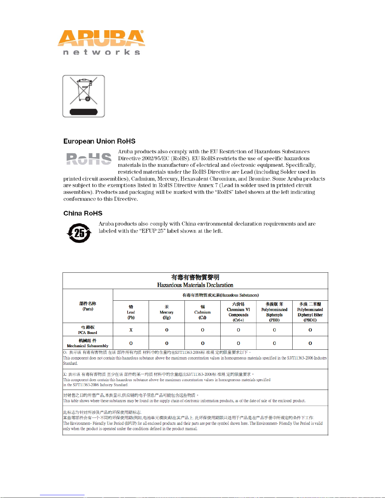
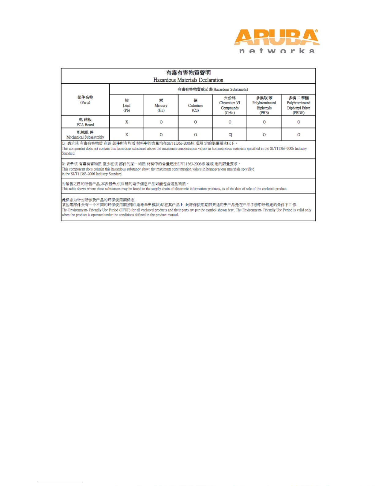
Waste of Electrical and Electronic Equipment
Aruba products at end of life are subject to separate collection and
treatment in the EU Member States, Norway, and Switzerland and
therefore are marked with the symbol shown at the left (crossed-out
wheelie bin). The treatment applied at end of life of these products in
these countries shall comply with the a pplicable national laws of countries
implementing Directive 2002/96EC on Waste of Electrical and Electronic
Equipment (WEEE).
MSR4KP
6 MSR4000 Installation Guide
MSR4KAC
MSR4000 Installation Guide 7

Table of Contents
1 PRODUCT OVERVIEW ............................................................................................................................................. 9
1.1 INTERFACES ..................................................................................................................................................... 9
1.2 LED STATUS INDICATORS ............................................................................................................................. 10
2 INSTALLATION PREPARATIONS ....................................................................................................................... 14
2.1 PACKAGE CONTENTS ..................................................................................................................................... 14
2.2 PREPARING INSTALLATION TOOLS ................................................................................................................. 15
2.3 EXAMINING THE INSTALLATION SITE ............................................................................................................. 15
3 WEATHERPROOFING CONNECTIONS ............................................................................................................. 16
3.1 REQUIRED ITEMS AND TOOLS ........................................................................................................................ 16
3.2 TYPES OF CONNECTIONS ................................................................................................................................ 16
3.3 IMPORTANT POINTS TO REMEMBER ............................................................................................................... 18
3.4 WEATHERPROOFING ANTENNAS CONNECTED DIRECTLY TO THE MSR4000 ................................................. 18
3.5 WEATHERPROOFING CABLE CONNECTIONS ................................................................................................... 22
4 MSR4000 INSTALLATION ...................................................................................................................................... 25
4.1 INSTALLING THE MSR4000 ON A POLE .......................................................................................................... 25
4.2 INSTALLING THE MSR4000 ON A WALL ........................................................................................................ 29
4.3 GROUNDING THE MSR4000 ........................................................................................................................... 31
4.4 CONNECTING THE RF CABLE ......................................................................................................................... 32
4.5 CONNECTING THE ETHERNET CABLE ............................................................................................................. 34
4.6 CONNECTING THE POWER CABLE (MSR4KAC) ............................................................................................ 36
5 NOTE ........................................................................................................................................................................... 39
6 PRODUCT SPECIFICATIONS ................................................................................................................................ 40
7 CONTACTING SUPPORT ....................................................................................................................................... 42
8 MSR4000 Installation Guide
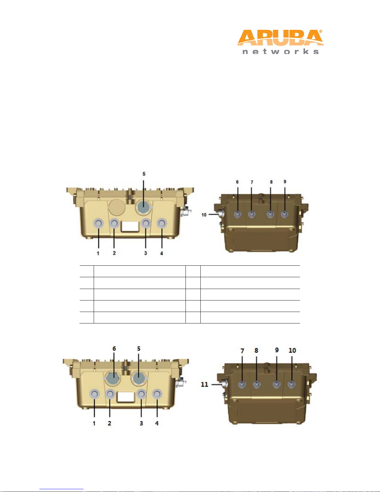
1 Product Overview
1
Antenna 2 (Radio 2)
6
Antenna 1 (Radio 0)
2
Antenna 2 (Radio 1)
7
Antenna 1 (Radio 3)
3
Antenna 2 (Radio 3)
8
Antenna 1 (Radio 1)
5
Ethernet Interface
10
USB Console Interface
There are two versions of the MSR4000, which mainly differ in the way they receive power.
MSR4KP: PoE powered
MSR4KAC: AC powered (100-240VAC)
1.1 Interfaces
Figure 1-1 Interfaces on the MSR4KP
4 Antenna 2 (Radio 0) 9 Antenna 1 (Radio 2)
Figure 1-2 Interfaces on MSR4KAC
MSR4000 Installation Guide 9

1
Antenna 2 (Radio 2)
7
Antenna 1 (Radio 0)
2
Antenna 2 (Radio 1)
8
Antenna 1 (Radio 3)
3
Antenna 2 (Radio 3)
9
Antenna 1 (Radio 1)
4
Antenna 2 (Radio 0)
10
Antenna 1 (Radio 2)
6
AC Power Interface
5 Ethernet Interface 11 USB Console I nterface
1.2 LED Status Indicators
The MSR4000 includes visual indicators for power, link, and radio status.
Figure 1-3 MSR4KP LED Layout
The following table lists the meanings of the LEDs on the MSR4KP:
10 MSR4000 Installation Guide
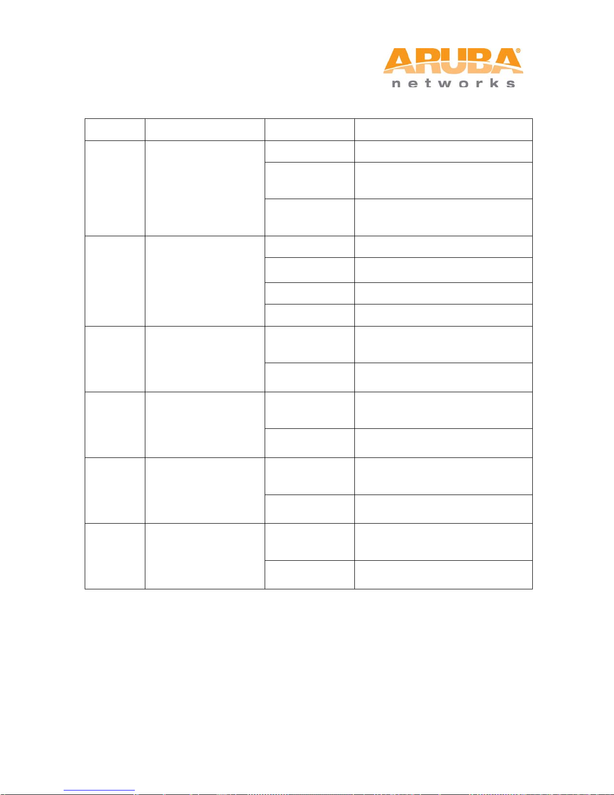
Table 1-1 MSR4KP LED status indicators
Device has power but does not yet
to a gateway (portal) node
gateway (portal) node
10/100 Mbps Ethernet link
negotiated
Radio 0 is not providing either
service
service
Radio 2 is not providing either
service
Radio 3 is not providing either
service
LED Function Indicator Status
Off No power to device
P/S Power
ETH Network Link Status
R0 Radio 0 Status
R1 Radio 1 Status
On (Amber)
On (Green)
Off No uplink on the Ethernet port
On (Amber)
On (Green) 1000 Mbps Ethernet link negotiated
Blinking Traffic on Ethernet link
Off
On (Blue)
Off
On (Blue)
have a mesh network routing path
Device has power and has found a
mesh network routing path to a
access (SSID) or backhaul (mesh)
Radio 0 is providing access (SSID)
service or backhaul (mesh) service
Radio 1 is not providing either
access (SSID) or backhaul (mesh)
Radio 1 is providing access (SSID)
service or backhaul (mesh) service
R2 Radio 2 Status
R3 Radio 3 Status
MSR4000 Installation Guide 11
Off
On (Blue)
Off
On (Blue)
access (SSID) or backhaul (mesh)
Radio 2 is providing access (SSID)
service or backhaul (mesh) service
access (SSID) or backhaul (mesh)
Radio 3 is providing access (SSID)
service or backhaul (mesh) service
Off
No power to device
Device has power but does not yet have a
(portal) node
Device has power and has found a mesh
node
Port on (25kΩ)
exceeded
On (Yellow)
10/100 Mbps Ethernet link negotiated
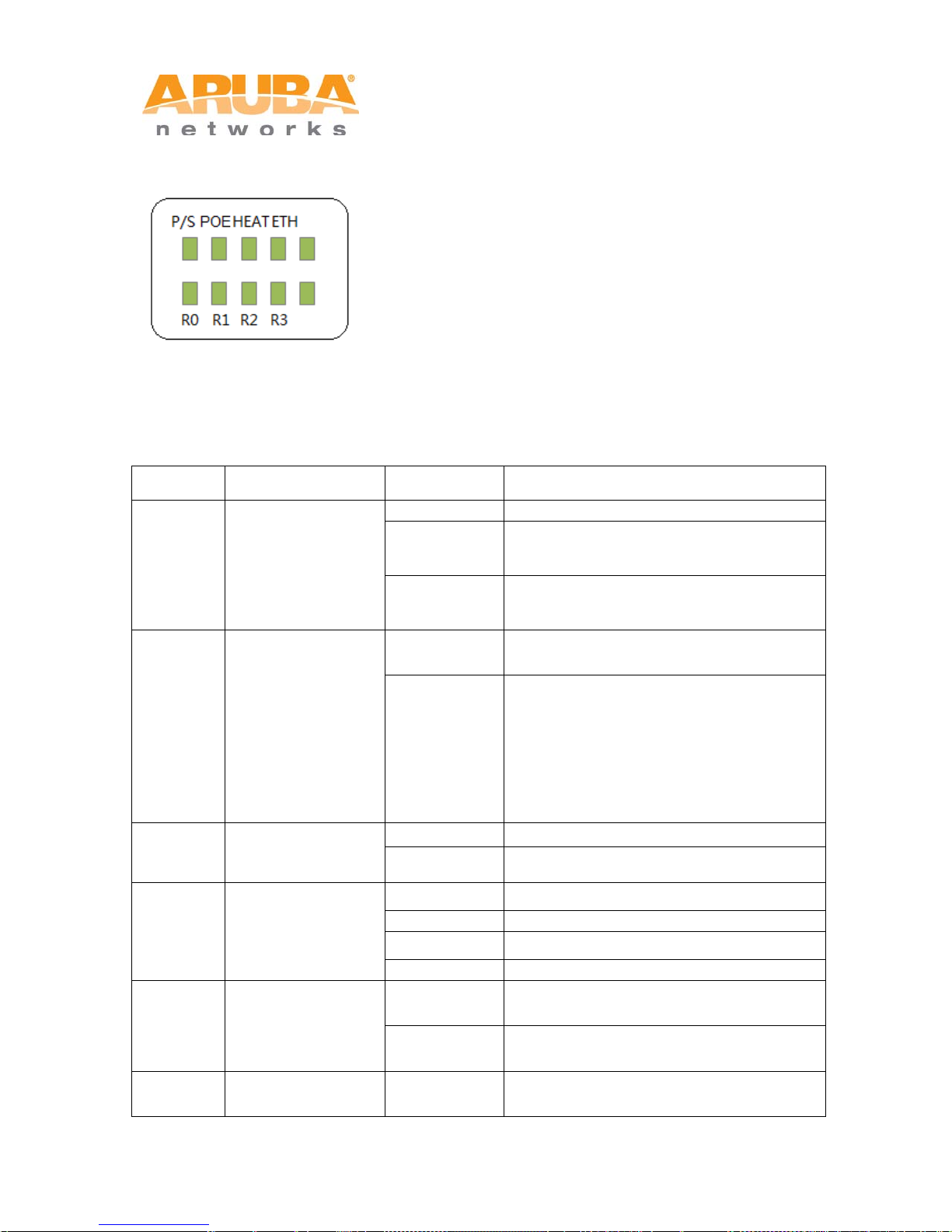
Figure 1-4 MSR4KAC LED Layout
The following table lists the meanings of the LEDs on the MSR4KAC:
Table 1-2 MSR4KAC LED status indicators
LED Function Indicator Status
P/S Power
POE
HEAT
ETH Network Link Status
R0 Radio 0 Status
Displays PSE power
output status
Displays the heating
status of low
temperature
On (Amber)
On (Green)
Off
Green
Off Device is not in heating status
Blinking (Blue) Device is heating
Off No uplink on the Ethernet port
On (Green) 1000 Mbps Ethernet link negotiated
Blinking Traffic on Ethernet link
Off
On (Blue)
mesh network routing path to a gateway
network routing path to a gateway (portal)
Non-powered device (0Ω<Rport<200Ω) or
Port open (Rport>1MΩ)
• 1 Flash: Low signature resistance
(300Ω<Rport<15kΩ)
• 2 Flashes: High signature resistance
(33kΩ<Rport<500kΩ)
• 5 Flashes: Port overload fault
• 9 Flashes: Power management allocation
Radio 0 is not providing either access
(SSID) or backhaul (mesh) serv ice
Radio 0 is providing access (SSID) service
or backhaul (mesh) service
R1 Radio 1 Status Off
12 MSR4000 Installation Guide
Radio 1 is not providing either access
(SSID) or backhaul (mesh) serv ice

On (Blue)
Radio 3 is not providing either access
(SSID) or backhaul (mesh) serv ice
Radio 1 is providing access (SSID) service
or backhaul (mesh) service
Off
R2 Radio 2 Status
On (Blue)
Off
R3 Radio 3 Status
On (Blue)
Radio 2 is not providing either access
(SSID) or backhaul (mesh) serv ice
Radio 2 is providing access (SSID) service
or backhaul (mesh) service
Radio 3 is providing access (SSID) service
or backhaul (mesh) service
Note
Starting with MeshOS 4.5, you can turn off the LEDs in the MSR4000 devic es usi ng the
WMI and the CLI. The LEDs are enabled by defaul t. This option may be used to disable
the LED lights in a MSR4000 device that is mounted in an elevated place on the city
streets or residential areas, to avoid unwanted attention or disturbance. This feature
turns off only the LED lights that indicate the software status, for example the RF. The
LEDs that indicate the hardware status, for example Power, P/S, POE, and ETH,
cannot be turned off using this feature. For additional details, refer to the Aruba
MeshOS User Guide and the Aruba MeshOS Command Reference Guide.
MSR4000 Installation Guide 13

2 Inst a l lation Preparations
This chapter describes the preparations for MSR4000 installation, including checking
package contents, preparing installation t ool s, and selection of installation sites.
2.1 Package Contents
• Aruba MSR4000 AirMesh Router
• MSR4000 Mounting Bracket
• Solar Shield
• Pole Anchors x 4
• M4 x 16 bolts, flat washers and spring washers x4 (These bolts are attached to the
solar shield)
• M4 x 16 bolts, flat washers and spring washers x2
• M6 x 30 bolts, flat washers and spring washers x2
• M4 x 12 bolt, external-to oth washer, and OT copper lug x1
• M8 x 110 bolt, flat washers, spring washers, and nuts x4
• Metal Weatherproof Caps x2 - for use on unused antenna interfaces
• RJ-45 Connector Ki t wi th metal RJ-45
• USB Console Cable
• Installation Guide
• Quick Start Guide
Note
Inform your supplier if there are any incorrec t, missing, or damaged parts. If possible,
retain the carton, including the original packing materials. Us e these materials to repack
and return the unit to the supplier if needed.
14 MSR4000 Installation Guide

2.2 Preparing Installation Tools
Type
Tools
Screwdriver, adjustable spanner, vice, safety belt, hard hat, power
The following tools may be required while installing a MSR4000:
Table 2-1 Installation Tools List
board (220 VAC or as required by local regulation), POE power
General tools
injector, crimping pliers, electric sol deri ng iron, welding wire, PVC
insulation tape, adhesive insulation tape, strap, insulation tools
2.3 Examining the Installation Site
1. For sites that are providing mesh connections to other units, installation location
should be selected to provide line-of-sight (LOS) with clearanc e of obstacles of at
least 60% of the first Fresnel zone.
2. If the area is not LOS secured, non LOS area could be covered as well, but the
distance of coverage and area of coverage are dec reased; mor e sit es are neede d to
provide coverage for same area than as compared to the LOS scenario.
3. Interference must be considered in site selection. New site should avoid known
interference, unless the interference is controllable.
4. Keep the MSR4000 away from plac es that are susc eptible to hig h temperatur e, dust,
harmful gas, inflammable, explosive, electromagnetic interference (high power radar,
radio station and transformer), unstable voltage, heavy vibration, or loud noise. In
engineering design, the site shoul d be selected according to the network planning
and technical requirements of communications equipment, as well as the
considerations such as climate, hydrology, geolo gy, earthquake, electric power, and
transportation.
MSR4000 Installation Guide 15

3 Weatherproofing Connections
Weatherproofing your antenna and/or cable connections on your outdoor router is essential
to reliability and longevity of your product. This process prevents water from entering the
router or the antennas through the connectors.
A good weatherproofing job consists of three wrappings:
1. Electrical tape
2. Butyl rubber
3. Electrical tape
The first wrapping of tape should be at least two lay ers, followed by a single wrap of butyl
rubber, and four-layer wrap of electrical tape. This provides good protection from water, heat,
and other potential hazards that could damage you r AP or antennas.
Additionally, wrap your connections such that water is always directed down and away from
connections.
3.1 Required Items and Tools
• 3/4” (19 mm) Vinyl Electrical Tape (waterproofing type)
• Butyl Rubber Tape
• Knife or Box Cutter
3.2 Types of Connections
The following sections provide guidance on weat herproofing directly connected antennas
(Figure 3-1) and cable connections (Figure 3-2). The same materials are needed for
weatherproofing both types of connections but the procedure is slightly different. For
weatherproofing directly connected antennas, see the Weatherproofing Antennas Connected
Directly to the MSR4000 section. For weatherproofing cable connections, see the
Weatherproofing Cable Connections section.
16 MSR4000 Installation Guide

Figure 3-1 Antennas Connected Directly to the MSR4000
Figure 3-2 Cable connections
MSR4000 Installation Guide 17

3.3 Important Points to Remember
• Do not cover the weep holes on the antennas. Doing so can restrict the releas e of
condensation from the antennas.
• Proper weatherproofing is not a fast process. Set aside ample time to complete the
steps outlined below.
• When wrapping, make each layer of tape as flat as possible. Wrinkles and folds in
the tape create places for water and moisture to gather.
3.4 Weatherproofing Antennas Connected Directly to the MSR4000
First Wrapping of Tape
Note
The following instructions assume that you have installed a lightning arrestor between
your router and the antennas.
1. Before wrapping the antennas, locate the weep hol es (Figure 3-1). Weep holes allow
condensation that has built up inside the antenn a to escape.
2. Prepare the antenna connector and the light ning arrestor by cleaning and drying it.
3. Cut a 4” (100 mm) strip of electrical tape from t he roll. Pre-cutting the tape into strips
makes it easier to maneuver the tape around the antennas and other components of the
router’s case.
4. Beginning at the antenna connector on t he router and stopping three-quarters of the
length of the antenna connector, tightly wrap the connec tion with a layer of the 3/4”
(19mm) electrical tape. Overlap the tape to a half-width.
5. Repeat steps 3 and 4 until the wrapping extends all the way to the router’s case.
18 MSR4000 Installation Guide

Figure 3-3 First Wrapping of Tape
Wrapping of Butyl Rubber
1. Cut a 3/4” (19 mm) strip of butyl rubber.
2. Wrap the strip of rubber around the taped connector (F i gure 3-4).
3. Join the two ends by pushing them together until t here i s no longer a seam (Figure 3-5).
MSR4000 Installation Guide 19

Figure 3-4 Butyl Rubber Placement
Figure 3-5 Butyl Rubber Wrap
20 MSR4000 Installation Guide

Second Wrapping of Tape
1. Cut a 4” (100 mm) strip of electrical tape from the roll.
2. Where you begin wrapping depends on the orientation of the antenna. Water should
flow in the opposite direction of the wrapping to prevent water from entering the
connector between the layers of tape. Therefor e, if the antenna is facing up, you should
begin wrapping at the router end of the connect or. This will ensure that your fourth and
final layer will be layered correctly. Conversely, if your antenna is facing down, you
should begin wrapping on the antenna end of the connec tor.
3. After completing the fourth layer of tape, check your work to ensure there are no places
where water can collect. If there are, you must smooth out those areas with additional
layers of tape or remove the weatherproofing and begi n again.
Figure 3-6 Completed Wrapping (Antenna on Top of the Router)
4. Repeat this process for all connectors.
MSR4000 Installation Guide 21

3.5 Weatherproofing Cable Connections
First Wrapping of Tape
1. Prepare the antenna connector by cleaning and drying it.
2. Cut a 4” (100 mm) strip of electrical tape from t he roll. Pre-cutting the tape into strips
makes it easier to maneuver the tape around the connectors and other components but
is not required.
3. Beginning at the top of the connector, t ight l y wrap the connection with a layer of the 3/4”
(19mm) electrical tape. Overlap the tape to a half-width.
4. Repeat steps 3 and 4 until the wrapping extends all the way to the cable’s insulation.
Figure 3-7 First Wrapping of Tape
Wrapping of Butyl Rubber
1. Cut a piece of butyl rubber large enough to wrap around the connector and extended
past the first layer of tape.
2. Wrap the strip of rubber around the taped connector (F i gure 3-8).
3. Join the two ends by pushing them together until t here i s no longer a seam (Figure 3-9).
22 MSR4000 Installation Guide

Figure 3-8 Butyl Rubber Placement
Figure 3-9 Butyl Rubber Wrap
Second Wrapping of Tape
1. Cut a 4” (100 mm) strip of electrical tape from the roll.
2. Using 3/4” (19mm) electrical tape, begi n wrapping at the connector and create four
layers.
3. After completing the fourth layer of tape, check your work to ensure there are no places
where water can collect. If there are, you must smooth out those areas with additional
layers of tape or remove the weatherproofing and begi n again.
MSR4000 Installation Guide 23

Figure 3-10 Completed wrapping
4. Repeat this process for all connecti ons.
24 MSR4000 Installation Guide

4 MSR4000 Installation
{M6 x30 bolt, flat washer, spring
4.1 Installing the MSR4000 on a pole
The mounting bracket assembly for inst alling MSR4000 includes: solar shield, a pair of pol e
anchors, a mounting bracket, and bolts. MSR4000 can be mounted on a pole or wall. Pole
diameter must be 40 to 60 mm at the position where the MSR4000 will be mounted.
Note
If using M8 x150 long bolts (not provided in the box shipped with MSR4000), the
MSR4000 can be mounted on a pole with 96mm diameter.
Figure 4-1 Bolts
{M4 x16 bolt (flat washer, spring
1
washer)}x4
{M4 x12 bolt, external-tooth washer,
4
OT copper lug}x1
2 {M4 x16 bolt}x2 5
3
washer}x2
Step 1 Fix the solar shield on MSR4000 using the four M4 x16 bolts (with flat and spring
washers) on the four screw holes of the MSR4000 (Figure 4-2).
MSR4000 Installation Guide 25
{M8 x110 bolt, flat washer, spring
washer, nut}x4

Figure 4-2 Positions of Screw Holes on the Solar Shield
Step 2 Screw the two M4 x16 bolts into the holes on the back of the MSR4000 (Figure 4-3).
Figure 4-3 Positions of Screw Holes on the Back of the MSR4000
Step 3 Fix the mounting bracket and the pair of pole anchors on the pole using four M8 x110
bolts (with flat washers, spring washers and nuts).
26 MSR4000 Installation Guide

Figure 4-4 Pole Anchors and Mounting Bracket
1
A mounting bracket
2
A pair of pole anchors
Figure 4-5 Fix the Mounting Bracket and the Pair of Pole Anchors on the Mounting
Bracket
Step 4 Align the two M4 x16 bolts on the back of MSR4000 with the holes on the mounting
bracket and hang the MSR4000 on the bracket.
MSR4000 Installation Guide 27

Figure 4-6 Fix the MSR4000 on the Bracket
1
Hang the two M4 x16 bolts of the back of the MSR4000 on the two
holes of the mounting bracket.
Step 5 Align the two installation holes on the side of the MSR4000 with the corresponding
holes on the mounting bracket and then use the two M6 x30 bol ts (with flat and
spring washers) to fix them. There is screw thread in the screw hole of the solar
shield.
Figure 4-7 Fix the MSR4000 on the Bracket
28 MSR4000 Installation Guide
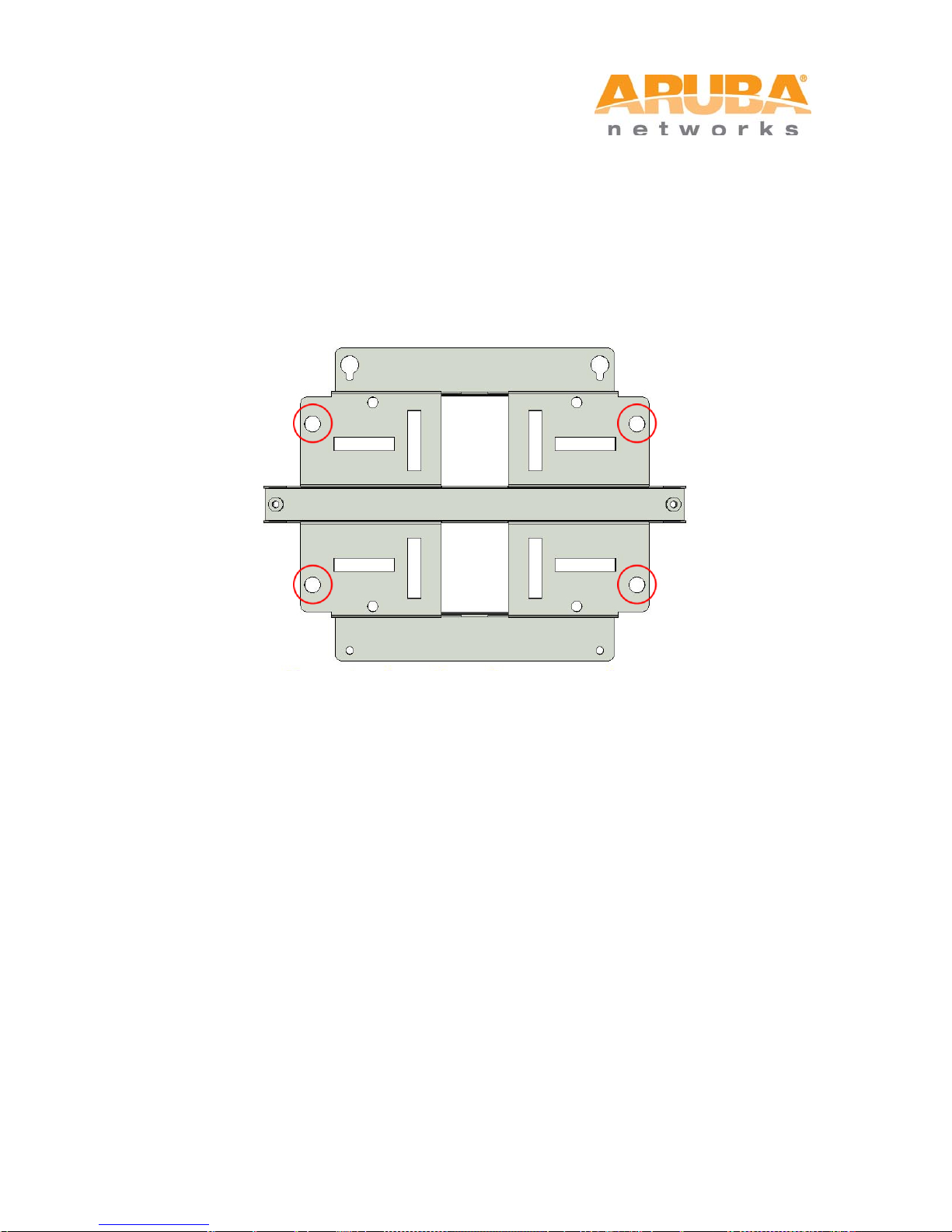
4.2 Installing the MSR4000 on a Wall
Step 1 Mark the screw points.
1) Put the mounting bracket on the installation posit ion against the wall.
2) Mark four expansion screw holes on the wall.
Figure 4-8 Position of Screw Holes
Step 2 Drill holes
1) Use a percussion drill to drill four holes on t he four markings. (Expansion screw size: M8 x
100mm)
Step 3 Install masonry anchors
1) Insert a masonry anchor into each drilled hole vertic al ly.
2) Tap the flat end of the anchor with a rubber hammer until the anchor is flush with the wall
surface.
Step 4 Fix the wall-mounting bracket
1) Align the four holes in the wall-mounting bracket wi th the anchors and insert four
expansion screws through the installat ion holes into the anchors.
2) Adjust the position of the wall-mounting bracket and tighten the expansion screws.
Step 5 Hang the MSR4000 on the bracket
1) Screw the two M4 x16 bolts into the holes on the back of the MSR4000.
2) Align the two M4 x16 bolts on the back of MSR4000 with the holes on the mounting
bracket and hang the MSR4000 on the bracket.
MSR4000 Installation Guide 29

1
Hang the two M4 x16 bolts of the back of the MSR4000 on the two
Figure 4-9 Positions of the Two M4 x16 Bolts and the Holes
holes of the mounting bracket.
Step 6 Fix the MSR4000
1) Align the two installation holes in the MSR4000 with the corresponding holes in the wall-
mounting bracket.
2) Insert the two M6 x30 bolts (with flat and spring washers) through the installation holes,
and tighten the bolts.
Figure 4-10 Positions of installation Holes
Left side Right side
30 MSR4000 Installation Guide

4.3 Grounding the MSR4000
The grounding must be completed before powering up the MSR4000.The residence of
grounding wire should be less than 5 ohm and the groundi ng cable’s cross-section area
2
should be no less than 6 mm
.The grounding hole is at the left side of the MSR4000.
Figure 4-11 Grounding the MSR4000
Step 1 Peel the cover of one end of the grounding cable (green or yellow and green
grounding cable) and place the bare grounding cable into the copper lug, and press
firmly with the crimping pliers.
Step 2 Fasten the copper lug to the grounding hole on the MSR4000 with the M4 x12 bolt
and external-tooth washer.
MSR4000 Installation Guide 31

Grounding cable for lightning
4.4 Connecting the RF Cable
The RF cable is used to connect the antennas and the MSR4000.
Note
You must install the lightning arrester between the antenna and the MSR4000.
Figure 4-12 Connecting the RF Cable
1 RF cable 3
2 Lightning arrester 4 Antenna interface
Step 1 Screw one end of the lightning arrester onto t he antenna interface.
Step 2 Connect the RF cable to the other end of the lightning arrester.
Step 3 Water-proof
tape and strap.
Note
One directional dual-polarization antenna needs two RF cables to connect to two
corresponding antenna interfaces on MSR4000. For example, if the antenna needs to
connect to Radio 0 on MSR4000, the RF cables from antenna needs to connect to Antenna
1 (Radio 0) interface and Antenna 2 (Radio 0) interf ace in Figure 4-13.
the antenna connection with PVC insulat i on tape, adhesive insulation
arrester
32 MSR4000 Installation Guide

Figure 4-13 Antenna Interfaces on MSR4000 (MSR4KAC shown)
MSR4000 Installation Guide 33

1
Shielded RJ45 connector
5
Shield rings
2
Waterproof connector socket
6
Sealing bolt
3
Locknut
7
Sealing nut
4
Clamp ring
4.5 Connecting the Ethernet Cable
To ensure that MSR4000 maintains Ethernet connectivity and Power over Ethernet (PoE),
you must use the weatherproof connector kit and install it using the steps below.
Note
Failure to use the weatherproof connector kit can lead to connectivity and PoE issues.
Figure 4-14 Weatherproof Connector Kit
1. Hold the clamp ring (4) vertic ally, with the wide end facing up, and pl ace the locknut (3)
over it.
2. Drop the waterproof connector sock et (2) into the locknut/clamp ring items (3, 4), wit h
the RJ45 connector opening facing up, and screw the socket into the threads on the
clamp ring.
3. Place the sealing nut (7) over an Ethernet cable (without a connector attached to the
end).
34 MSR4000 Installation Guide

4. Place the seal bolt (6) over the Ethernet cable.
5. Strip off about 55mm (2 inches) of the outer Et hernet c able sheath t o expose the ground
wire and other pair wires.
6. Insert all pair wires into the two shield rings (5).
7. Make the ground wire attach to the narrow end of the inner ring and pl ace the outer ring
over the narrow end of the inner ring.
8. Insert the Ethernet cable i nto the narrow end of the clamp ring and pass it through the
opening end of waterproof connector socket.
9. Using a crimping tool, attach t he included shielded RJ45 connector.
10. Slide the shield rings up the E thernet c able and i n sert it into t he narrow e nd of the clamp
ring.
11. Pull the Ethernet cable so the shielded RJ45 connector fits into the RJ45 shaped
opening in the wide end of the weatherproof connector socket.
Note
For outdoor use, the RJ45 must be installed with a waterpro ofing gasket.
12. Slide the sealing bolt over the narrow end of the clamp ring and hand tighten it.
13. Thread the sealing nut onto the sealing bolt.
14. Insert the Ethernet cable connector into the Ethernet interface and hand-tighten the
locknut.
15. Water-proof the Ethernet cable connecti on wi th PVC insulation tape and adhesive tape.
Figure 4-15 Connecting Ethernet Cable to the Ethernet interface
MSR4000 Installation Guide 35

Part number
Description
CBL-AC-NA
Weatherproof AC power cable (5m), North America version
CBL-AC-INTL
Weatherproof AC power cable (5m), International (EU) version
CKIT-AC-M
Weatherproof connector kit for AC power interface
Note
• The Ethernet c abl e and power cable need proper drip loops. Drip loops prevent
water from entering the router through the connectors.
• It is recommended to fix the Ethernet cable near the MSR2000 side to the wall or the
pole. This is to ensure that the weight of the cable does not affect the RJ45 connector.
4.6 Connecting the Power Cable (MSR4KAC)
The MSR4KAC version needs an outdoor rated power cable to connect to a compatible AC
power source.
Note
The MSR4000 does not ship with any power cables; these are available as accessories
and should be ordered separately.
• AC power source spec i fications (at MSR4000 interface): 100-240Vac, 100W
4.6.1 Powering the MSR4KAC
The MSR2KAC comes with two power cord variants and a kit is also offered to allow
customers to assemble their own cables if the s tandard offerings do not meet deployment
needs.
The following table summarizes the powering accessories available for the MSR2KAC:
Table 4-1 SKUs for Powering Options
The difference between the NA and INTL AC cable part is the color coding of the conductors.
.
• The North American cable uses Black (Hot), White (Neutral), and Green (Ground).
• The INTL part follows the international schema of Brown (Hot), Blue (Neutral) and
Yellow/Green (Ground)
36 MSR4000 Installation Guide

4.6.2 Best practices for Outdoor Connection to AC Mains
• With virtually all infrastructure equipment that is i nstalled outdoors connection to AC
mains should be accomplished with an outdoor rat ed ju nction box.
Note
The connection to the AC mains must be implemented by a qualified resource in a
manner that is consistent with the electric al code in force in the jurisdiction of
deployment. In many countries a licensed elect rician must perform this operation. In
Japan, this would require an electrician cert ified by the Ministry of Economy, Trade, and
Industry.
• In the event that a plug i s wired onto the cable assembly, the electric ian must follow
4.6.3 Using the CKIT-AC-M
The assembly instructions for the CKIT-AC-M are shipped along wit h the part. All instructions
must be followed to ensure proper assembly of the connector onto the cable.
The specifications for third-party cables used with the CKIT are as follows:
• AC power cable speci fications (when using CKIT-AC-M connector k i t and custom
4.6.4 AC Power Connector PIN OUT on the MSR4KAC
all instructions provided while attaching a plug to the cable assemblies. The
connections must be consistent with the local el ectrical code. The use of plugs with
infrastructure equipments is suitable onl y f or temporary installations where the
nuisance tripping of the GFI plugs is considered t olerable.
cable): minimum voltage/current rating 250V/1A, diameter 6-12mm, rated for outdoor
use and UV exposure.
Figure 4-16 Power Interface on the MSR4KAC and the AC Power Cable Connector
Power Interface on MSR4KAC AC Power Cable Connector
MSR4000 Installation Guide 37

4.6.5 Connecting the Power Cable to the MSR4KAC
Step 1 Remove the protective cap on the power interface.
Step 2 Insert the power cable connector into the power interface and hand-fasten the
waterproof cover.
Step 3 Water-proof
insulation tape and strap.
Figure 4-17 Connecting the Power Cable to the Power Interface
the power cable connection with PVC insulation tape, adhesive
38 MSR4000 Installation Guide

5 Note
Browser
Microsoft Internet Explorer, Mozilla Firefox, or any
other standard browser.
Default IP address
http://192.168.216.1
SSID
ArubaDefault
802.11 mode
802.11ng
Channel
1
Country/Region Code
US
Authentication/Encryption
None
DHCP
Disabled
Product SKUs
Serial Number
Baud
Data
Parity
Stop
Flow
To log in to the MSR4000 via the WMI (Web Management Interface), use the settings as
shown in the table below:
For additional details, refer to the Aruba MeshOS User Guide.
To log in to the MSR4000 via the console port, use the settings as sh own in the table
below:
The default username is root and the password is public.
Rate
MSR4K43N0, MSR4K43N0-JP,
MSR4K43N0-US
MSR4K43N3, MSR4K43N3-JP,
MSR4K43N3-US
MSR4KP, MSR4KP-JP,
MSR4KP-US, MSR4KP-IL
MSR4KAC, MSR4KAC-JP,
MSR4KAC-US, MSR4KAC-IL
The baudrate setting depends on the manufacturing date of the MSR4000 (before or after
March 2012) and the Serial Number (14 characters or 9 charac ters). The table lists all the
14 characters
(For example:
26A02110500467)
9 characters
(For example:
AZ1234567)
115200 8 None 1 None
9600 8 None 1 None
Bits
Bits
Control
SKUs for this product along with the corresponding baudrate.
MSR4000 Installation Guide 39

6 Product Specifications
Mechanical
Dimensions(H x W x D)
13 inches x 11.5 inches x 5 inches
325 mm x 290 mm x 135 mm
Weight
MSR4KP: 12.1 lbs/5.5 kg
MSR4KAC: 14.3 lbs/6.5 kg
Shipping Dimensions(H x W x D)
16.3 inches x 13.9 inches x 16.9 inches
415 mm x 352 mm x 428 mm
Shipping Weight
MSR4KP: 25.9 lbs/11.75kg
MSR4KAC: 28.1 lbs/12.75 kg
Temperature
Operating(MSR4KP): -30ºC to 60ºC (-22ºF to 140ºF)
Operating(MSR4KAC): -40ºC to 55ºC (-40ºF to 131ºF)
Storage: -30ºC to 70º C (-22ºF to 158ºF)
Mounting: wall or pole mountable
Antennas:
Eight N-type (female) interfaces for external antenna support
Feeder cable may be used for external antenna deployments
Visual Status Indicators (LEDs): See Table 1-1 and Table 1-2
Electrical
Power:
MSR4KP: High power PoE (60 watts) input required
MSR4KAC: 100-240 VAC 50/60 Hz
Power Consumption: 36 watts max (excludes power consumed by any PoE devi ce
connected to and powered by the MSR4KAC)
40 MSR4000 Installation Guide

Interfaces
Network:
1 x 10/100/1000BASE-T Ethernet (RJ-45)
Power:
1 X AC power connector (in MSR4KAC model only)
Antenna
8 x N-type antenna interf aces
Other:
1 x USB console interface
Wireless LAN
AP type: outdoor, four radio, dual band plus 4.9-GHz public safety band
Supported frequenc y bands (country-specific restrictions appl y)
2.400 to 2.483 GHz
4.900 to 5.100 GHz
5.150 to 5.250 GHz
5.250 to 5.350 GHz
5.470 to 5.725 GHz
5.725 to 5.850 GHz
Available channels: Dependent upon configured regulatory dom ai n
Supported radio technologies:
802.11b: Direct -s equence spread-spectrum (DSSS)
802.11a/g/n: Orthogonal frequency division multiplexing (OFDM)
802.11n: 2x2 MIMO wi th two spatial streams
Supported modulation types:
802.11b: BPSK, QPSK, CCK
802.11a/g/n: BPSK, QPSK, 16-QAM, 64-QAM
Maximum transmit power: 25 dBm (325 mW) limited by local regulatory requirement s
Association rates (Mbps):
802.11b: 1, 2, 5.5, 11
802.11a/g: 6, 9, 12, 18, 24, 36, 48, 54
802.11n: MCS0 - MCS15 (6.5 Mbps to 300 Mbps)
802.11n high-throug hput (HT) support: HT 20/40
802.11n packet aggregation: A-MPDU, A-MSDU
MSR4000 Installation Guide 41

7 Contacting Support
Main Site arubanetworks.com
Support Site support.arubanetworks.com
Airheads Social Forums and
Knowledge Base
North American Telephone 1-800-943-4526 (Toll Free)
International Telephones
Software Licensing Site licensing.arubanetworks.com/login.php
Wireless Security Incident
Response Team (WSIRT)
Support Email Addresses
Americas and APAC support@arubanetworks.com
community.arubanetworks.com
1-408-754-1200
arubanetworks.com/support-services/aruba-supportprogram/contact-support/
arubanetworks.com/support/wsirt.php
EMEA emea_support@arubanetworks.com
WSIRT Email
Please email details of any
security problem found in an
Aruba product.
42 MSR4000 Installation Guide
wsirt@arubanetworks.com
 Loading...